

CL-60E CL-60A
Conext™ CL-60 PV Inverter
Owner’s Guide
975-0768-01-01 Revision B
03-2017
http://solar.schneider-electric.com


Conext™ CL-60 PV Inverter
Owner’s Guide
http://solar.schneider-electric.com

Copyright © 2017 Schneider Electric. All Rights Reserved. All trademarks are owned by Schneider Electric Industries SAS
or its affiliated companies. Other 3rd party trademarks are owned by their respective companies.
Exclusion for Documentation
U
NLESS SPECIFICALLY AGREED TO IN WRITING, SELLER
(A) MAKES NO WARRANTY AS TO THE ACCURACY, SUFFICIENCY OR SUITABILITY OF ANY TECHNICAL OR OTHER INFORMATION PROVIDED
IN ITS MANUALS OR OTHER DOCUMENTATION;
(
B) ASSUMES NO RESPONSIBILITY OR LIABILITY FOR LOSSES, DAMAGES, COSTS OR EXPENSES, WHETHER SPECIAL, DIRECT, INDIRECT,
CONSEQUENTIAL OR INCIDENTAL, WHICH MIGHT ARISE OUT OF THE USE OF SUCH INFORMATION. THE USE OF ANY SUCH INFORMATION
WILL BE ENTIRELY AT THE USER’S RISK; AND
(C) REMINDS YOU THAT IF THIS MANUAL IS IN ANY LANGUAGE OTHER THAN ENGLISH, ALTHOUGH STEPS HAVE BEEN TAKEN TO
MAINTAIN THE ACCURACY OF THE TRANSLATION, THE ACCURACY CANNOT BE GUARANTEED. APPROVED CONTENT IS CONTAINED WITH
THE ENGLISH LANGUAGE VERSION WHICH IS POSTED AT SOLAR.SCHNEIDER-ELECTRIC.COM.
Document Number: 975-0768-01-01 Revision: Revision B Date: 03-2017
Product Part Numbers: PVSCL60A (CL-60A—North American version)
PVSCL60E (CL-60E—IEC version)
Contact Information: http://solar.schneider-electric.com
Please contact your local Schneider Electric Sales Representative or visit our website at:
http://solar.schneider-electric.com/tech-support/

About This Guide
Purpose
The purpose of this Owner’s Guide is to explain the procedures for operating,
configuring, maintaining, and troubleshooting the Conext CL-60 PV Inverter.
Scope
The Guide provides safety guidelines and general information for installing and
operating the Conext CL-60, as well as information about configuring,
monitoring, and troubleshooting the unit. It does not include information on how
to use other Schneider Electric and third-party products.
Audience
The Guide is intended for use by anyone who plans to design, construct, install,
or operate a system involving the CL-60. The installation information in this guide
is intended for qualified personnel. Qualified personnel have training,
knowledge, and experience in:
• Installing electrical equipment and PV power systems (up to 1000 volts)
• Applying all applicable installation codes
• Analyzing and reducing the hazards involved in performing electrical work
• Selecting and using Personal Protective Equipment (PPE)
975-0768-01-01 Revision B v
About This Guide
Organization
This Guide is organized into:
Chapter 1, “Introduction”
Chapter 2, “Installation”
Chapter 3, “Electrical Connections”
Chapter 4, “Commissioning”
Chapter 5, “LCD Display Operation”
Chapter 6, “Troubleshooting”
Chapter 7, “Disconnecting, Dismantling, and Disposing the CL-60”
Chapter 8, “Specifications”
Abbreviations and Acronyms
Related Information
AFD
EMI
G
GND
HMI
IGBT
LAN / WAN
LCD
LED
NFPA
PE
PPE
PV
SPD
You can find more information about Schneider Electric, as well as its products
and services at http://solar.schneider-electric.com.
Arc Fault Detection device
Electromagnetic Interference
Ground (also referred as Protective Earth)
Human-Machine Interface
Insulated Gate Bipolar Transistor
Local Area Network / Wide Area Network
Liquid Crystal Display (used for HMI displays)
Light Emitting Diode (used for indicator lights)
National Fire Protection Association
Protective Earth (also referred as Ground)
Personal Protective Equipment
Photovoltaic (or Solar)
Surge Protection Device
vi 975-0768-01-01 Revision B
Important Safety Instructions
DANGER
WARNING
CAUTION
NOTICE
READ AND SAVE THESE INSTRUCTIONS - DO NOT DISCARD
This document contains important safety instructions that must be followed
during installation procedures (if applicable). Read and keep this Owner’s Guide
for future reference.
Read these instructions carefully and look at the equipment (if applicable) to
become familiar with the device before trying to install, operate, service or
maintain it. The following special messages may appear throughout this bulletin
or on the equipment to warn of potential hazards or to call attention to information
that clarifies or simplifies a procedure.
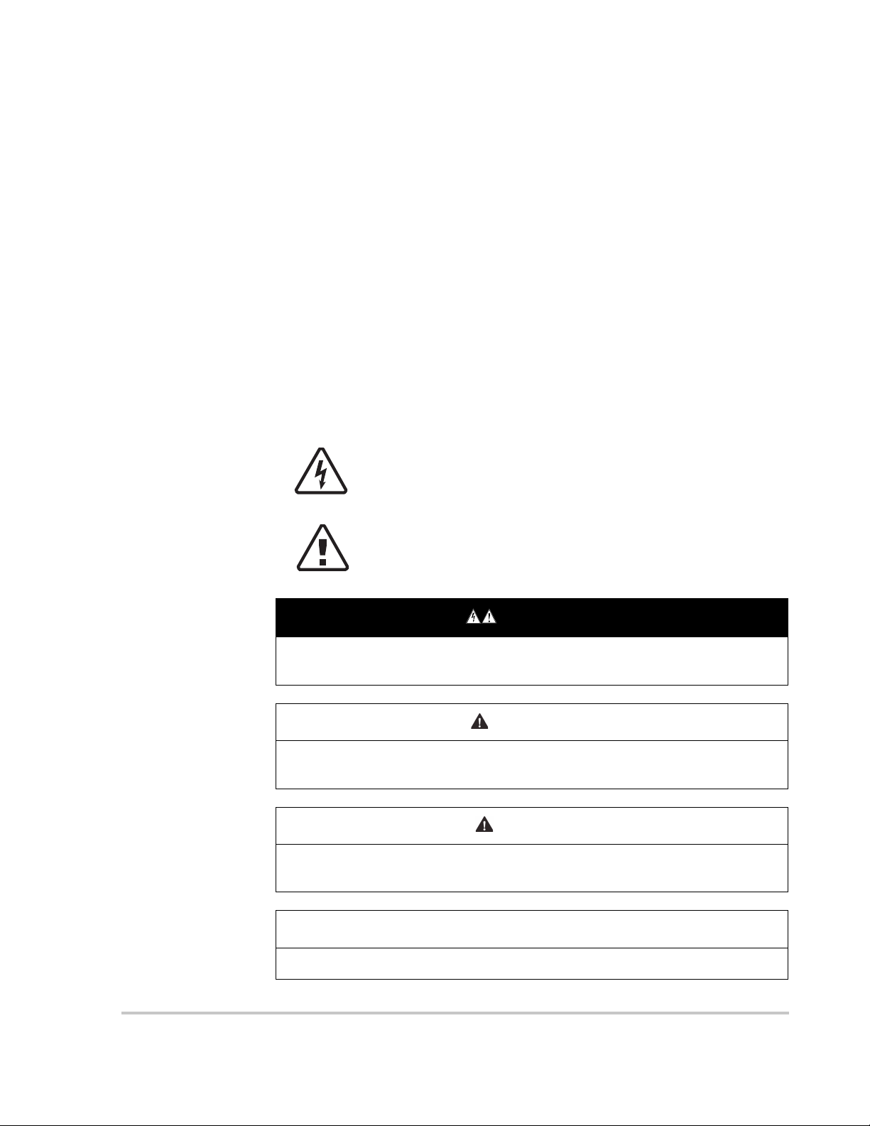
The addition of either symbol to a “Danger” or “Warning” safety
label indicates that an electrical hazard exists which will result
in personal injury if the instructions are not followed.
This is the safety alert symbol. It is used to alert you to potential
personal injury hazards. Obey all safety messages that follow
this symbol to avoid possible injury or death.
DANGER indicates an imminently hazardous situation, which, if not avoided,
will result in death or serious injury.
WARNING indicates a potentially hazardous situation, which, if not avoided,
can result in death or serious injury.
CAUTION indicates a potentially hazardous situation, which, if not avoided,
can result in moderate or minor injury.
NOTICE indicates important information that you need to read carefully.
975-0768-01-01 Revision B vii

Safety
Please Note
Electrical equipment must be installed, operated, serviced, and maintained only
by qualified personnel. No responsibility is assumed by Schneider Electric for
any consequences arising out of the use of this material.
A qualified person is one who has skills and knowledge related to the
construction, installation, and operation of electrical equipment and has received
safety training to recognize and avoid the hazards involved.
Safety Information
1. Before using this product, read all instructions and cautionary markings on
the unit and all appropriate sections of this manual.
2. Use of accessories not recommended or sold by the manufacturer may result
in a risk of fire, electric shock, or injury to persons.
3. The manufacturer recommends that all wiring be done by a certified
technician or electrician to ensure adherence to the local and national
electrical codes applicable in your jurisdiction.
4. To avoid a risk of fire and electric shock, make sure that existing wiring is in
good condition and that wire is not undersized. Do not operate the
equipment with damaged or substandard wiring.
5. Do not operate the equipment if it has been damaged in any way.
6. Do not disassemble the Conext CL-60 except where noted for connecting
wiring and cabling. See your warranty for instructions on obtaining service.
Attempting to service the unit yourself may result in a risk of electrical shock
or fire.
7. To reduce the risk of electrical shock, disconnect the power supply from the
equipment before attempting installation, and any maintenance (including
cleaning or working on any components connected to the equipment).
Internal capacitors remain charged for ten minutes after all power is
disconnected.
8. The equipment must be grounded. Use the protective grounding conductor
provided with the AC input conductors.
9. This product is designed for outdoor use and is rated IP65 and Type 4X.
10. To reduce the chance of short-circuits, always use insulated tools when
installing or working with this equipment. Do not leave tools inside.
11. Remove personal metal items such as rings, bracelets, necklaces, and
watches when working with electrical equipment.
12. Do not open nor disassemble the top half of the unit. There are no userserviceable parts inside.
13. To disconnect the unit from DC power, turn the DC switch to OFF and then
remove all PV string connectors from the DC terminals.
viii 975-0768-01-01 Revision B
Safety
DANGER
NOTICE
ELECTRIC SHOCK, EXPLOSION, OR ARC FLASH HAZARDS
• Apply appropriate personal protective equipment (PPE) and follow safe
electrical work practices.
• This equipment must only be installed and serviced by qualified electrical
personnel.
• Never energize the inverter with the covers removed.
• Do not open fuse holders under load. The fuse must be de-energized from
all sources before servicing.
• The inverter is energized from multiple sources. Before removing covers
identify all source, de-energize, lock-out, and tag-out and wait 10 minutes.
• Always use a properly rated voltage sensing device to confirm all circuits
are de-energized.
• Replace all devices and covers before turning on power to this equipment.
• The DC conductors of this photovoltaic system are ungrounded and may
be energized.
Failure to follow these instructions will result in death or serious injury.
Access to live parts shall be limited to suitably qualified electrical personnel. See
installation instructions before connecting to the supply.
EQUIPMENT DAMAGE
• All cables connected to the CL-60 must run through the cable glands on
the unit.
• This unit is susceptible to damage from EMI and nearby lightning strikes
unless a surge protection device (a lightning arrestor) is installed.
• Turn Off all devices before connecting cables.
• Use the CL-60’s DC switch as its On/Off switch.
• To isolate the CL-60, follow “Lock-Out Tag-Out (LOTO) Procedure” on
page xi.
Failure to follow these instructions can damage equipment or affect
network performance.
975-0768-01-01 Revision B ix

Safety
Storage Information
Store the inverter properly when the inverter is not to be installed immediately.
1. Inverter must be packed inside its original carton with the desiccant bags
inside.
2. Store the inverter with its front panel facing up. The carton should lay flat and
parallel to the ground.
3. Seal the carton with standard packaging tape.
4. Store the inverter in a dry and clean place to protect it against dust and
moisture.
5. Temperature: -30 to 85 °C (-22 to 185 ºF)
Relative humidity: 0 to 100%.
6. Do not stack more than two inverters on top of another.
7. Keep the inverter away from chemically corrosive materials.
8. Periodically check for any visible damages to the carton and inspect the
inverter right away if the carton shows signs of penetration during the storage
period. Replace the carton, if necessary.
NOTE: A thorough and professional inspection may be required before
installing the inverter after more than six months in storage. Contact a local
Schneider Electric sales representative for information on how to arrange the
inspection.
IMPORTANT: Storage beyond two years voids the warranty.
x 975-0768-01-01 Revision B
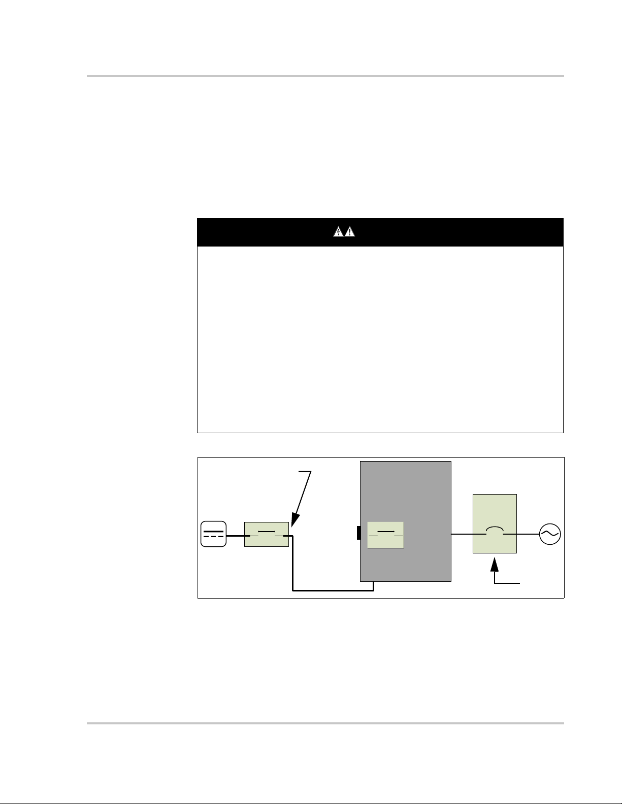
Lock-Out Tag-Out (LOTO) Procedure
DANGER
CL-60
Mains
AC Panel
Breaker
DC Disconnect Device
LOTO
LOTO
DC Switch
PV string
Lock-out refers to the practice of preventing de-energized circuits from being reenergized by putting locks on the disconnecting devices, holding them open.
Tag-out refers to the practice of attaching a tag to the disconnect-device locks
warning others not to operate the disconnect device and containing information
relating to the lock-out, such as the person responsible, the reason, and the date
and time. Combined these two practices are called the lock-out and tag-out
(LOTO) procedure.
ELECTRIC SHOCK, EXPLOSION, OR ARC FLASH HAZARDS
• Apply appropriate personal protective equipment (PPE) and follow safe
electrical work practices.
• This equipment must only be installed and serviced by qualified electrical
personnel.
• Never energize the inverter with the covers removed.
• Always use a properly rated voltage sensing device to confirm all circuits
are de-energized.
• Replace all devices and covers before turning on power to this equipment.
• The inverter is energized from multiple sources. Before opening the cover
identify the power source (see A), de-energize (see B), lock-out and tagout (see C), and wait ten minutes for circuits to discharge (see D).
Failure to follow these instructions will result in death or serious injury.
Safety
Figure 1-1 Single Line Diagram for CL-60
A 1. Identify any disconnect device upstream from the CL-60 unit.
B 2. Open the disconnect device that connects to the CL-60 to cut off DC power.
C 3. Turn the CL-60’s DC Switch to OFF position.
4. Lock-out and tag out the external DC disconnect device.
5. Remove all PV string connectors from the DC terminals.
975-0768-01-01 Revision B xi

Safety
A 6. Identify the AC Panel Breaker downstream from the CL-60 unit.
B 7. Open the AC Panel door.
8. Turn Off the AC Panel Breaker (open the switch) that connects to the CL-60
to cut off AC power.
9. Close the AC Panel door.
C 10. Lock-out and tag out the AC Panel.
D 11. Wait ten minutes for the circuits in the CL-60 to discharge.
12. Check that the inverter is in zero energy state before performing work.
13. Open the CL-60 enclosure and commence service and maintenance
activities.
xii 975-0768-01-01 Revision B

Contents
Important Safety Instructions
Safety Information - - - - - - - - - - - - - - - - - - - - - - - - - - - - - - - - - - - - - - - - - - - - - - - - - - - - - - - - - viii
Storage Information - - - - - - - - - - - - - - - - - - - - - - - - - - - - - - - - - - - - - - - - - - - - - - - - - - - - - - - - - x
Lock-Out Tag-Out (LOTO) Procedure - - - - - - - - - - - - - - - - - - - - - - - - - - - - - - - - - - - - - - - - - - - -xi
1 Introduction
Conext CL-60 - - - - - - - - - - - - - - - - - - - - - - - - - - - - - - - - - - - - - - - - - - - - - - - - - - - - - - - - - - - - 1–2
Physical Features - - - - - - - - - - - - - - - - - - - - - - - - - - - - - - - - - - - - - - - - - - - - - - - - - - - - - - - - - 1–4
Dimensions - - - - - - - - - - - - - - - - - - - - - - - - - - - - - - - - - - - - - - - - - - - - - - - - - - - - - - - - - - 1–5
Inverter Dimensions - - - - - - - - - - - - - - - - - - - - - - - - - - - - - - - - - - - - - - - - - - - - - - - - - 1–5
Packaging Box Dimensions - - - - - - - - - - - - - - - - - - - - - - - - - - - - - - - - - - - - - - - - - - - - 1–5
Product Label - - - - - - - - - - - - - - - - - - - - - - - - - - - - - - - - - - - - - - - - - - - - - - - - - - - - - - 1–6
LCD Display - - - - - - - - - - - - - - - - - - - - - - - - - - - - - - - - - - - - - - - - - - - - - - - - - - - - - - - - - - 1–7
DC Switch - - - - - - - - - - - - - - - - - - - - - - - - - - - - - - - - - - - - - - - - - - - - - - - - - - - - - - - - - - - 1–8
Technical Features - - - - - - - - - - - - - - - - - - - - - - - - - - - - - - - - - - - - - - - - - - - - - - - - - - - - - - - - 1–9
CL-60 Circuit Diagram - - - - - - - - - - - - - - - - - - - - - - - - - - - - - - - - - - - - - - - - - - - - - - - - - - - 1–9
Standard Features - - - - - - - - - - - - - - - - - - - - - - - - - - - - - - - - - - - - - - - - - - - - - - - - - - - - - 1–9
Derating Feature - - - - - - - - - - - - - - - - - - - - - - - - - - - - - - - - - - - - - - - - - - - - - - - - - - - - - - 1–10
2 Installation
Pre-Installation - - - - - - - - - - - - - - - - - - - - - - - - - - - - - - - - - - - - - - - - - - - - - - - - - - - - - - - - - - - 2–2
Planning the Installation - - - - - - - - - - - - - - - - - - - - - - - - - - - - - - - - - - - - - - - - - - - - - - - - - - 2–2
Installation - - - - - - - - - - - - - - - - - - - - - - - - - - - - - - - - - - - - - - - - - - - - - - - - - - - - - - - - - - - - - - 2–3
What’s In The Box - - - - - - - - - - - - - - - - - - - - - - - - - - - - - - - - - - - - - - - - - - - - - - - - - - - - - - 2–3
Material and Tools - - - - - - - - - - - - - - - - - - - - - - - - - - - - - - - - - - - - - - - - - - - - - - - - - - - - - - 2–4
Location Information - - - - - - - - - - - - - - - - - - - - - - - - - - - - - - - - - - - - - - - - - - - - - - - - - - - - 2–4
Install and Mount the CL-60 - - - - - - - - - - - - - - - - - - - - - - - - - - - - - - - - - - - - - - - - - - - - - - - 2–8
Torque Values - - - - - - - - - - - - - - - - - - - - - - - - - - - - - - - - - - - - - - - - - - - - - - - - - - - - - - - 2–15
3 Electrical Connections
Precautions - - - - - - - - - - - - - - - - - - - - - - - - - - - - - - - - - - - - - - - - - - - - - - - - - - - - - - - - - - - - - 3–2
Planning the Electrical Connections - - - - - - - - - - - - - - - - - - - - - - - - - - - - - - - - - - - - - - - - - 3–2
Cabling and Wiring - - - - - - - - - - - - - - - - - - - - - - - - - - - - - - - - - - - - - - - - - - - - - - - - - - - - - - - - 3–3
Material and Tools - - - - - - - - - - - - - - - - - - - - - - - - - - - - - - - - - - - - - - - - - - - - - - - - - - - - - - 3–3
Terminal and Cable Entry Points (for CL-60E) - - - - - - - - - - - - - - - - - - - - - - - - - - - - - - - - - - 3–5
Terminal and Cable Entry Points (for CL-60A) - - - - - - - - - - - - - - - - - - - - - - - - - - - - - - - - - - 3–6
AC Side Cable Connection - - - - - - - - - - - - - - - - - - - - - - - - - - - - - - - - - - - - - - - - - - - - - - - 3–7
AC Side Requirements - - - - - - - - - - - - - - - - - - - - - - - - - - - - - - - - - - - - - - - - - - - - - - - 3–7
AC Circuit Breaker - - - - - - - - - - - - - - - - - - - - - - - - - - - - - - - - - - - - - - - - - - - - - - - - - - 3–7
Residual Current Device - - - - - - - - - - - - - - - - - - - - - - - - - - - - - - - - - - - - - - - - - - - - - - 3–7
975-0768-01-01 Revision B xiii

Contents
Multiple Inverters in Parallel Connection - - - - - - - - - - - - - - - - - - - - - - - - - - - - - - - - - - - 3–8
Grid Connection - - - - - - - - - - - - - - - - - - - - - - - - - - - - - - - - - - - - - - - - - - - - - - - - - - - - 3–9
PV Array Connection - - - - - - - - - - - - - - - - - - - - - - - - - - - - - - - - - - - - - - - - - - - - - - - - - - - 3–14
PV Input Configuration - - - - - - - - - - - - - - - - - - - - - - - - - - - - - - - - - - - - - - - - - - - - - - 3–14
PV Input Connection - - - - - - - - - - - - - - - - - - - - - - - - - - - - - - - - - - - - - - - - - - - - - - - - 3–16
Grounding the Inverter - - - - - - - - - - - - - - - - - - - - - - - - - - - - - - - - - - - - - - - - - - - - - - - - - 3–21
Grounding System Overview - - - - - - - - - - - - - - - - - - - - - - - - - - - - - - - - - - - - - - - - - - 3–21
Second Protective Earth Terminal - - - - - - - - - - - - - - - - - - - - - - - - - - - - - - - - - - - - - - 3–22
Communication Connection - - - - - - - - - - - - - - - - - - - - - - - - - - - - - - - - - - - - - - - - - - - - - - - - 3–23
Overview - - - - - - - - - - - - - - - - - - - - - - - - - - - - - - - - - - - - - - - - - - - - - - - - - - - - - - - - - - - 3–23
RS-485 Communication System - - - - - - - - - - - - - - - - - - - - - - - - - - - - - - - - - - - - - - - - - - - 3–24
Ethernet Connection - - - - - - - - - - - - - - - - - - - - - - - - - - - - - - - - - - - - - - - - - - - - - - - - - - - 3–28
4 Commissioning
Inspection Before Commissioning - - - - - - - - - - - - - - - - - - - - - - - - - - - - - - - - - - - - - - - - - - - - - 4–2
Commissioning Procedure - - - - - - - - - - - - - - - - - - - - - - - - - - - - - - - - - - - - - - - - - - - - - - - - - - 4–2
5 LCD Display Operation
Description of the Selection Buttons - - - - - - - - - - - - - - - - - - - - - - - - - - - - - - - - - - - - - - - - - - - 5–2
Menu Tree - - - - - - - - - - - - - - - - - - - - - - - - - - - - - - - - - - - - - - - - - - - - - - - - - - - - - - - - - - - - - - 5–3
Main Screen - - - - - - - - - - - - - - - - - - - - - - - - - - - - - - - - - - - - - - - - - - - - - - - - - - - - - - - - - - - - 5–4
Contrast Adjustment - - - - - - - - - - - - - - - - - - - - - - - - - - - - - - - - - - - - - - - - - - - - - - - - - - - - - - - 5–6
Checking Running Information - - - - - - - - - - - - - - - - - - - - - - - - - - - - - - - - - - - - - - - - - - - - - - - 5–6
Checking History Information - - - - - - - - - - - - - - - - - - - - - - - - - - - - - - - - - - - - - - - - - - - - - - - - 5–8
Checking Running Records - - - - - - - - - - - - - - - - - - - - - - - - - - - - - - - - - - - - - - - - - - - - - - - 5–8
Checking Fault (Event) Records - - - - - - - - - - - - - - - - - - - - - - - - - - - - - - - - - - - - - - - - - - - 5–8
Checking History Event Records - - - - - - - - - - - - - - - - - - - - - - - - - - - - - - - - - - - - - - - - - - - 5–9
Checking Energy Records - - - - - - - - - - - - - - - - - - - - - - - - - - - - - - - - - - - - - - - - - - - - - - - 5–9
Starting/Stopping - - - - - - - - - - - - - - - - - - - - - - - - - - - - - - - - - - - - - - - - - - - - - - - - - - - - - - - - 5–10
Password Entry - - - - - - - - - - - - - - - - - - - - - - - - - - - - - - - - - - - - - - - - - - - - - - - - - - - - - - - - - 5–11
System Parameter Setting - - - - - - - - - - - - - - - - - - - - - - - - - - - - - - - - - - - - - - - - - - - - - - - - - - 5–12
Language Setting - - - - - - - - - - - - - - - - - - - - - - - - - - - - - - - - - - - - - - - - - - - - - - - - - - - - - 5–12
Time Setting - - - - - - - - - - - - - - - - - - - - - - - - - - - - - - - - - - - - - - - - - - - - - - - - - - - - - - - - - 5–12
Total Energy Deviation Adjustment - - - - - - - - - - - - - - - - - - - - - - - - - - - - - - - - - - - - - - - - - 5–13
Load Default (Factory Reset) - - - - - - - - - - - - - - - - - - - - - - - - - - - - - - - - - - - - - - - - - - - - - 5–14
Checking Firmware Version - - - - - - - - - - - - - - - - - - - - - - - - - - - - - - - - - - - - - - - - - - - - - - 5–14
Running Parameter Setting - - - - - - - - - - - - - - - - - - - - - - - - - - - - - - - - - - - - - - - - - - - - - - - - - 5–15
Main Screen of Run-param - - - - - - - - - - - - - - - - - - - - - - - - - - - - - - - - - - - - - - - - - - - - - - 5–15
Active/Reactive Power Parameters - - - - - - - - - - - - - - - - - - - - - - - - - - - - - - - - - - - - - - - - - 5–18
Reactive Power Regulation - - - - - - - - - - - - - - - - - - - - - - - - - - - - - - - - - - - - - - - - - - - - - - 5–18
Pf Mode - - - - - - - - - - - - - - - - - - - - - - - - - - - - - - - - - - - - - - - - - - - - - - - - - - - - - - - - - 5–18
Qt Mode - - - - - - - - - - - - - - - - - - - - - - - - - - - - - - - - - - - - - - - - - - - - - - - - - - - - - - - - 5–19
Off Mode - - - - - - - - - - - - - - - - - - - - - - - - - - - - - - - - - - - - - - - - - - - - - - - - - - - - - - - - 5–19
Q(P) Mode (when the country selection is not “IT”) - - - - - - - - - - - - - - - - - - - - - - - - - - 5–19
xiv 975-0768-01-01 Revision B

Q(U) Mode (when the country selection is not “IT”) - - - - - - - - - - - - - - - - - - - - - - - - - - 5–20
Reactive Power Setting for Italy - - - - - - - - - - - - - - - - - - - - - - - - - - - - - - - - - - - - - - - - - - - 5–22
Italy Q(P) Mode - - - - - - - - - - - - - - - - - - - - - - - - - - - - - - - - - - - - - - - - - - - - - - - - - - - - 5–22
Italy Q(U) Mode - - - - - - - - - - - - - - - - - - - - - - - - - - - - - - - - - - - - - - - - - - - - - - - - - - - 5–23
Save P/Q-set - - - - - - - - - - - - - - - - - - - - - - - - - - - - - - - - - - - - - - - - - - - - - - - - - - - - - - - - 5–25
Time Parameters - - - - - - - - - - - - - - - - - - - - - - - - - - - - - - - - - - - - - - - - - - - - - - - - - - - - - - 5–25
LVRT Parameter - - - - - - - - - - - - - - - - - - - - - - - - - - - - - - - - - - - - - - - - - - - - - - - - - - - - - - 5–26
Derating Parameters - - - - - - - - - - - - - - - - - - - - - - - - - - - - - - - - - - - - - - - - - - - - - - - - - - - 5–26
ISO Parameters - - - - - - - - - - - - - - - - - - - - - - - - - - - - - - - - - - - - - - - - - - - - - - - - - - - - - - 5–27
Protection Parameter Setting - - - - - - - - - - - - - - - - - - - - - - - - - - - - - - - - - - - - - - - - - - - - - - - - 5–27
Country Setting - - - - - - - - - - - - - - - - - - - - - - - - - - - - - - - - - - - - - - - - - - - - - - - - - - - - - - - 5–28
Single-stage Protection Parameter Setting - - - - - - - - - - - - - - - - - - - - - - - - - - - - - - - - - - - 5–30
Multi-stage Protection Parameter Setting - - - - - - - - - - - - - - - - - - - - - - - - - - - - - - - - - - - - - 5–30
Protection Recovery Setting - - - - - - - - - - - - - - - - - - - - - - - - - - - - - - - - - - - - - - - - - - - - - - 5–32
Protection Parameter Confirmation - - - - - - - - - - - - - - - - - - - - - - - - - - - - - - - - - - - - - - - - - 5–32
Communication Parameter Setting - - - - - - - - - - - - - - - - - - - - - - - - - - - - - - - - - - - - - - - - - - - - 5–33
6 Troubleshooting
Troubleshooting - - - - - - - - - - - - - - - - - - - - - - - - - - - - - - - - - - - - - - - - - - - - - - - - - - - - - - - - - - 6–2
LED Indicator - - - - - - - - - - - - - - - - - - - - - - - - - - - - - - - - - - - - - - - - - - - - - - - - - - - - - - - - - 6–3
LCD Screen - - - - - - - - - - - - - - - - - - - - - - - - - - - - - - - - - - - - - - - - - - - - - - - - - - - - - - - - - - 6–4
Maintenance - - - - - - - - - - - - - - - - - - - - - - - - - - - - - - - - - - - - - - - - - - - - - - - - - - - - - - - - - - - 6–10
Routine Maintenance - - - - - - - - - - - - - - - - - - - - - - - - - - - - - - - - - - - - - - - - - - - - - - - - - - - 6–10
Maintenance Instructions - - - - - - - - - - - - - - - - - - - - - - - - - - - - - - - - - - - - - - - - - - - - - - - - 6–11
Fan Maintenance - - - - - - - - - - - - - - - - - - - - - - - - - - - - - - - - - - - - - - - - - - - - - - - - - - 6–11
Replacing the Fuse - - - - - - - - - - - - - - - - - - - - - - - - - - - - - - - - - - - - - - - - - - - - - - - - - 6–13
Replacing an Expended DC SPD - - - - - - - - - - - - - - - - - - - - - - - - - - - - - - - - - - - - - - - 6–14
Cleaning the Air Inlet and Outlet - - - - - - - - - - - - - - - - - - - - - - - - - - - - - - - - - - - - - - - - 6–15
Contents
7 Disconnecting, Dismantling, and Disposing the CL-60
Disconnecting the CL-60 - - - - - - - - - - - - - - - - - - - - - - - - - - - - - - - - - - - - - - - - - - - - - - - - - - - - 7–2
Dismantling the CL-60- - - - - - - - - - - - - - - - - - - - - - - - - - - - - - - - - - - - - - - - - - - - - - - - - - - - - - 7–4
Disposing the CL-60 - - - - - - - - - - - - - - - - - - - - - - - - - - - - - - - - - - - - - - - - - - - - - - - - - - - - - - - 7–5
8 Specifications
Product Specifications - - - - - - - - - - - - - - - - - - - - - - - - - - - - - - - - - - - - - - - - - - - - - - - - - - - - - 8–2
975-0768-01-01 Revision B xv

xvi

1 Introduction
Chapter 1 contains general information about:
• Conext CL-60
• Physical Features
• Technical Features
975-0768-01-01 Revision B 1–1
Introduction
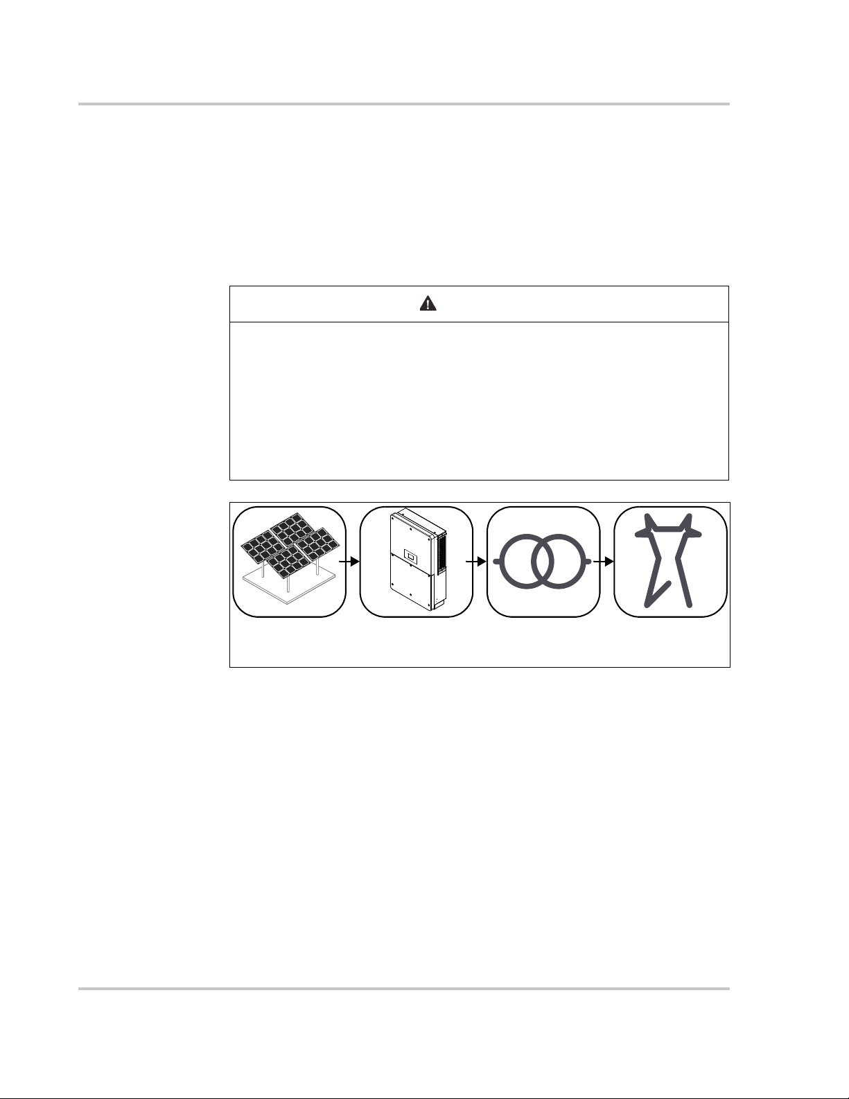
WARNING
PV Array CL-60 Transformer Utility Grid
TT, TN-C, TN-S,
TN-C-S, IT
without grounding
Conext CL-60
The Conext CL-60 (also referred to as CL-60 PV Inverter) is a transformerless
three-phase PV string inverter that is designed to be an integral part of any utility
grid-connected PV Power System.
The Conext CL-60 is designed to convert DC power generated from the PV array
into AC power that is compatible with utility grade AC power. The following
diagram illustrates its fundamental application.
ELECTRICAL SHOCK HAZARD
• Do not connect the inverter to a PV string where the positive and negative
terminals of the PV strings need to be grounded.
• Do not connect any local load between the inverter and the AC circuit
breaker.
• Use the inverter ONLY in a grid-connected PV system.
Failure to follow these instructions can result in death or serious injury.
Figure 1-1 Fundamental Application
1–2 975-0768-01-01 Revision B
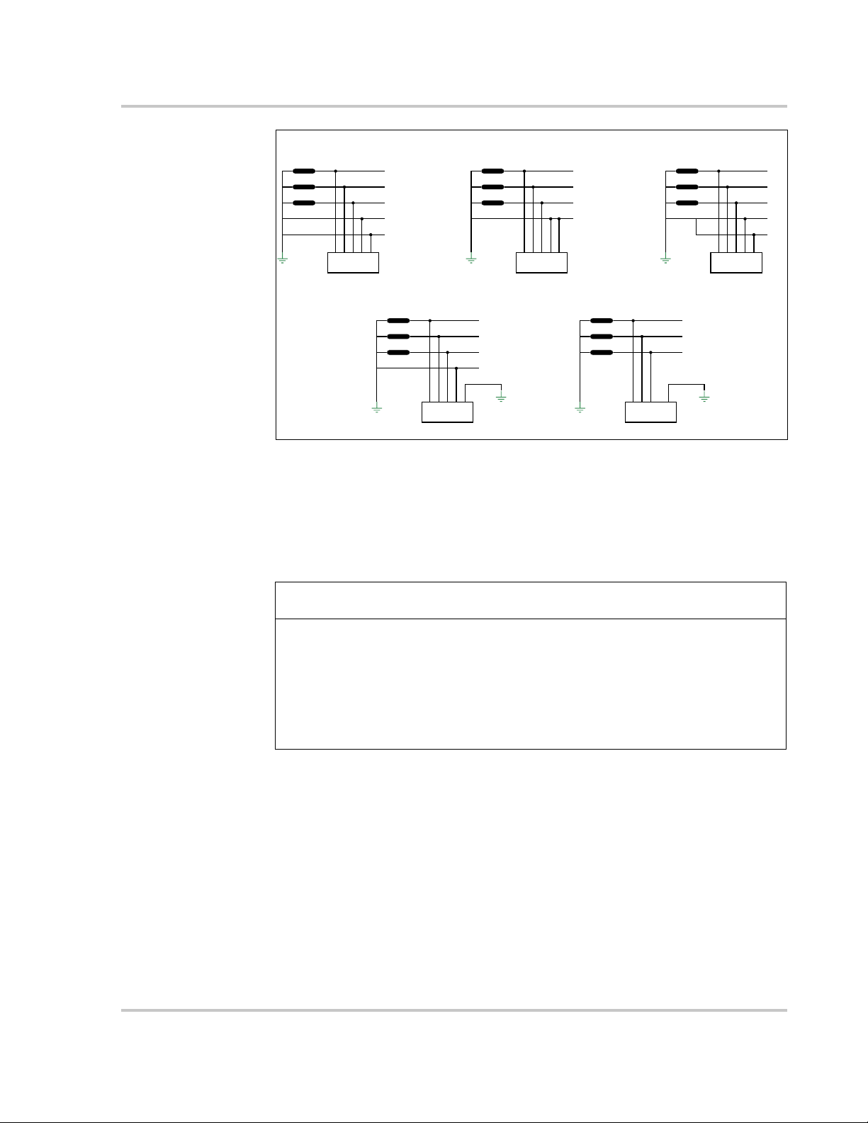
Figure 1-2 Type of Grid Connections
L1
L2
L3
N
PE
CL 60
transformer
TT
L1
L2
L3
N
PE
PE
CL 60
transformer
TN-S
L1
L2
L3
N
PE
PE
CL 60
transformer
TN-C-S
L1
L2
L3
PEN
PE
CL 60
transformer
TN-C
L1
L2
L3
PE
CL 60
transformer
IT
NOTICE
Conext CL-60
Grid Connection
Conditions
More than one CL-60 PV Inverter can be connected to the PV system if the total
capacity of the PV system (PV array) exceeds the capacity of a single inverter.
Each inverter in the multiple setup connects individually to a PV string at the
inverter’s DC input side. Then the inverter’s AC output side connects to the AC
mains (the grid).
EQUIPMENT DAMAGE
Follow local regulations when installing a connection to a either a TT or TN
system. An additional external Type B RCD (residual current detection) device
rated 300 mA continuous may be required and combined with additional
automatic disconnect devices.
Failure to follow these instructions can result in equipment damage.
975-0768-01-01 Revision B 1–3
Introduction
1
2
4
3
3
6
8
7
3
3
5
9
10
11
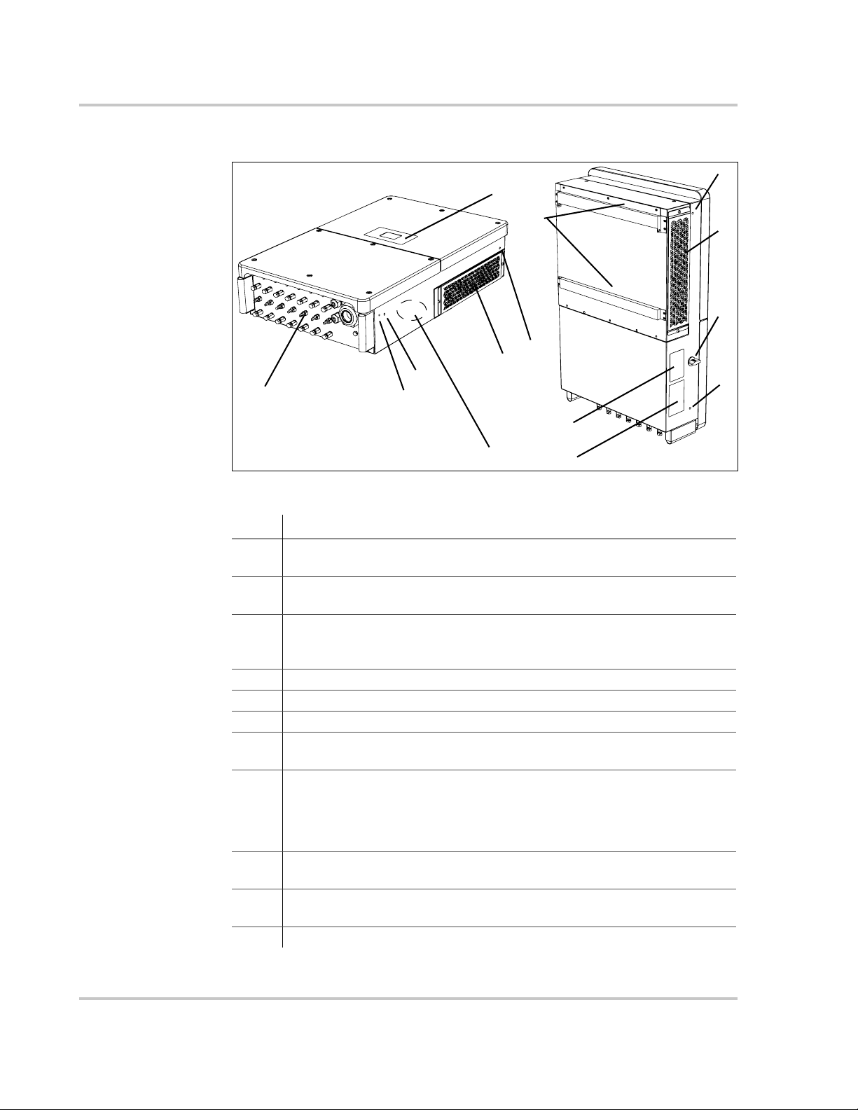
Physical Features
Figure 1-3 CL-60 Components (CL-60E shown)
Item Description
1 LCD Display is the main HMI for viewing operational information and
changing parameter values for settings.
2 Electrical connection area includes the DC terminals, AC terminals,
and RS-485 communication terminals.
3 Hole Inserts for Screw-in Handles are used for seating the screw-in
handles. The handles are used for moving, handling, and mounting the
PV Inverter.
4 PE second terminal
5 Air ventilation is equipped with fans to draw hot air out.
6Backplate is used to hang the PV Inverter onto the wall.
7 Fans (3x) with protective grate are used for forced-air cooling inside
the inverter enclosure.
8 DC switch is a protective component for safely disconnecting DC
power from the PV Array but only up to the terminals.
For full disconnection, disconnect power from the PV disconnect
device. See “Single Line Diagram for CL-60” on page xi.
9 Warning Label Read before installing, maintaining, and servicing the
10 Rating Label contains the unit’s electrical specifications and regulatory
11 CL-60A has an AC Switch in the area shown.
unit.
markings.
1–4 975-0768-01-01 Revision B
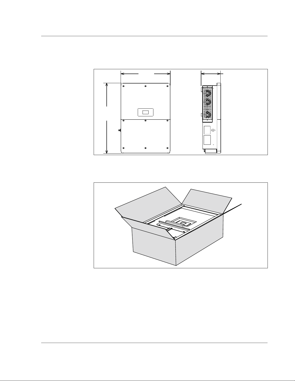
Dimensions
625 mm
24.6 in
250 mm
9.8 in
991 mm
39 in
Unit weight:
66.0 kg (CL-60E)
147 lbs (CL-60A)
Length:
1160 mm / 45.7 inWidth:
770 mm / 30.3 in
Height:
375 mm / 14.8 in
Gross weight:
76.0 kg (CL-60E)
168 lbs (CL-60A)
Inverter Dimensions
Physical Features
Figure 1-4 Conext CL-60 Dimensions (CL-60E shown)
Packaging Box Dimensions
Figure 1-5 Conext CL-60 Packaging Box Dimensions
975-0768-01-01 Revision B 1–5
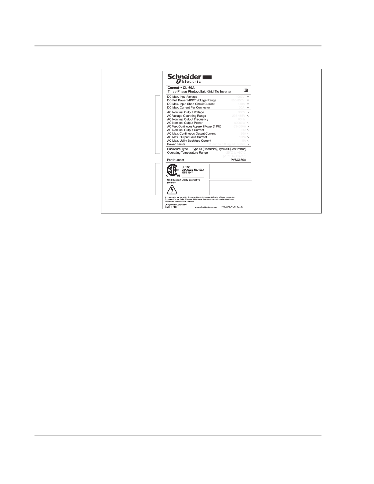
Introduction
product name
product ratings
product part number
certification and
regulatory
markings
serial number
manufacturing
date
Product Label
Figure 1-6 Example of a Conext CL-60 Product Label
1–6 975-0768-01-01 Revision B
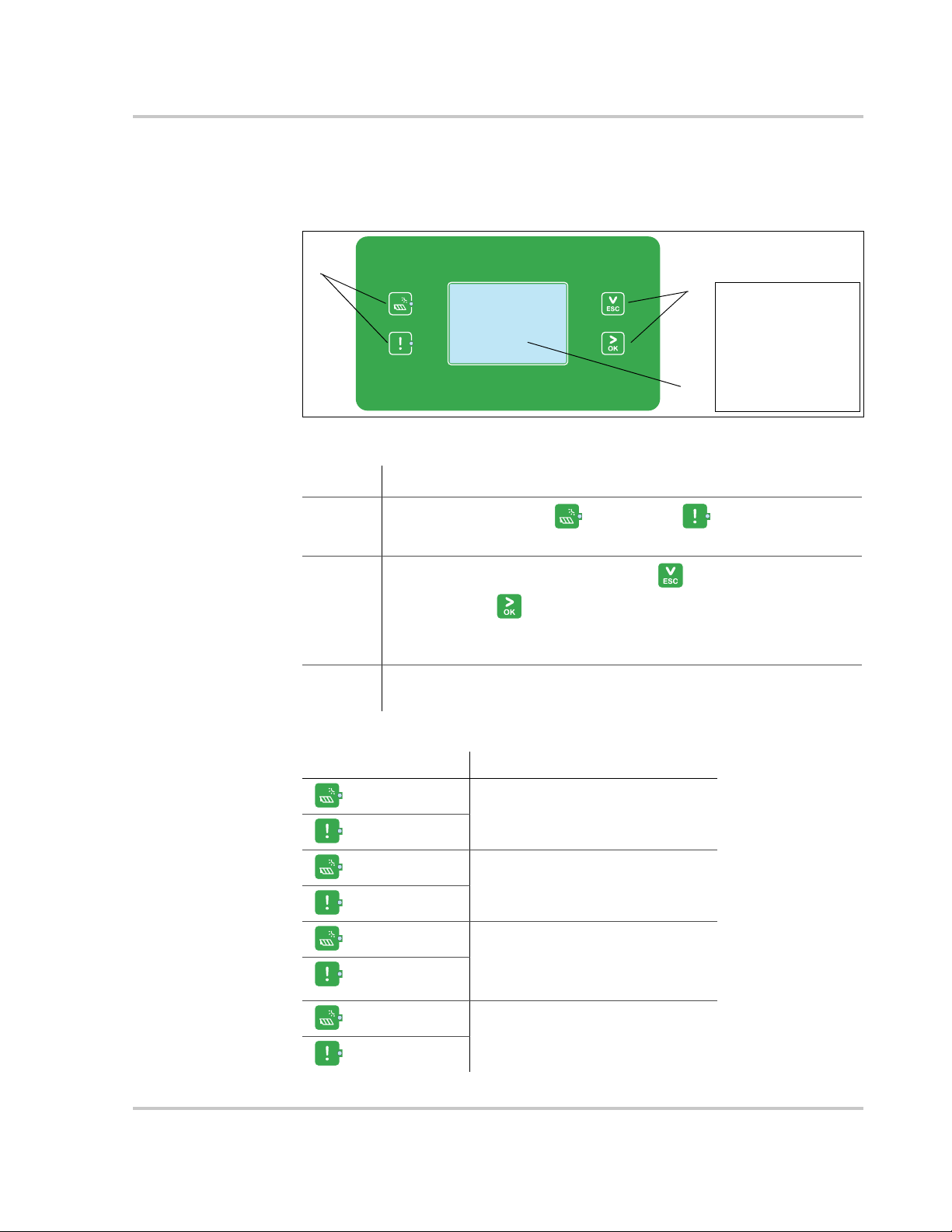
LCD Display
1
2
3
NOTE: Condensation may
appear behind the LCD
display. This occurrence is
normal in cold climate
conditions. The
condensation dissipates
soon after the unit starts
producing power or when
ambient temperature settles
above the dew point.
Physical Features
The LCD Display is the main interface of the CL-60 PV Inverter. It is made up of
two LED indicators, two buttons, and the screen itself.
Figure 1-7 LCD Display
Item Description
1
LED Indicators – RUN and ALERT .
Indicates the present operational state of the PV Inverter.
2
Selection Buttons – ESC (and down) and
OK (and next) .
Use for navigating the LCD interface, selecting settings, and
changing parameters of settings.
3 LCD Screen. Displays the present state of the PV Inverter,
operational and alarm information, and present settings.
Tab l e 1 -1 Description of LED Indicators
LED Indicators Description
RUN - On
The PV Inverter is in operation.
ALERT - Off
RUN - Off
A ground fault (or any event) is
detected or a protection feature is
ALERT - On
RUN - Off
ALERT - Off
enabled.
The PV Inverter is not in operation
or a communication fault is
detected between the DSP and
the LCD Display.
RUN - flashing
ALERT - Off
975-0768-01-01 Revision B 1–7
The PV Inverter is communicating
a warning.
Introduction
WARNING
DC Switch
The DC Switch is both the main power switch and a protective component which
is used to safely disconnect DC power between the PV array and the PV Inverter
whenever necessary to do so.
The PV Inverter operates automatically (without the need of switching On or Off)
when DC input and AC output requirements are continuously met. Turn the DC
switch to the Off position only to stop PV Inverter operation when a ground fault
condition is detected or when there is a non-ground fault condition to stop
inverter operation such as maintenance and servicing.
ELECTRIC SHOCK HAZARD
• Do not perform maintenance and servicing without totally disconnecting
the DC source from the inverter. The DC switch does not de-energize the
DC fuse circuits. The fuse circuits remain live even if the DC switch is
turned to the Off position.
• To remove power to the inverter, disconnect power from the PV disconnect
device. See “Single Line Diagram for CL-60” on page xi.
• Alternatively, to remove power to the inverter, open all MC4 type connectors
using a special tool for disconnection.
Failure to follow these instructions can result in death or serious injury.
NOTE: For CL-60A, the DC switch is provided with a lockable twisting knob to
meet the NFPA 70E standard.
1–8 975-0768-01-01 Revision B
Technical Features
LCD/RS485
DSP+CPLD
DC
L1
L2
L3
N
PE
NL3L2L1
PE
DC
DC In
+-
+-
NL3L2
L1
PE
DC
DC In
+-
+-
L1 L2 L3
N
L1 L2 L3
N
DC EMI
Filter
DC bus
Inversion
circuit
AC
EMI
Filter
AC
Reactor
Relay
Fan
AC SPD
DC
switch
AC
switch
DC SPD
Current detection
DC SPD
DC
switch
DC fuse
DC fuse
Auxilia ry
power circuit
Current detection
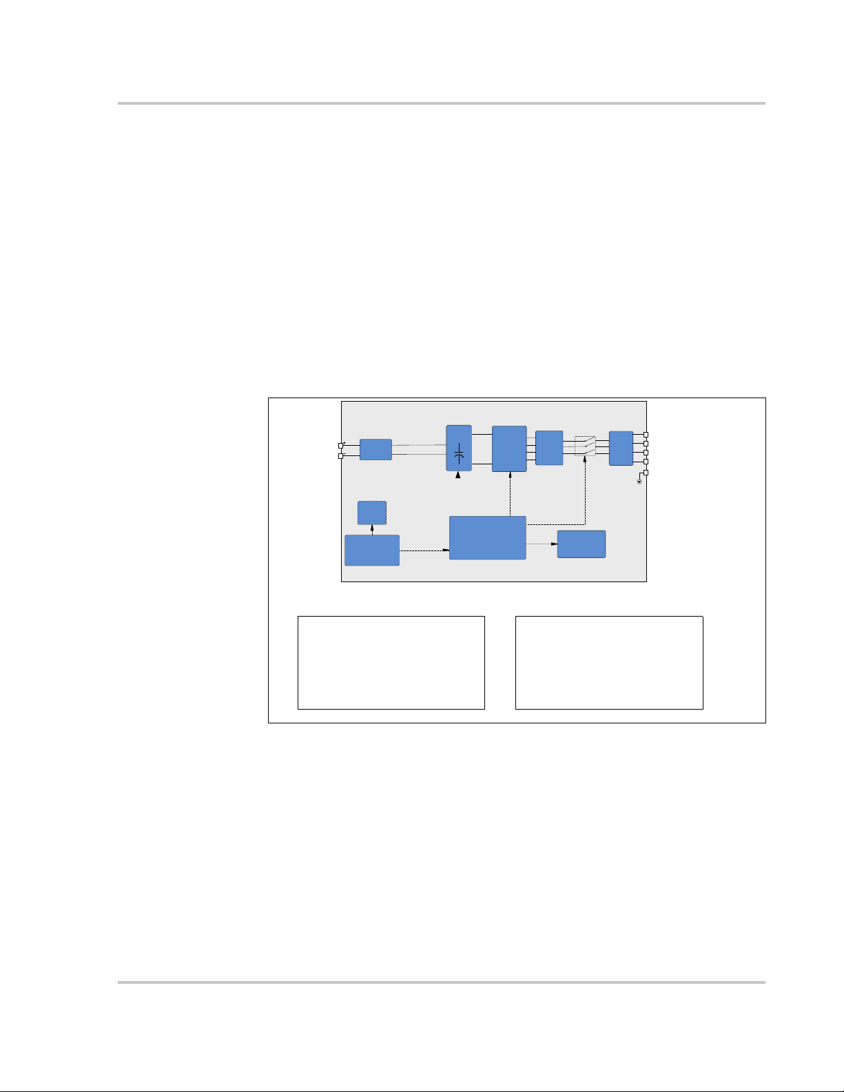
CL-60E Wiring Box contents CL-60A Wiring Box contents
- DC switch
- 14 strings
- 15A fuses in positive polarity
- monitoring in negative polarity
- type 2 DC SPD
- type 3 AC SPD
- DC switch
- 8 inputs (1@ for 2 combined strings)
- 30A fuses in both polarities
- type 2 DC SPD
- type 3 AC SPD
- AC switch
CL-60 Circuit Diagram
Figure 1-8 shows the main circuit of the PV Inverter.
Maximum Power Point Tracking (MPPT) is utilized to optimize harvesting DC
power from the PV array with different PV input conditions.
The PV Inverter circuit converts DC power into AC power and feeds it to the utility
grid through the inverter’s AC terminal. The protection circuit is equipped to
ensure the device’s safe operation and personal safety.
The DC switch is used to disconnect DC power from the PV Array safely.
The inverter provides standard RS-485 ports for communication.
Technical Features
Figure 1-8 Conext CL-60 Circuit Diagram
Standard Features
Inverter Function The device’s main function is to convert DC current into grid-
compatible AC current then feed this current into the grid.
Data Storage and LCD Display The onboard memory stores information such
as fault detection and displays them on the screen of the integrated LCD Display.
Device Configuration The LCD Display provides the main interface for
accessing device settings and changing them for optimal operation of the
inverter.
975-0768-01-01 Revision B 1–9

Introduction
Communication Interface Features a standard RS-485 port which can be
connected with a monitoring device such as a power meter,
Protection Features The unit is equipped with the following features for
preventing inverter damage, other equipment damage, and personal injury
hazards.
• Short-circuit protection
• Ground insulation resistance detection
• Inverter output voltage monitoring
• Inverter output frequency detection
• Residual current protection
• DC injection of AC output current surveillance
• Anti-islanding protection
• Ambient temperature monitoring
• DC over-voltage protection
• Over-current protection
• Power module over-temperature protection
• Fan failure protection
• Arc fault detection and protection (for CL-60A)
Derating Feature
Output derating is a way to protect the inverter from overload or potential fault
detections. These situations prompt the PV Inverter to initiate power derating:
• Altitude higher than 3000 meters
• Internal temperature is too high (including ambient temperature and
internal components temperature)
NOTE: For example, installing the inverter in an enclosed
space may hasten derating.
• Grid voltage is too low
• External power class adjustment
• Grid frequency is too high (see NOTE)
NOTE: Valid only when the country selected is DE or IT.
• High grid voltage with a simultaneous low PV voltage.
Power Limit Setting Inverter output power can be adjusted via the LCD
Display or a remote grid dispatch from the utility company. The corresponding
operating state will be displayed on the LCD screen.
1–10 975-0768-01-01 Revision B
Technical Features
Vmpp=600V
Vmpp=710V
Vmpp=850V
40 45
50 55 60
40
45
50
55
60
Ambient Temp (°C)
Apparent Power˄KVA˅
CL-60E Temperature Derating Curve
˄Vac=400V˅
35
66
Vmpp=600V
Vmpp=710V
Vmpp=850V
40 45
50 55 60
40
45
50
55
60
Ambient Temp (°C)
Apparent power˄KVA˅
CL-60A Temperature derating curve
˄Vac=380V˅
35
63.36
NOTE: The lower limit of the over-temperature derating is 75% of nominal power.
If both the module and internal temperatures reach power derating conditions, the
inverter will derate the power output based on the lower temperature between the two.
not to scale
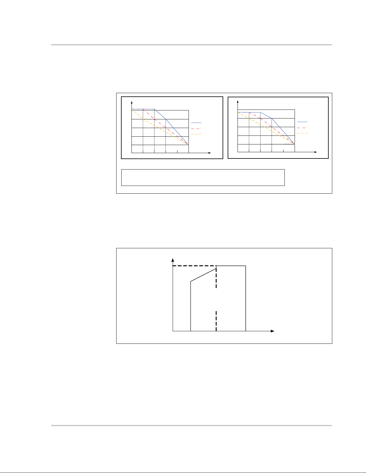
V
min
V
max
P
n
215V
Working area
P[Vmin…266V] = Pn × (Vgrid / 230V)
Over-temperature Derating High ambient temperature, a blocked fan, or poor
ventilation will initiate inverter power derating.
When the temperature inside the unit exceeds the upper limit, the inverter will derate
its power output until the internal temperature drops within the allowable range.
Figure 1-9 Over-Temperature Derating
Grid Under-voltage Derating When grid voltage is low, the inverter will derate
the output power to make sure the output current is within the allowable range.
Once the grid voltage is within Vmin (215V), the inverter will derate its output
power.
Figure 1-10 Grid Under-Voltage Derating
975-0768-01-01 Revision B 1–11
Introduction
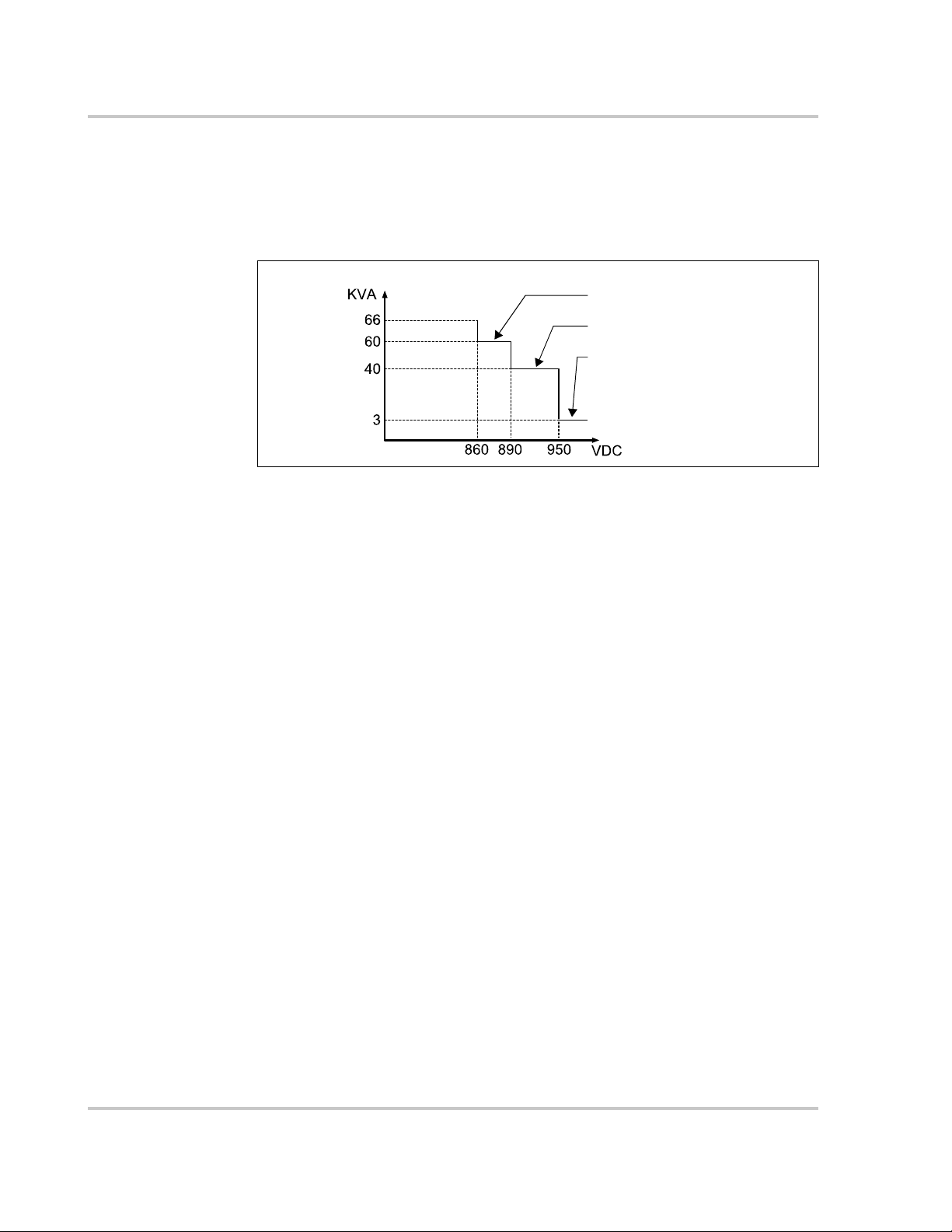
Output voltage max when PV voltage < 860
Output voltage max when PV voltage < 890
Output voltage max when PV voltage < 950
PV Over-voltage Derating The inverter regularly scans the PV voltage every 25
minutes and forces the PV to derate to test whether the maximum power point is
less than 860 volts.
At 66 KVA, if the maximum power point is higher than 860 volts, then the inverter
will return to the higher voltage limit before it starts derating.
Figure 1-11 PV Over-Voltage Derating
1–12 975-0768-01-01 Revision B

2 Installation
Chapter 2 contains information about:
• Pre-Installation
• Installation
975-0768-01-01 Revision B 2–1

Installation
Pre-Installation
Before installing the Conext CL-60, read all instructions and cautionary markings
in this Guide.
NOTE: Obtain all necessary permits prior to starting the installation.
Installations must meet all local codes and standards. Installation of this
equipment should only be performed by skilled personnel such as qualified
electricians and Certified Renewable Energy (RE) System installers.
Planning the Installation
• Read this entire chapter before beginning the installation. It is important to
plan the installation from beginning to end.
• Assemble all tools and materials needed for the installation.
2–2 975-0768-01-01 Revision B

Installation
DANGER
ABCD
EF G H I
NOTE: Use only these
fasteners when mounting
the inverter.
ELECTRIC SHOCK AND FIRE HAZARD
• Do not connect the PV Inverter to a live power source prior to cabling and
wiring found in Chapter 3, “Electrical Connections”. The inverter can be
energized from two sources namely, DC from the PV array and AC from the
grid.
• Do not connect any powered device to the PV Inverter during installation.
Failure to follow these instructions will result in death or serious injury.
What’s In The Box
The following materials are supplied in the Conext CL-60 package:
First Row • A CL-60 unit
• B Wall-mounting backplate
• C CL-60 USB drive contains the CL-60 Owner’s Guide
• D CL-60 Quick Install Guide including extra multi-lingual product labels
Second Row • E Metal frame M10x45 fasteners (6x)
• F M4x16 backplate screws (2x)
• G Screw-in handles (4x)
• H MC4 DC cable connectors (14x pairs) for the CL-60E
Amphenol
• I AC cable gland
®
H4 DC cable connectors (8x pairs) for the CL-60A
Installation
Figure 2-1 What’s In the Box
975-0768-01-01 Revision B 2–3

Installation
DANGER
Material and Tools
The following materials and tools are not supplied but are required to complete
the installation:
• Personal protective equipment (PPE)
• Screwdriver and drill set (powered and/or manual)
• Six (M10x65) screws (for fastening wall-mounting backplate to the wall)
• Calibrated professional digital multimeter
• Crimping tool from Multi-Contact (http://www.multi-contact-usa.com/ for CL-
Location Information
ELECTRIC SHOCK, EXPLOSION, OR ARC FLASH HAZARDS
• Apply appropriate personal protective equipment (PPE) and follow safe
• This equipment must only be installed and serviced by qualified electrical
• Never energize the inverter with the covers removed.
• Do not open fuse holders under load. The fuse must be de-energized from
• The inverter is energized from multiple sources. Before removing covers
• Always use a properly rated voltage sensing device to confirm all circuits
• Replace all devices and covers before turning on power to this equipment.
• The DC conductors of this photovoltaic system are ungrounded and may
Failure to follow these instructions will result in death or serious injury.
60E) and Amphenol (https://www.amphenol.com/ for CL-60A)
electrical work practices.
personnel.
all sources before servicing.
identify all source, de-energize, lock-out, and tag-out and wait 10 minutes.
See “Lock-Out Tag-Out (LOTO) Procedure” on page xi.
are de-energized.
be energized.
Environment The CL-60 is IP65 rated (CL-60E) and Type 4X rated (CL-60A). It is suitable for
outside installation.
The ambient temperature should be within the range of –25 to 60 °C (–13 to
140 °F) to prevent automatic power derating in over-temperature conditions.
Relative humidity at the installation site can be from 0 to 100%.
Allow for at least 600 mm (~24 inches) clearance on all sides of the inverter.
When installing another inverter next to it (or several inverters around it), increase
the clearance between inverters from all sides to 800 mm (~32 inches).
See Figure 2-2, “Clearances and Ambient Temperature” on page 2–5.
2–4 975-0768-01-01 Revision B

Fire Safety
600mm
~24”
800mm
~32”
600mm
~24”
600mm
~24”
-13 +140 °F
-25 +60 °C
between
CL-60s
between other
objects
WARNING
Installation
Figure 2-2 Clearances and Ambient Temperature
IGNITION AND FIRE HAZARD
• This equipment is not ignition protected. To prevent fire or explosion, do
not install this product in locations that require ignition-protected
equipment. This includes any confined space containing lead acid
batteries, or flammable chemicals such as, natural gas (NG), liquid
petroleum gas (LPG) or gasoline (Benzine/Petrol).
• Do not install in a confined space with machinery powered by flammable
chemicals, or storage tanks, fittings, or other connections between
components of fuel or flammable chemical systems.
• Do not install the CL-60 on a wooden/plastic/plaster wall.
• Do not install the CL-60 near readily flammable materials such as cloth,
paper, straw, or plastic sheeting. Keep flammable materials from all sides
including the front of the CL-60.
Failure to follow these instructions can result in death or serious injury.
Flammable or combustible materials are defined as “any material containing
wood, compressed paper, cellulose, plant fibers, plastics, liquids, or other
material that will ignite and burn, whether flame-proofed or not” according to
NFPA 70E. Flammable liquids are defined as “any liquid whose flash point does
not exceed 100 °F (38 °C).” Examples of flammable liquids are gasoline,
methanol, and ether.
When choosing a wall or flat surface to install the CL-60, choose a wall or flat
surface that is not considered a flammable material such as concrete, brick, or
metal.
975-0768-01-01 Revision B 2–5

Installation
CAUTION
WARNING
Handling
Precautions
HEAVY LOAD HAZARD
• Do not handle and lift the unit by yourself. Use two people to move, lift,
and mount the unit.
• Always use proper lifting techniques during installation including using the
provided screw-in handles.
• When handling the inverter, install all four screw-in handles to both sides of
the inverter first and make sure they are seated correctly in their slots.
• Do not substitute the screw-in handles with something else. Use only the
provided screw-in handles.
• Use mechanical or motorized hand trucks and/or lifts whenever possible
to aid in proper handling.
Failure to follow these instructions can result in moderate or minor injury.
Storage
Considerations
Location Hazards In order to avoid other potential hazards follow the instructions in the WARNING
If the inverter cannot be installed immediately after delivery at the installation site,
consider storing the inverter inside its original carton and setting it aside away
from potential damage. For more guidelines, see “Storage Information” on
page x.
below.
ELECTRICAL SHOCK, FIRE, AND PHYSICAL INJURY HAZARD
• Install the CL-60 on a concrete wall or metal frame which can support the weight
(66 kg (CL-60E) /147 lbs(CL-60A)) of the unit over time. When installing multiple
units, make sure the wall or metal frame can support the total weight of the units
over time.
• Install the unit upright at 90° vertical angle in relation to the floor. The unit
can also be installed horizontally flat and parallel to the floor. When
installing on a slope, the top of the unit must be higher than its bottom.
• Install the unit at the recommended height of 1.2 m (4 ft.) for easy access
to the terminals and ports.
• Avoid installing the CL-60 in completely uncovered locations where
persistent rain and moisture spray can eventually penetrate the enclosure.
Install under a covered structure.
• Install a separate and external surge protection device to protect the CL60’s power module and communication ports.
Failure to follow these instructions can result in death or serious injury.
2–6 975-0768-01-01 Revision B

Installation
NOTICE
90°
<90°
0°
Not allowed
Allowed
EQUIPMENT DAMAGE
• Avoid installing the CL-60 in direct sunlight or near other heat sources like
the exhausts of inverters and generators, steam exhausts from boilers and
dryers, and engine compartments. Install in shaded locations.
• Choose a location and an installation layout that minimizes potentially
induced voltage spikes that might damage the electronics.
Failure to follow these instructions can result in equipment damage.
Figure 2-3 Mounting Orientations
975-0768-01-01 Revision B 2–7

Installation
NOTE: To install the inverter onto a
concrete wall, use the recommended
M10x65 screws (not supplied).
6x M10
NOTE: Whenever possible, use only
the supplied fasteners when mounting
the inverter.
26 mm
~1 in
425 mm
~16.7 in
524 mm
~20.6 in
544 mm
~21.4 in
32 mm
~1.2 in
2x M4x7
74 mm
~2.9 in
90 mm
~3.5 in
512 mm
~20.2 in
DANGER
Install and Mount the CL-60
Figure 2-4 Wall-mounting Backplate Dimensions
To install on a concrete or brick wall in an upright position:
1. Remove the wall-mounting backplate and the two M4x12 backplate screws
from the CL-60 packaging.
2. Follow all preceding precautions and warnings starting on page 2–3.
3. Unpack the backplate from the box and use the backplate to mark the
location of the holes on the wall. See Figure 2-5, “Mark and Pre-drill Wall” on
page 2–9.
EXPLOSION HAZARD
Check that there are no plumbing or gas pipes or electrical conduits behind
the wall when marking for holes and before drilling.
Failure to follow these instructions will result in death or serious injury.
2–8 975-0768-01-01 Revision B

Installation
4. Pre-drill the mounting surface, if necessary. See Figure 2-5, “Mark and Predrill Wall” on page 2–9.
Figure 2-5 Mark and Pre-drill Wall
5. Unpack the screw-in handles and install them as shown. Screw in the
handles until they are fully seated in the inserts. See Figure 2-6, “Install
Screw-in Handles” on page 2–9.
Figure 2-6 Install Screw-in Handles
6. Fasten the wall-mounting backplate to the wall with six M10x65 screws (not
supplied). Use a torque of 35 Nm (25.8 lbf-ft) to fasten the screws and the
backplate.
975-0768-01-01 Revision B 2–9

Installation
use the handles to
mount the inverter
to the backplate
after hanging the inverter to the
backplate, lock it with the two M4 screws
(supplied)
for illustration
purposes only
7. Mount (hang) the inverter manually onto the backplate.
Figure 2-7 Mounting the CL-60
8. Lock the inverter to the backplate by fastening the two screws (M4x16) as
shown. See Figure 2-7.
9. Remove the screw-in handles from the sides of the inverter and store them
away from the top of the inverter or inside the inverter enclosure.
2–10 975-0768-01-01 Revision B

Installation
backplate
bolt (M10x45)
metal frame
hex nut (M10)
spring washer
flat washer
NOTE: Whenever possible, use only
the supplied fasteners when mounting
the inverter.
To install on a metal frame in an upright position:
1. Remove the backplate, its corresponding metal frame fasteners, and the two
M4x12 backplate screws from the CL-60 packaging. Use only the provided
metal frame fasteners for attaching to a metal frame structure.
2. Follow all preceding precautions and warnings starting on page 2–3.
3. Use the backplate to mark the metal frame with the location of the holes to be
drilled. See Figure 2-8.
4. Pre-drill the mounting surface, if necessary. See Figure 2-8.
Use a drill bit appropriate for a bolt of size M10.
Figure 2-8 Mark and Pre-drill Metal Frame
5. Unpack the screw-in handles and install them as shown. Screw in the
handles until they are fully seated in the inserts. See Figure 2-6, “Install
Screw-in Handles” on page 2–9 for an illustration.
6. Fasten the backplate to the metal frame using the metal frame fasteners that
came with the CL-60 packaging. Use a torque of 35 Nm (25.8 lbf-ft) to fasten
the nut and the backplate.
Figure 2-9 Securing the Backplate to the Metal Frame
7. Mount (hang) the inverter manually onto the backplate. See Figure 2-7,
“Mounting the CL-60” on page 2–10 for a similar illustration.
8. Lock the inverter to the backplate by fastening the two screws (M4x16). See
Figure 2-7, “Mounting the CL-60” on page 2–10 for a similar illustration.
9. Remove the screw-in handles from the sides of the inverter. See Figure 2-7,
“Mounting the CL-60” on page 2–10 for a similar illustration.
975-0768-01-01 Revision B 2–11

Installation
WARNING
450mm
~18”
ground (floor)
for illustration
purposes only
To install on a horizontally flat metal or concrete surface:
ELECTRICAL SHOCK AND FIRE HAZARD
• Do not install the unit within 800 mm (31.5 inches) of vegetation (weeds,
grass) and other flammable materials. See the definition of flammable
materials in “Fire Safety” on page 2–5.
• Provide a minimum distance of 450 mm (~18 inches) between the PV
Inverter’s back and the ground (the floor).
• Install the backplate even though the inverter is not going to hang on it.
The backplate provides stability for the inverter.
• Be careful to check that there are no plumbing or gas pipes or electrical
conduits underneath the flat surface you are marking for holes.
Failure to follow these instructions can result in death or serious injury.
1. Remove the wall-mounting backplate and its corresponding fasteners from
the CL-60 packaging.
2. Follow all preceding precautions and warnings starting on page 2–3.
3. Unpack the backplate from the box and use the backplate to mark the flat
surface with the location of the holes to be drilled. See Figure 2-5, “Mark and
Pre-drill Wall” on page 2–9.
4. Pre-drill the mounting surface, if necessary. Use a drill bit appropriate for a
bolt of size M10.
Figure 2-10 Ground Clearance and Fastening the Backplate
5. Unpack the screw-in handles and install them as shown. Screw in the
handles until they are fully seated in the inserts. See Figure 2-6, “Install
Screw-in Handles” on page 2–9.
2–12 975-0768-01-01 Revision B

Installation
for illustration
purposes only
450 mm
~18 in.
6. Fasten the backplate to the flat metal surface (using the metal frame
fasteners that came with the CL-60 packaging, if necessary) or concrete
surface (using M10x65 screws which are not provided). Use a torque of 35
Nm (25.8 lbf-ft) to fasten the nut and the backplate.
7. Lay the inverter manually onto the backplate to lock its position. Handle the
inverter by the screw-in handles.
Figure 2-11 Mounting to a Flat Surface
8. Lock the inverter to the backplate by fastening the two screws (M4x16). See
Figure 2-7, “Mounting the CL-60” on page 2–10 for a similar illustration.
9. Remove the screw-in handles from the sides of the inverter. See Figure 2-7,
“Mounting the CL-60” on page 2–10 for a similar illustration.
975-0768-01-01 Revision B 2–13

Installation
WARNING
within 90º angle
for illustration
purposes only
top
bottom
bottom
top
To install on a sloped metal or concrete surface:
Examples of sloped surfaces are rooftops and uneven terrain.
ELECTRICAL SHOCK AND FIRE HAZARD
• Do not install the unit on a slope in which the top part of the inverter is
lower than its bottom. See Figure 2-12 below.
• Be careful to check that there are no plumbing or gas pipes or electrical
conduits underneath the surface you are marking for holes.
Failure to follow these instructions can result in death or serious injury.
◆ Follow the same procedures in the previous section “To install on a
horizontally flat metal or concrete surface:” on page 2–12.
Figure 2-12 Installing on Sloped Surfaces
2–14 975-0768-01-01 Revision B

Torq u e Va l u e s
CAUTION
NOTICE
Installation
FIRE HAZARD
Tighten fasteners such as screws, nuts, bolts, and cable glands (used for
routing field wiring and current carrying cable) according to the
recommendations in the table below. Incorrect torque may cause a fire.
Failure to follow these instructions can result in moderate or minor injury.
EQUIPMENT DAMAGE
Tighten fasteners such as wall screws, metal frame nuts, and panel screws
according to the recommendations in the table below. Over torquing may
damage the head of the fastener. Under torquing may loosen the installation
over time.
Failure to follow these instructions can result in equipment damage.
Tab l e 2 -1 Summary of Torque Values
Type Description Nm (IEC) lbf-ft (NA)
cable gland for communication cables
such as RS-485 Ethernet
cable
cable gland for smaller AC cable 12–13 8.8–9.6
cable gland for larger AC cable 16–17 11.8–12.5
connector screw RS-485 wire connector 0.2 0.15
fastener transparent protection
panel
fastener lower enclosure panel 4.3 ±0.2 3.2 ±0.15
fastener to lock the CL-60 unit to
the mounting backplate
fastener (metal) metal frame-mounting
backplate nut
fastener (wall) wall-mounting backplate
expansion
terminal gland MC4 DC terminal 2.5–3 1.8–2.2
terminal screw AC terminal block 4.3 ±0.2 3.2 ±0.15
terminal screw PE (ground) terminal
block
3.75 2.8
0.8 ±0.1 0.6 ±0.1
2.7–4.8 2–3.5
35 25.8
35 25.8
4.3 ±0.2 3.2 ±0.15
975-0768-01-01 Revision B 2–15

Installation
•THIS PAGE INTENTIONALLY BLANK•
2–16 975-0768-01-01 Revision B

3 Electrical
Connections
Chapter 3 contains information about:
• Precautions
• Cabling and Wiring
• Communication Connection
975-0768-01-01 Revision B 3–1

Electrical Connections
Precautions
Before connecting the Conext CL-60 to electrical cables, wires, and
communication cables, read all instructions and cautionary markings in this
Guide.
NOTE: Obtain all necessary permits prior to starting the installation.
Installations must meet all local codes and standards. Installation of this
equipment should only be performed by skilled personnel such as qualified
electricians and Certified Renewable Energy (RE) System installers.
Planning the Electrical Connections
• Read this entire chapter before making electrical connections to and from the
unit. It is important to plan the installation from beginning to end.
• Assemble all tools and materials needed for the installation.
3–2 975-0768-01-01 Revision B

Cabling and Wiring
DANGER
ELECTRIC SHOCK AND FIRE HAZARD
• All wiring must be done by qualified personnel to ensure compliance with
all applicable installation codes and regulations.
• Do not connect the PV Inverter to a live power source prior to finishing all
cabling and wiring. The inverter can be energized from two sources
namely, DC from the PV array and AC from the grid.
• Do not connect any powered device to the PV Inverter during cabling and
wiring.
Failure to follow these instructions will result in death or serious injury.
Material and Tools
The following materials and tools are not supplied but are required to complete
the installation:
• AC power cable (4-wire/5-wire)
• Crimping tool from Multi-Contact (http://www.multi-contact-usa.com/ for CL60E) and Amphenol (https://www.amphenol.com/ for CL-60A)
• DC power cable (color-coded - red for (+), black for (-))
• RS-485 cable(s) for Modbus/RS-485 device connections
• Wire stripper, RJ45 crimper, connector tool spanner
• Screwdriver set, pliers
• CAT6/5/e network cable(s) for Modbus/RS-485 PV Inverter and Ethernet TCP/
IP connections
• Laptop computer (PC or Mac)
• Network router for LAN and internet connectivity
Cabling and Wiring
Once the Conext CL-60 is installed at the site, it is now ready to be connected to
the PV array and the utility grid.
975-0768-01-01 Revision B 3–3

Electrical Connections
DANGER
ELECTRIC SHOCK, EXPLOSION, OR ARC FLASH HAZARDS
• Apply appropriate personal protective equipment (PPE) and follow safe
electrical work practices.
• This equipment must only be installed and serviced by qualified electrical
personnel.
• Never energize the inverter with the covers removed.
• Do not open fuse holders under load. The fuse must be de-energized from
all sources before servicing.
• The inverter is energized from multiple sources. Before removing covers
identify all source, de-energize, lock-out, and tag-out and wait 10 minutes.
See “Lock-Out Tag-Out (LOTO) Procedure” on page xi.
• Always use a properly rated voltage sensing device to confirm all circuits
are de-energized.
• Replace all devices and covers before turning on power to this equipment.
• The DC conductors of this photovoltaic system are ungrounded and may
be energized.
Failure to follow these instructions will result in death or serious injury.
3–4 975-0768-01-01 Revision B

Terminal and Cable Entry Points (for CL-60E)
1
2
4
3
5
678
910
Front
View
Bottom
View
The CL-60E’s electrical connection terminals are located inside the inverter
wiring box and the cable entry points are at the bottom of the unit.
Cabling and Wiring
Figure 3-1 Terminals and Cable Entry Points
Tab l e 3 -1 Description of Terminals and Cable Entry Points
No. Description No. Description
1 DC switch 6 DC input MC4 terminals
2 DC SPD 7 Communication cable glands
3 AC crimping terminal 8 AC cable gland (large)
4 DC fuse board 9 Second PE (ground) location
5 Communication circuit board 10 Waterproof air valve
975-0768-01-01 Revision B 3–5

Electrical Connections
1
23
4
6
8910
1112
Front
View
Bottom
View
5
7
Terminal and Cable Entry Points (for CL-60A)
The CL-60A’s electrical connection terminals are located inside the inverter
wiring box and the cable entry points are at the bottom of the unit.
Figure 3-2 Terminals and Cable Entry Points
Tab l e 3 -2 Description of Terminals and Cable Entry Points
No. Description No. Description
1 DC switch 7 Communication circuit board
2 DC SPD 8 DC input Amphenol H4
3 Arc fault circuit interrupter 9 Communication cable glands
4 AC crimping terminal 10 AC cable gland (large)
5 AC switch 11 Second PE (ground) location
6 DC fuse board 12 Waterproof air valve
terminals
3–6 975-0768-01-01 Revision B

AC Side Cable Connection
NOTICE
AC Side Requirements
NOTE: Connection to the utility grid must be done only after receiving approval
from the local company.
Before connecting to the grid, verify that both the grid voltage and frequency
meet the requirements of the CL-60’s voltage and frequency settings. Contact the
local utility company for a solution if the grid does not meet the specifications. For
information on the settings, see “Product Specifications” on page 8–2.
AC Circuit Breaker
An independent three- or four-pole circuit breaker must be installed downstream
from the inverter before the grid connection. This is to ensure that the inverter can
be disconnected safely from the grid.
Inverter Recommended
CL-60E
CL-60A
Cabling and Wiring
AC circuit breaker
120A
EQUIPMENT DAMAGE
• Do not connect multiple PV Inverters to a single circuit breaker.
• Do not connect loads between the PV Inverter and the circuit breaker.
Failure to follow these instructions can result in damage to the inverter
and other connected equipment.
Residual Current Device
With an integrated comprehensive residual current monitoring component, the
inverter is capable of distinguishing a ground fault current from normal
capacitive leakage current. This allows the inverter to disconnect from the grid as
soon as the ground fault is detected.
975-0768-01-01 Revision B 3–7

Electrical Connections
L1
L2
L3
N
PE
inverter 1 inverter 2 inverter n
...
U2
V2
W2
U1
V1
W1
N
inverter 1 inverter 2 inverter n
...
low voltage high voltage
MV Transformer
Multiple Inverters in Parallel Connection
Follow either of the two scenarios when attempting to connect several inverters in
parallel to the grid.
Scenario 1 Several inverters are in parallel connection to the 3-phase low voltage grid.
Requirements If the number of the grid-connected PV Inverters exceed 40,
contact a local Schneider Electric Sales Application Engineer (SAE).
Scenario 2 Several inverters are in parallel connection to the low voltage side of the MV
transformer. The high voltage side is connected to the MV grid.
3–8 975-0768-01-01 Revision B
Requirements If the number of the grid-connected PV Inverters exceed 40,
contact a local Schneider Electric Sales Application Engineer (SAE).
The nominal power of the MV transformer’s low voltage side matches the
inverter’s output power.
NOTE: It is recommended to use a transformer with a short circuit impedance
of less than 6%.

Grid Connection
230 235 240 245 250 255 260
0
0.5
1
1.5
2
Max. grid impedance [Ohm]
AC voltage without loads [V]
265
Cabling and Wiring
The AC terminal block on the bottom of the CL-60E inverter accommodates an
AC connection for a 3-phase-5-wire grid connection (L1, L2, L3, N and PE).
The AC terminal block on the bottom of the CL-60A inverter accommodates an
AC connection for a 3-phase-4-wire grid connection (L1, L2, L3, and GND).
AC Cable Requirements
Select AC cables according to the following factors:
• Grid impedance should correspond to the specifications below to avoid
accidental short-circuit or output power derating.
• When calculating voltage drop, a cable with a higher cross section area
could be selected to ensure power loss within a 1% limit. Check that the
AC cable outer diameter is suitable for the AC terminals of the inverter.
• Ambient temperature
• Cable layout (that is, inside wall, underground, free air, etc.)
• UV resistance
• Cable resistance / length
975-0768-01-01 Revision B 3–9

Electrical Connections
DANGER
AC Cable
Connection
To connect the PV Inverter to the grid:
ELECTRIC SHOCK, EXPLOSION, OR ARC FLASH HAZARD
• Apply appropriate personal protective equipment (PPE) and follow safe
electrical work practices.
• This equipment must only be installed and serviced by qualified electrical
personnel.
• Never energize the inverter with the covers removed.
• Do not open fuse holders under load. The fuse must be de-energized from
all sources before servicing.
• The inverter is energized from multiple sources. Before removing covers
identify all source, de-energize, lock-out, and tag-out and wait 10 minutes.
• Always use a properly rated voltage sensing device to confirm all circuits
are de-energized.
• Replace all devices and covers before turning on power to this equipment.
• The DC conductors of this photovoltaic system are ungrounded and may
be energized.
• Do not connect to the AC circuit breaker until all inverter electrical
connections are completed.
Failure to follow these instructions will result in death or serious injury.
1. Open the AC circuit breaker (turn it OFF) and perform the “Lock-Out Tag-Out
(LOTO) Procedure” on page xi.
2. Remove the six screws on the front cover of the wiring box to access the
terminals.
3–10 975-0768-01-01 Revision B

Cabling and Wiring
1
2
34
PE
L1
L2
L3
N
For illustration
purposes only.
3. Strip the cables as shown below. Example below is for a five-wire cable.
NOTE:
For AC cables with stranded wires, use cold-press terminal lugs for
termination. Always use lugs that grip the shape of the wires on AC cables. Always
use the proper lugs according to the type of metal of the wires on AC cables.
The cross-section diameter of the AC cable must be selected carefully in order to
prevent accidental disconnections of the inverter from the grid due to high
impedance of the cable.
No. Description Remark
1 Protective layer External diameter of the cable:
Proper range 25 to 40 mm (~1 to 1.5 in)
2 Length of insulation to
24 mm (~1 in)
be stripped off
3 Insulation layer -
4 Cross section of AC
cable
Range: 25 to 95 mm
Recommended value: 50 mm
2
2
5 Type Aluminum or copper
• Use a smaller AC cable gland (supplied), if the selected AC cable has an
external diameter of between 25 to 30.5 mm (~1 to 1.25 in).
For replacement instructions, see “To replace the larger AC cable gland with
the smaller AC cable gland:” on page 3–13.
• Use a larger AC cable gland (pre-installed), if the selected AC cable has an
external diameter of between 30.5 to 40 mm (~1.25 to 1.5 in).
There is no need to replace this AC cable gland.
975-0768-01-01 Revision B 3–11

Electrical Connections
For illustration
purposes only.
PE | N | L3 | L2 | L1
L3 | L2 | L1
GND
CL-60E
CL-60A
The following table lists the recommended maximum length of the AC cable
based on its cross-section diameter.
Cross-section of the
AC cable (mm
2
)
Max. length of the AC
cables (m) Cu
25 0-50
35 50-100
50 >100
4. Select the corresponding AC cable gland based on the actual AC cable
diameter.
Remove or install the two selected AC cable glands at the bottom of the
wiring box using the torque guidelines below.
• Smaller AC cable gland (supplied): Torque of 12-13 Nm (~9.2 lbf-ft)
• Larger AC cable gland (pre-installed): Torque of 16-17 Nm (~12.2 lbf-ft)
5. Connect the AC cable’s wires to their corresponding terminals.
6. Pull the cable away from the terminals gently to make sure the wires do not
disconnect from their terminals.
3–12 975-0768-01-01 Revision B

Cabling and Wiring
NOTICE
remove the sealing nut
with a torque of 16-17
Nm (~12.2 lbf-ft)
sealing nut
lock nut
pre-installed
AC cable gland
(large)
sealing nut
lock nut
supplied AC cable
gland (small)
replace the sealing nut
with a torque of 12-13 Nm
(~9.2 lbf-ft)
EQUIPMENT DAMAGE
• Observe and strictly follow the AC terminal layout. The PV Inverter will not
work normally if the phase wire is connected to the PE terminal.
• Do not insert wires without stripping the insulation layer. Damaged wires
may affect the normal operation of the inverter.
Failure to follow these instructions may cause inverter damage.
AC Cable Gland
Replacement
Instructions
To replace the larger AC cable gland with the smaller AC cable gland:
1. Remove the pre-installed larger AC cable gland.
2. Set the sealing and lock nuts aside for reuse.
3. Store the pre-installed AC cable gland (large).
4. Install the supplied AC cable gland (small) onto the unit.
5. Proceed with “AC Cable Connection” steps.
975-0768-01-01 Revision B 3–13

Electrical Connections
DANGER
DANGER
NOTICE
PV Array Connection
ELECTRIC SHOCK, EXPLOSION, OR ARC FLASH HAZARDS
• Apply appropriate personal protective equipment (PPE) and follow safe
• This equipment must only be installed and serviced by qualified electrical
• Never energize the inverter with the covers removed.
• Do not open fuse holders under load. The fuse must be de-energized from
• The inverter is energized from multiple sources. Before removing covers
• Always use a properly rated voltage sensing device to confirm all circuits
• Replace all devices and covers before turning on power to this equipment.
• The DC conductors of this photovoltaic system are ungrounded and may
Failure to follow these instructions will result in death or serious injury.
electrical work practices.
personnel.
all sources before servicing.
identify all source, de-energize, lock-out, and tag-out and wait 10 minutes.
are de-energized.
be energized.
ELECTRIC SHOCK, EXPLOSION, OR ARC FLASH HAZARDS
• Be careful when handling cables from PV arrays. PV arrays produce
• Check that the PV impedance to ground is within specifications before
Failure to follow these instructions will result in death or serious injury.
PV Input Configuration
The CL-60 PV Inverter has a PV input area and is equipped with a built-in
Maximum Power Point Tracker (MPPT).
EQUIPMENT DAMAGE
• Check and make sure that the voltage capacity rating of each PV array is
• Check that the maximum short circuit current on the DC side is within
Failure to follow these instructions may cause inverter damage.
electrical energy when exposed to light.
connecting the PV array to the inverter.
less than 1000 V.
specifications.
3–14 975-0768-01-01 Revision B

Cabling and Wiring
To make full use of the DC input power, PV modules should be homogenous. This
means that each module in the PV string must be of the same type and the same
number of PV cells. All the PV strings should have identical tilt and orientation.
Before connecting a PV string to the inverter, the following electrical parameters
must be met.
Max. open-circuit
Total DC power limit
voltage limit for each
input
Short-circuit current
limit
67500 W
a
a.Multiply by a factor of 1.35 for over-panelling.
1000 V 140 A
Considering the negative voltage temperature coefficient of PV cells, more
attention should be paid to the open-circuit voltage of PV strings when the
ambient temperature is the lowest. For example, consider the YL250P-29bPV
module.
Item Parameter
PV module model YL250P-29b
Power 250W
Open-circuit voltage (STC) 37.6V
Short-circuit current (STC) 8.92A
Open-circuit voltage temperature
coefficient (
)
-0.32%/°C
No. of PV modules in a PV string 23
Under the STC condition, where ambient temperature is 25 °C, the open-circuit
voltage of PV cells is
37.6 V × 23 = 864.8 V < 1000V
Suppose that the lowest temperature is -25 °C, the open-circuit voltage of PV
cells is
23 × 37.6 V × [1 + β × (min. ambient temperature – STC temperature)] = 23 × 37.6 V × [1 + (-
0.32%/°C) × (-25°C – 25°C)] = 990V < 1000V (meets the operational requirement)
Therefore, the PV string should be designed to meet the open-circuit voltage
requirement even under the lowest ambient temperature condition.
975-0768-01-01 Revision B 3–15

Electrical Connections
DANGER
PV Input Connection
DC input cables are connected to the PV input terminals of the inverter. DC
cables from the PV string should be equipped and terminated with MC4
connectors (CL-60E only) or Amphenol H4 connectors (CL-60A only).
NOTE: To maintain the IP65 / Type 4X protection rating, use only the supplied DC
connectors (MC4 or H4). When replacing lost connectors, they have to match the
same supplied connectors. Using other connectors will invalidate the warranty.
Tab l e 3 -3 DC Cable Requirements
Max input
Cross-
Model
sectional area
CL-60E 4 to 6 mm
Cable External
diameter
2
6 to 9mm 1000V 15A
Max. withstand
voltage
current for
each PV string
a
CL-60A 12 to10 AWG 6 to 9 mm 1000 V 30 Ab
(2 combined
strings)
a.The recommended current of each DC input should be less than 12 A. Otherwise, the fuse may blow.
b.The recommended current of each DC input should be less than 24 A. Otherwise, the fuse may blow.
DC Cable
Connection
To connect DC input cables to the inverter:
ELECTRIC SHOCK, EXPLOSION, OR ARC FLASH HAZARD
• Apply appropriate personal protective equipment (PPE) and follow safe
electrical work practices.
• This equipment must only be installed and serviced by qualified electrical
personnel.
• Never energize the inverter with the covers removed.
• Do not open fuse holders under load. The fuse must be de-energized from
all sources before servicing.
• The inverter is energized from multiple sources. Before removing covers
identify all source, de-energize, lock-out, and tag-out and wait 10 minutes.
• Always use a properly rated voltage sensing device to confirm all circuits
are de-energized.
• Replace all devices and covers before turning on power to this equipment.
• The DC conductors of this photovoltaic system are ungrounded and may
be energized.
• Do not connect to the DC circuit breaker until all inverter electrical
connections are completed.
Failure to follow these instructions will result in death or serious injury.
3–16 975-0768-01-01 Revision B

Cabling and Wiring
7mm
CAUTION
Positive (+)
crimp pin
Negative (–)
crimp pin
NOTE: Do not
interchange the
crimp pins.
Positive (+) red
cable
Negative (–)
black cable
1. Strip off 7 mm (~¼ inch) of insulation layer from all DC cables. Use a
standard wire stripper.
2. Terminate the cable ends with their matching crimp pins (supplied with the
DC connector) as shown.
FIRE HAZARD
Use only the recommended crimping tool from Multi-Contact (http://www.multicontact-usa.com/ for CL-60E) and Amphenol (https://www.amphenol.com/ for
CL-60A). Any other crimping tool may create improperly crimped cables and
wires which can cause sparks and a short circuit.
Failure to follow these instructions can result in moderate or minor injury.
3. Lead and route the cable through the cable gland of the DC connector.
4. Insert the crimp pin into the insulator cap until it snaps into place.
975-0768-01-01 Revision B 3–17

Electrical Connections
Positive (+) insulator cap Negative (–) insulator cap
crimp pin
crimp pin
cable
gland
cable
gland
NOTE: MC4 connectors
shown here.
ON
OFF
5. Pull the cable away from the insulator cap to make sure the cable does not
disconnect from the cap.
6. Tighten the cable gland onto the insulator cap with a torque of 2.5-3 Nm
(2 lbf-ft). Use a pair of connector tool spanners, if available.
7. Check to make sure the polarities of the PV string’s DC cables are correct.
The DC cable must match its insulator cap (positive cable = positive
insulator cap, negative cable = negative insulator cap).
NOTE: The inverter will not function properly if the DC polarities are reversed.
8. Turn the CL-60’s DC switch to OFF position.
3–18 975-0768-01-01 Revision B

Cabling and Wiring
NOTICE
880.0
+
-
NOTE: Use a calibrated
professional digital multimeter.
9. Double check the polarity of the DC cables and then check the open-circuit
voltage and make sure it does not exceed the inverter’s input limit of 1000 V
(even under the lowest operating temperature).
EQUIPMENT DAMAGE
• Check the positive and negative polarity of the PV cells. After confirming
the correct polarities, insert the DC connectors into the PV input terminals
of the inverter.
• Check every PV array in the string and avoid reversing the polarities.
Failure to follow these instructions may damage the inverter and other
connected equipment.
10. Insert the positive and negative DC connectors into the PV input terminals on
the inverter until a clear clicking sound is heard.
11. Repeat the steps for each PV string in the PV array.
12. Seal the unused DC terminals with waterproof plugs.
NOTE: For CL-60E inverters, use an external 15 A in-line fuse connector (see
Figure 3-3 on page 3–20) on the negative line, if required by local installation
codes (such as in the UK, France, and Australia). For CL-60A inverters, use a Ytype connector with 15 A in-line fuses (see Figure 3-4 on page 3–20), one in
each branch.
975-0768-01-01 Revision B 3–19

Electrical Connections
Connectors The following are illustrations and product information of the different connectors.
Figure 3-3 In-line fuse connector
An in-line fuse connector (see Figure 3-3) is available to purchase from
Multi-Contact for PV Inverter Inverters. To order, use the following part number:
• Part No.: 55000128-0050UR
• Description: PV-K/ILF 15/6N0050-UR in-line fuse harness
Figure 3-4 Y-type connectors with in-line 15A fuse
Y-type connectors with in-line 15A fuse (see Figure 3-4) are available from
Amphenol (solar@amphenol-aio.com) for CL-60A Inverters. Use the following
part numbers to order:
• H4YY-PV-686077-001
• H4YX-PV-686078-001
• 213015 ASSY-Fuse, 1000V, 15A, CNCTR, M-F
3–20 975-0768-01-01 Revision B

Grounding the Inverter
WARNING
ELECTRIC SHOCK HAZARD
Do not ground either DC positive or negative poles of the PV string. The
Conext CL-60 PV Inverter does not isolate the PV from the grid.
Failure to follow these instructions can result in death or serious injury.
Grounding System Overview
In this PV system, all non-current carrying metal parts and device enclosure
should be grounded (such as the PV array frame and the inverter enclosure).
When there is only one inverter in the PV system, the PE cable must be
grounded.
When there are multiple inverters in the PV system, they can be grounded at
multiple points. Connect the PE cables of all the inverters and the mounting metal
frames of the PV array to the equipotential cable (depends on the situation at the
site) in order to establish an equipotential connection. See Figure 3-5.
Cabling and Wiring
Figure 3-5 Grounding of Single or Multiple PV Inverters
975-0768-01-01 Revision B 3–21

Electrical Connections
cable connector
flat washer
spring washer
screw M6x12
ground cable 16 mm
2
(5 AWG)
parts are not
supplied
Second Protective Earth Terminal
The Conext CL-60 PV Inverter is equipped with a second protective earth (PE)
terminal as specified in IEC/EN 62109-1.
Position of Second
PE Terminal
There is a second PE terminal on the right side of the inverter. Perform a PE
connection, if necessary.
Figure 3-6 Second PE Terminal
Cable Connection To connect a PE cable to the PE terminal:
◆ Follow the illustration below.
Figure 3-7 PE Terminal Connection
3–22 975-0768-01-01 Revision B

Communication Connection
Overview
The Conext CL-60 PV Inverter has two waterproof communication connection
terminals inside the wiring box. There are RS-485 A/B terminals, an RS-485
interface and an Ethernet interface which are provided on the communication
circuit board of the wiring box. A 120
between the A and B communication cable through the dip switch.
Communication Connection
terminating resistor can be connected
Figure 3-8 Communication Configuration
PV Inverter operational information can be transferred to a local data logging
device through an RS-485 or Ethernet-based communication connection using
the Conext CL EasyConfig Tool.
NOTE: Before proceeding, plan and prepare the correct type of RS-485
communication cables and the RJ45 plug.
The RS-485 cables should be either of these two:
• shielded twisted pair cable
• shielded twisted pair Ethernet cable
A converter such as the RS-485-232 converter is needed to convert signals
between the PV Inverter and the computer.
A network interface is an optional function. Contact http://solar.schneiderelectric.com for information.
975-0768-01-01 Revision B 3–23

Electrical Connections
ABGND
RS485 in RS485 o ut
OFF
ON
RS-485 Communication System
For A Single PV
Inverter
One RS-485 cable is needed for this connection.
Figure 3-9 RS-485 Single Inverter Connection
Tab l e 3 -4 RS-485 Single Inverter Connection
Communication connection
(RS-485 bus connection or RS-485RJ45 connection)
PV Inverter
RS-485 bus RJ45
Single inverter out only out only No
Terminating
Resistor
For Multiple
Inverters
3–24 975-0768-01-01 Revision B
A number of RS-485 cables is needed for multiple connections. A simple formula
of X = n – 1, where X is the number of RS-485 cables needed and n is the total
number of PV Inverters. The inverters are inter-connected by daisy chain and the
first and last inverters in the chain must be terminated with a 120
resistor. The
shielding layer of the RS-485 cable should be single-point grounded.
The total length of RS-485 communication cable should be less than 1000 m.

Tab l e 3 -5 RS-485 Multiple Inverter Connections
ABGND
RS485 in RS485 o ut
OFFONOFF
ON
OFFONOFFONOFFONOFF
ON
Communication connection
(RS-485 bus connection or RS-485RJ45 connection)
Communication Connection
Terminating
Resistor
PV Inverter
RS-485 bus RJ45
n
15 n15
Inverter 1 out only out only No Yes
Inverter 2 to n–1 in and out in and out No No
Inverter n in and out in and out No Yes
975-0768-01-01 Revision B 3–25

Electrical Connections
RS232/RS485/RS422
RS-485
Communication
Connection
To connect an RS-485 cable to the terminal:
1. Lead and route the network cable through a communication cable gland to
the communication circuit board.
2. Strip off the insulation layer of the communication cable. Connect the A, B,
and GND wires of the RS-485 communication cable to their corresponding
terminals which are labeled on the communication circuit board.
3. Applies to multiple inverters. Repeat steps 1 and 2 according to the position
of the inverter (refer to Table 3-5 on page 3–25). For a single inverter refer
only to Table 3-4 on page 3–24.
4. Pull cable/s out gently to make sure they do not disconnect from the terminal.
5. Switch the terminating resistor to ON or OFF, according to the position of the
inverter in the case of multiple inverters (refer to Table 3-5 on page 3–25). For
a single inverter refer only to Table 3-4 on page 3–24.
6. Tighten the sealing lock to seal off the vacant terminals to prevent dust and
moisture from penetrating the inverter.
7. Replace the front cover of the inverter enclosure, if there is no other
connection procedures to be done.
8. Connect the other end of the communication cables to their respective
devices. Refer to the manuals of 3rd party devices.
9. Confirm that there is a communication connection between the
interconnected devices and set the communication parameters.
RJ45-RS-485
Communication
Connection
NOTE: If more than one inverter is connected to computer or logging device, set
the RS-485 communication parameters from the LCD Display. For more
information, see “Communication Parameter Setting” on page 5–33.
NOTE: Contact a local Schneider Electric sales representative and order a
TeSys TCSMCNAM3M002P or equivalent.
To connect an RS-485 RJ45 cable to the ports:
1. Lead and route the network cable through a communication cable gland to
the communication circuit board.
2. Use an Ethernet crimper to crimp the cables and terminate it with an RJ45
plug according to TIA/EIA 568B.
With the Ethernet cable, Pin 4(blue cable) defines the RS-485– B while Pin 5
(white-blue cable) defines the RS-485+ A.
3–26 975-0768-01-01 Revision B

Communication Connection
RS232/RS485/RS422
pin 4
pin 5
Figure 3-10 RS-485 RJ45 Pin Wiring Schematic
3. Connect the RJ45 plug into the RS-485 in/RS-485 out terminal on the
communication circuit board.
4. Applies to multiple inverters. Repeat steps 1 to 3 according to the position
of the inverter (refer to Table 3-5 on page 3–25) to connect the other RS-485
cables to the RS-485 out/RS-485 in terminal. For a single inverter refer only
to Table 3-4 on page 3–24.
5. Pull cable/s out gently to make sure they do not disconnect from the terminal.
6. Switch the terminating resistor to ON or OFF, according to the position of the
inverter in the case of multiple inverters (refer to Table 3-5 on page 3–25). For
a single inverter refer only to Table 3-4 on page 3–24.
7. Tighten the sealing lock to seal off the vacant terminals to prevent dust and
moisture from penetrating the inverter.
8. Replace the front cover of the inverter enclosure, if there is no other
connection procedures to be done.
9. For the wires which connect to the logging devices, use the Ethernet wire
stripper to strip the insulation layer and connect the RS-485 A and B cables
to data logging device or RS-485-232 converter. Pin 4 (blue cable) defines
RS-485(–) neg B while Pin 5 (white-blue cable) defines RS-485(+) pos A.
Refer to the manuals of 3rd party devices.
10. Confirm that there is a communication connection between the
interconnected devices and set the communication parameters.
NOTE: If more than one inverter is connected to the computer or logging device,
set the RS-485 communication parameters from the LCD Display. For more
information, see “Communication Parameter Setting” on page 5–33.
NOTE: The CL Easy Config Tool and the RS-485-232 converter are optional
parts. You may also purchase a TeSys TCSMCNAM3M002P converter from an
authorized Schneider Electric distributor.
975-0768-01-01 Revision B 3–27

Electrical Connections
Inverter
computer
Router/switch
remote monitoring
Inverter 1
computer
Router/switch
remote monitoring
Inverter 2
Inverter n
Ethernet Connection
Connect the PV Inverter to a computer through Ethernet network ports. Ethernet
communication can be set up as either single, daisy chain, or star topology.
The following illustrations show the various network configurations.
Figure 3-11 Single PV Inverter Network Connection
Figure 3-12 Communication Connection in Star Topology
3–28 975-0768-01-01 Revision B

Communication Connection
Inverter 1
computer
Router/switch
remote monitoring
Inverter 2 Inverter n
Inverter
computer
Inverter 1
computer
Inverter 2
Inverter n
Figure 3-13 Multiple PV Inverters Network Connection in Daisy Chain Topology
NOTE: Damage to one device on the daisy chain network can affect
communications between all devices on the network.
Figure 3-14 Direct Network Connection of a Single PV Inverter
Figure 3-15 Direct Network Connection of Multiple PV Inverters
NOTE: The maximum number of inverters which can be connected in the daisy
chain depends on the converter, data logging device, and other factors. Refer to
the manual of the converter or data logging device to obtain the manufacturer’s
limit number.
The length of each network cable should be less than 100 m.
Only qualified personnel should be allowed to set or change Ethernet
connectivity parameters.
975-0768-01-01 Revision B 3–29

Electrical Connections
Ethernet
Connection
Procedure
To establish an Ethernet connection:
1. Lead and route the network cable through a communication cable gland to
the communication circuit board.
Remove or install the communication cable glands at the bottom of the wiring
box using the torque guidelines:
• CL-60E: Torque of 3.5 Nm (~9.2 lbf-ft)
• CL-60A: Torque of 7 Nm (~5.16 lbf-ft)
2. Use an Ethernet crimper to crimp the cables and terminate it with an RJ45
plug according to TIA/EIA 568B.
Figure 3-16 Ethernet RJ45 Pin Wiring Schematic
3. Connect the RJ45 plug into the NET in/NET out terminal on the
communication circuit board.
4. Applies to multiple inverters. Repeat steps 1 to 3 according to the position
of the inverter (refer to Table 3-5 on page 3–25) to connect the other Ethernet
cables to the NET in/NET out terminal. For a single inverter refer only to
Table 3-4 on page 3–24.
5. Pull cable/s out gently to make sure they do not disconnect from the terminal.
6. Tighten the sealing lock to seal off the vacant terminals to prevent dust and
moisture from penetrating the inverter.
7. Replace the front cover of the inverter enclosure, if there is no other
connection procedures to be done.
8. For the wires which connect to the logging or switch devices, use the
Ethernet wire stripper to strip the insulation layer and terminate the cable with
an RJ45 plug and then connect to the other devices. Refer to the manuals of
3rd party devices.
9. Confirm that there is a communication connection between the
interconnected devices and set the communication parameters.
NOTE: If more than one inverter is connected to the computer or logging device,
set the Ethernet communication parameters from the LCD Display. For more
information, see “Communication Parameter Setting” on page 5–33.
3–30 975-0768-01-01 Revision B

4 Commissioning
Chapter 4 contains information about:
• Inspection Before Commissioning
• Commissioning Procedure
975-0768-01-01 Revision B 4–1

Commissioning
Inspection Before Commissioning
Check the following before starting the PV Inverter.
❑ The PV Inverter is accessible for operation, maintenance, and service.
❑ Check to confirm that the inverter is stable and fixed on the wall/metal frame.
❑ Check for ventilation.
❑ Check for and remove any object such as tools and extra screws on top of
the PV Inverter.
❑ Check that the PV Inverter and its accessories are connected securely.
❑ The cables are routed through the cable glands and protected against
potential mechanical damage. Do not overtighten the sealing locks.
❑ The AC circuit breaker is installed and the cables are properly connected.
❑ The PV cables with MC4 DC cable connectors (for the CL-60E) and
Amphenol
connected to the DC input terminals of the inverter.
®
H4 DC cable connectors (for the CL-60A) are properly
❑ The terminals which are not being used inside the wiring box are sealed.
❑ The product warning label and rating label are affixed permanently and not
peeling off from the product.
Commissioning Procedure
Make sure that “Inspection Before Commissioning” is done before operating
the inverter.
1. Close (turn On) the AC circuit breaker.
2. Close (turn On) the DC disconnect device from the PV string (or array).
3. Rotate the DC switch to the ON position.
4. Observe the LCD Display.
Suppose there is sufficient sunlight and enough DC power, the PV arrays
shall initialize and supply DC power to the PV Inverter.
The LCD Display is activated when DC voltage exceeds the inverter’s startup
voltage.
5. Press to choose the country code. Press to confirm.
A WARNING message appears.
4–2 975-0768-01-01 Revision B

Commissioning Procedure
NOTICE
Grid codes
GR_L
GR_IS
Grid codes
LV
MV
Grid codes
AG
YG
NOTE: Read the warning message and proceed accordingly. Select the
country code according to the installation country of the inverter.
Each country code represents corresponding local protective parameters
that have been preset before delivery. Before country setting, there is a
warning screen.
After setting the country code, proceed with setting other parameters in
accordance with the specific requirements of the local grid. Check
thoroughly if the set parameters meet the local grid requirement.
EQUIPMENT DAMAGE
Reset the protection parameters as dictated in “Protection Parameter Setting”
on page 5–27 if the country code was not set correctly during commissioning.
Failure to follow these instructions can result in equipment damage.
6. Press to choose the Grid Code. Press to confirm.
Depending on the country code set in the previous step, the grid code
screens shall vary. Refer to the table below for information.
Country Code Grid Code Screen Description
GR GR_L = inland Greece
GR_IS = island of
Greece
DE LV = low-voltage grid
MV = medium-voltage
grid
TK applies to Turkey
975-0768-01-01 Revision B 4–3

Commissioning
Grid codes
220V
230V
Grid codes
50Hz
60Hz
Pro-Stage
Single-stage
Multi-stage
Time
15/01/31
YY/MM/DD
10:06:13
Date:
Time :
Country Code Grid Code Screen Description
TH applies to Thailand
Other applies to countries
with these two grid
frequencies
7. Press to choose the local Pro-Stage. Press to confirm.
Pro-Stage For detailed
information, see
“Protection Parameter
Setting” under “Multistage Protection
Parameters
Explanation” on
page 5–30.
8. Press to move the cursor and then press to set the local date
and time. Press to confirm.
Time Set the inverter time to
local time. Incorrect
time setting will affect
the data logging.
4–4 975-0768-01-01 Revision B

Commissioning Procedure
Setting confirmation
DE
Confirm above settings?
Single-stage
Countries
Pro-Stage
LV
2015/01/31
Grid codes
Date
kW
h
kW
h
15.6
497600
Run
kWh
kWh
kW
110.0%
P(%)
110
50
0
5 8 11 14 2017 23
t
001
P-ac
E-d ay
E-tot
State
2015 /01/31 10 :30
60.000
9. Check and confirm all the settings. Press to confirm. Press to
exit and reset.
Setting
--
confirmation
10. Observe the status of the LED indicators and the LCD Main Screen. The PV
Inverter now enters into the startup process.
-- --
If commissioning succeeds, the RUN LED indicator will light up and
Run will be displayed on State.
If commissioning does not succeed, the ALERT LED indicator will light
up and Fault will be displayed on the screen. Press to view Current
Fault information. Remove the cause of the detected event and then repeat
the “Commissioning Procedure”.
975-0768-01-01 Revision B 4–5

Commissioning
•THIS PAGE INTENTIONALLY BLANK•
4–6 975-0768-01-01 Revision B

5 LCD Display
Operation
Chapter 5 contains information about:
• Description of the Selection Buttons
• Menu Tree
• Main Screen
• Contrast Adjustment
• Checking Running Information
• Checking History Information
• Starting/Stopping
• Password Entry
• System Parameter Setting
• Running Parameter Setting
• Protection Parameter Setting
• Communication Parameter Setting
975-0768-01-01 Revision B 5–1

LCD Display Operation
Description of the Selection Buttons
The CL-60 PV Inverter has two selection buttons for looking up information and
configuring the settings (changing the parameters). The two buttons have
multiple functions.
Button Operation Description
NOTE:
• After one minute of no button activity, the LCD backlight turns off.
• After two minutes of no button activity, the interface system returns to the
default screen (the Main Screen).
Press for less than two
seconds
Press for more than two
seconds
Press for less than two
seconds
Press for more than two
seconds
Move upwards or
downwards or scroll
among set values.
Return to the previous
menu or cancel the
command.
Move left or right, or turn
pages.
Enter into the sub-menu
or confirm the command.
5–2 975-0768-01-01 Revision B

Menu Tree
Menu Tree
Figure 5-1 Menu Tree
975-0768-01-01 Revision B 5–3

LCD Display Operation
kW
h
kW
h
15.6
497600
Run
kWh
kWh
kW
110.0%
P(%)
110
50
0
5 8 11 14 2017 23
t
001
P-ac
E-day
E-tot
State
2015 /01/31 10 :30
60.000
Device address
Power curve
info icons +
active power limit
Present power
Today’s energy
Total energy
Inverter state
(see Table 5-1)
Date and Time
Main Screen
After commissioning is finished, the LCD Display will show the Main Screen.
Figure 5-2 Main Screen (Default Screen)
Tab l e 5 -1 Description of the Inverter States
State Description
Run After being energized, the inverter tracks the PV arrays’
maximum power point (MPP) and converts the DC power into
AC power. This is the normal operational mode.
Standby The inverter enters Standby mode when DC Input is
insufficient. In this mode, the inverter will wait within the
Standby duration (set by user, see “Main Screen of Runparam” on page 5–15).
Stop Inverter operation is stopped.
Key-stop The inverter will stop operation manually via the LCD Menu. In
this way, the inverter’s internal DSP stops. To restart the
inverter, manually start from the LCD Menu.
Start… The inverter is initializing and synchronizing with the grid.
Upd-fail Firmware upgrade failure.
Fault
If a ground fault (or any event) is detected, the inverter will
automatically stop operation, disconnect the AC relay, and display
the ground fault (or event) code on the LCD Display with the
5–4 975-0768-01-01 Revision B
ALERT
indicator on.
Once the ground fault (or event) is removed in recovery time
(to set, see “Main Screen of Run-param” on page 5–15), the
inverter will automatically resume running.
Warning Warning information is detected.
Dispatch Happens when the inverter’s output power is lowered by active
control method. This means that the user is selectively
reducing output power as opposed to being forced, such as,
when derating.

Main Screen
If the inverter detects a ground fault or any event, press or to view
the event code. To know the meaning of the code, see “LCD Screen” on page 6–
4.
Tab l e 5 -2 Info Icons Description
Icon Description
Inverter is in firmware update
process.
Inverter in power derating state.
Fans are operational.
Inverter is operating in warning
state.
975-0768-01-01 Revision B 5–5

LCD Display Operation
50%
DC power input 00000W
Vdc[V] 560.0
Idc[A] 10.0
Pdc[W] 00000
DC
Contrast Adjustment
1. Press to enter into the contrast adjustment screen.
2. Press to increase the setting value and press to decrease the
value.
3. Press to confirm the contrast setting.
Contrast adjustment range: 0 to 100%
Recommended value: 50% or 60%.
Checking Running Information
The Main Screen displays some basic information about the inverter. For more
detailed information, operate as follows:
Main Screen (Press ) -> Menu -> Run-inform (Press )
The LCD Display will show the detailed running information.
Scroll pages by pressing / .
DC power input: the total PV input
power.
Vdc[V]: DC voltage of each input.
Idc[A]: DC current of each input.
Pdc[W]: DC power of each input.
5–6 975-0768-01-01 Revision B

Vac[V]: Phase voltage.
Vac[V] 230.0 230.0 230.0
Iac[A] 6.0 6.0 6.0
Pac[W] 0000 0000 0000
F[Hz] 00.00 00.00 00.00
L1 L2 L3
CO2-reduce 6kg
E-month 10kWh
h-Total 1h
T-today 63min
Temp 25.0°C
ISO 20000kΩ
P-W 100W
Country DE
Grid code LV
S-Va 130VA
Iac[A]: Phase current.
Pac[W]: AC output of each phase.
F[Hz]: Frequency of each phase.
-reduce: Total CO2 emission
CO
2
reduction due to the inverter’s energy
output.
E-month: Energy generated this
month.
h-Total: Total running hours of the
inverter.
T- t o da y : Inverter running time today.
Checking Running Information
Te mp : Internal temperature of the
inverter.
ISO: DC string input cable insulation
resistance to the ground.
P-W: Inverter output active power.
S-Va: Inverter output apparent power.
Country: Inverter selected country
code (see “Country Setting” on
page 5–28)
Grid code: Inverter selected grid code
(see “Grid Codes” on page 5–29)
975-0768-01-01 Revision B 5–7

LCD Display Operation
His‐inform
Run‐record
Evt-record
Flt‐record
Energy‐record
Run‐record P1/1
001 2015/01/21(30)
1 2015/01/21 18:50
Run‐record
T4 2015/01/21 P001/030
Flt-record P 1/2
001 2015/01/31 10:16:10 [0008]
005 2015/01/31 10:16:10 [0040]
002 2015/01/31 10:16:10 [0008]
003 2015/01/31 10:16:10 [0008]
004 2015/01/31 10:16:10 [0008]
Checking History Information
Checking Running Records
Main Screen (Press ) -> Menu (Press , Press ) -> His-inform
(Press twice, Press ) -> Run-record (Press )
On the Run-record screen, scroll
pages by pressing , and press
to select the date you want to
view. Confirm by pressing .
LCD Display shows the running
records. Press to turn pages
and press to view the records of
the selected date.
Checking Fault (Event) Records
5–8 975-0768-01-01 Revision B
Main Screen (Press ) -> Menu (Press , Press ) -> His-inform
(Press ) -> Flt-record (Press )
On the Flt-record screen, scroll pages
forward by pressing , and press
to scroll pages backward.
NOTE: The inverter can only store the 100 most recent fault (event) records.

Checking History Event Records
Evt-record P 1/1
001 2015/01/31 10:16:10 Fault
Energy-record
Power curve
Daily energ yhistogram
Monthlyenergyhistogram
Annualenergyhistogram
10
60
110
14
23
P(%)
t
2015/01/31
Power curve
5
P1/2
Main Screen (Press ) -> Menu (Press , Press ) -> His-inform
(Press , Press ) -> Evt-record (Press )
On the Evt-record screen, scroll
pages forward by pressing , and
press to scroll pages backward.
NOTE: The inverter can only store the 100 most recent event records.
Checking Energy Records
Checking History Information
Main Screen (Press ) -> Menu (Press , Press ) -> His-inform
(Press , Press ) -> Energy-record (Press )
The LCD Display shows the energy
records. Press : to view various
energy records such as power curve,
daily energy histogram, monthly
energy histogram, and annual energy
histogram.
Power curve: shows the power output
from 5am to 11pm in a single day.
Each point in the curve is the
percentage of present power and
nominal power. Press or
to view the power curve of the latest 7
days.
975-0768-01-01 Revision B 5–9

LCD Display Operation
t
E
(
k
W
h
)
6
0
0
3
6
0
1
2
0
3
1
1
6
D
a
i
l
y
e
n
e
r
g
y
h
i
s
t
o
g
r
a
m
1
2015/01
P1/2
t
E
(
k
W
h
)
6
0
0
0
J
a
n
N
o
v
O
c
t
S
e
p
A
u
g
J
u
l
J
u
n
M
a
y
A
p
r
M
a
r
F
e
b
n
o
w
1
8
0
0
0
3
0
0
0
0
2015
Monthlyenergy histogram
P1/2
t
E
(
K
W
h
)
3
0
0
0
0
0
2
0
0
1
A
n
n
u
a
l
e
n
e
r
g
y
h
i
s
t
o
g
r
a
m
2
0
0
8
2
0
1
5
1
8
0
0
0
0
6
0
0
0
0
P1/2
Confirm start inverter?
Confirm s top invert er?
Start/Stop
Start
Stop
Daily energy histogram: shows the
power output every day in the current
month. Press or to view
the daily energy of the latest 12
months.
Monthly energy histogram: shows the
power output every month in a year.
Press or to view the
monthly energy of the latest 15 years.
Annual energy histogram: shows the
power output every year. Press
or to view the annual energy of
the latest 90 years.
Starting/Stopping
5–10 975-0768-01-01 Revision B
Main Screen (Press ) -> Menu (Press twice) -> Start/Stop (Press
)
Press to choose Start/Stop and
press to confirm the choice.
Press to confirm.

Password Entry
Set-param
Password:
111111
Set-param
Sys-param
Run-param
Pro-param
Com-param
Parameter setting is password-protected. To set the parameters, you should
enter the correct password.
1. Press to enter the Menu Screen.
2. Press to move the cursor to Set-param and confirm by pressing .
3. Press to move cursor right and press to input the password
Password Entry
A password confirmation screen appears.
111111.
4. Press to confirm the password and enter the Set-param sub-menu.
975-0768-01-01 Revision B 5–11

LCD Display Operation
Time
Energy‐adj
Sys‐param
Firmwareversion
Loaddefault
Languages
Time
Date: 15/01/31
Time: 10:30:55
YY/MM/DD
System Parameter Setting
There are various user-configurable system parameters. Configure the system
parameters after entering the correct password.
Language Setting
Main Screen (Press ) -> Menu (Press three times) -> Set-param
(Press ) -> Enter password (Press ) -> Sys-param (Press ,
Press ) -> Languages (Press )
If Auto is selected for languages, the
inverter system language will be the
language of the country selected.
Time Setting
Incorrect time may cause problems in data logging. Adjust the inverter’s time
setting according to local time.
Main Screen (Press ) -> Menu (Press three times) -> Set-param
(Press ) -> Sys-param (Press , Press ) -> Time (Press )
Press to move the cursor and
press to change value.
Press to confirm.
NOTE: If the inverter’s internal clock is required to be highly accurate then a
separate program may be required to synchronize the internal clock with a
network time server.
Contact technical support at: http://solar.schneider-electric.com/tech-support, if
there is still time deviation after calibration.
5–12 975-0768-01-01 Revision B

Total Energy Deviation Adjustment
Energy-adj
+0000kWh
If the accumulative value E-total in the inverter is different from the value in the
external metering device, adjust energy by setting Energy-adj.
Main Screen (Press ) -> Menu (Press three times) -> Set-param
(Press ) -> Enter Password (Press ) -> Sys-param (Press ,
Press twice) -> Energy-adj (Press )
Press to move the cursor and
press to change value.
Press to confirm.
The positive symbol “+” can be
changed to the negative symbol “-”.
The adjustment range is from -9999 to
+9999 kWh.
System Parameter Setting
(Energy-adj value)= (Real measured
value) - (E-tot reading value).
975-0768-01-01 Revision B 5–13

LCD Display Operation
Load default
Confirm resume setting ?
Load Default (Factory Reset)
NOTE: All historical information will be permanently deleted. All parameters will
return to their default values except the protective parameters and time, once
the Load default operation is performed.
Main Screen (Press ) -> Menu (Press three times) -> Set-param
(Press ) -> Enter Password (Press ) -> Sys-param (Press ,
Press three times) -> Load Default (Press )
Press to confirm.
Checking Firmware Version
Main Screen (Press ) -> Menu (Press three times) -> Set-param
(Press ) -> Enter Password (Press ) -> Sys-param (Press ,
Press four times) -> Firmware version (Press )
Inverter shows detailed firmware
information, including LCD version
and DSP version.
The firmware version information is
read-only.
5–14 975-0768-01-01 Revision B

Running Parameter Setting
Run-param
P-Q param
Time param
Derating param
Iso param
LVRT param
Main Screen of Run-param
Main Screen (Press ) -> Menu (Press three times) -> Set-param
(Press ) -> Enter Password (Press ) -> Sys-param (Press ,
Press ) -> Run-param (Press )
On the Run-param screen, press
to select one item and press
to enter the setting interface.
For each item, Press to move
the cursor and press to set the
appropriate value.
Press to confirm.
Running Parameter Setting
Tab l e 5 -3 Description of Running Parameters
Parameter Description Default Range
P-Q param P-W limits Inverter active
power
limitation
Rate limit Set the active
power
change rate.
When it is set
to ON, the
rate can be
raised or
lowered
(decline).
Power raise When Rate
limit is ON, set
the active
power rise
rate.
Power
Decline
When Rate
limit is ON, set
the active
power decline
rate.
110.0% 0 to 110%
OFF OFF/ ON
100%/min 8 to 100%/min
6000%/min 8 to 6000%/
min
975-0768-01-01 Revision B 5–15

LCD Display Operation
Tab l e 5 -3 Description of Running Parameters
Parameter Description Default Range
P-Q param Fault slowup Set the power
rise rate when
a fault is
removed.
When it is ON,
the active
power raise
rate can be
set.
Slowup rate Set the active
power raise
rate.
Save P-W
Setting
Save Q-Var
setting
Q-Var switch Set the
PF Inverter
Q-Var limits Inverter
Time param Standby time Time from
Recover time Time from
Set whether to
save the
active power
setting.
Set whether to
save the
reactive
power setting.
reactive
power
regulation
function.
output power
factor
reactive
power
limitation
inverter
Standby to
Startup
when inverter
fault is
removed to
Standby
ON OFF/ ON
100%/min 8 to 100%/min
OFF OFF/ ON
ON [Pt] / [Qt] /
[Off] / [Q(P)] /
[Q(U)] / ON
OFF OFF/ ON
+1.000 -1.000 to -
0.800/ +0.800
to +1.000
0.0% 0 to +100%/ 0
to -100%
20s 20 to 255s
30s
[IT: 300s]
0-900s
5–16 975-0768-01-01 Revision B

Running Parameter Setting
Tab l e 5 -3 Description of Running Parameters
Parameter Description Default Range
LVRT p ar a m Set the LVRT
to OFF or ON.
When it is ON,
the inverter
can keep the
grid
connection for
a certain time
from when
grid fault
occurs and
provide
reactive
power for grid
recovery.
Derating param Set the
Derating
param to OFF
or ON. If it is
ON, the
inverter will
operate with
power
derating when
grid
frequency
exceeds the
set value.
Iso param ISO Set the ISO
protection
function to ON
or OFF. When
it is ON, the
inverter will
not connect to
the grid when
resistance to
the ground is
below the set
value.
ISO pro value Set the
resistance to
the ground.
OFF OFF/ ON
OFF OFF/ ON
ON OFF/ ON
100K
-
975-0768-01-01 Revision B 5–17

LCD Display Operation
P-Q Param
Rate limit [ON/OFF]
P-W limits 110.0%
Power raise 100%/min
Power decline 6000%/min
Fault slowup [ON/OFF]
Slowup rate 10%/min
P-Q param
Q-Var limits +100.0%
Q-Var switch [OFF]
RF +1.000
Active/Reactive Power Parameters
Main Screen (Press ) -> Menu (Press three times) -> Set-param
(Press ) -> Enter Password (Press , Press ) -> Run-param
(Press ) -> P-Q param (Press )
Reactive Power Regulation
Pf Mode
Inverter provides reactive power regulation function. Use the Q-Var switch
parameter to activate this function and select proper regulation mode.
Tab l e 5 -4 Explanation of Reactive Power Regulation Switch
Regulation Mode Explanation
The reactive power can be
Pf
regulated by the parameter PF
(Power Factor).
The reactive power can be
Qt
regulated by the parameter Q-Var
limits (in %).
The PF is limited to +1.000, and
Off
the “Q-Var limits” is limited to
0.0%.
Q(P)
Q(U)
The PF changes with the output
power of the inverter.
The reactive power changes with
the grid voltage.
The reactive power can be regulated by the parameter PF on the Run-param
screen.
5–18 975-0768-01-01 Revision B

Qt Mode
Run-param-Q(P)
Upper PF Cap 1.000
Lower Power 050.0%
Lower PF Ind 0.900
Upper Power 100.0%
The reactive power can be regulated by the parameter Q-Var limits (in %) on the
Run-param screen.
Off Mode
Reactive power cannot be regulated. The PF is limited to +1.000, and the Q-Var
limit is limited to 0.0%.
Q(P) Mode (when the country selection is not “IT”)
PF changes with the inverter output
power.
If the country selection is not IT (Italy),
after selecting Q(P) Mode, Press
to enter the Run-param-Q(P)
submenu.
For each item, Press to move
the cursor and press to set the
appropriate value.
Running Parameter Setting
Press to confirm.
Tab l e 5 -5 Q(P) Mode Parameters Explanation
Parameter Explanation Default Range
Upper PF Cap Power factor of
1 0.9 to 1
point P1 in the
Q(P) mode curve
Lower Power
a
Output power of
50% 0% to 50%
point P1 in the
Q(P) mode curve
(in %)
Lower PF Ind Power factor of
0.9 0.9 to 1
point P2 in the
Q(P) mode curve
Upper Powera Output power of
100% 50% to 100%
point P2 in the
Q(P) mode curve
(in %)
a.Lower Power < Upper Power
975-0768-01-01 Revision B 5–19

LCD Display Operation
COS Ф
Lower PF
Ind
Lower Power Pow er
P/Pn
1
Upper Power
Upper PF
Cap
Capaciti ve
Inductive
P1
L2
COS Ф
Lower PF Ind
=0.9
Power
P/Pn
Upper Power
=100%
Upper PF
Cap =1
General Q (P) curve Default Q(P) curve
Lower Power
=50%
P2
P1
P2
Run-param-Q(U)
U1 Limit 095.0%
U2 Limit 105.0%
Hysteresis 3.0%
Run-param-Q(U)
Lower Q/Sn Ind 050.0%
Upper Q/Sn Cap 050.0%
Lower U Limit 095.0%
Upper U Limit 115.0%
Figure 5-3 Reactive Power Regulation Curve in Q(P) Mode
Q(U) Mode (when the country selection is not “IT”)
The reactive power ratio changes with
the grid voltage.
5–20 975-0768-01-01 Revision B
If the country selection is not IT (Italy),
after selecting Q(U) Mode, Press
to enter the Run-param-Q(U)
submenu.
For each item, Press to move
the cursor and press to set the
appropriate value.
Press to confirm.
Tab l e 5 -6 Q(U) Mode Parameters Explanation
Parameter Explanation Default Range
Inductive Q/Sn
Lower Q/Sn Ind
value of point P4
in the Q(U) mode
25% 0% to 50%
curve
Upper Q/Sn Cap
Capacitive Q/Sn
value of point P1
in the Q(U) mode
25% 0% to 50%
curve
 Loading...