


®
We’d like to take a moment to thank you for purchasing the Roland Percussion Sound Module TD-10.
Before using this unit, carefully read the sections entitled: “IMPORTANT SAFETY INSTRUCTIONS” (p. 2), “USING THE UNIT SAFELY” (p. 3, 4), and “IMPORTANT NOTES” (p. 17). These sections provide important information concerning the proper operation of the unit. Additionally, in order to feel assured that you have gained a good grasp of every feature provided by your new unit, this manual should be read in its entirety. The manual should be saved and kept on hand as a convenient reference.
Copyright © 1997 ROLAND CORPORATION
All rights reserved. No part of this publication may be reproduced in any form without the written permission of ROLAND CORPORATION.
CAUTION
RISK OF ELECTRIC SHOCK
DO NOT OPEN
ATTENTION: RISQUE DE CHOC ELECTRIQUE NE PAS OUVRIR
CAUTION: TO REDUCE THE RISK OF ELECTRIC SHOCK,
DO NOT REMOVE COVER (OR BACK).
NO USER-SERVICEABLE PARTS INSIDE.
REFER SERVICING TO QUALIFIED SERVICE PERSONNEL.
The lightning flash with arrowhead symbol, within an equilateral triangle, is intended to alert the user to the presence of uninsulated “dangerous voltage” within the product’s enclosure that may be of sufficient magnitude to constitute a risk of electric shock to persons.
The exclamation point within an equilateral triangle is intended to alert the user to the presence of important operating and maintenance (servicing) instructions in the literature accompanying the product.
INSTRUCTIONS PERTAINING TO A RISK OF FIRE, ELECTRIC SHOCK, OR INJURY TO PERSONS.
IMPORTANT SAFETY INSTRUCTIONS SAVE THESE INSTRUCTIONS
WARNING - When using electric products, basic precautions should always be followed, including the following:
1.Read all the instructions before using the product.
2.Do not use this product near water — for example, near a bathtub, washbowl, kitchen sink, in a wet basement, or near a swimming pool, or the like.
3.This product should be used only with a cart or stand that is recommended by the manufacturer.
4.This product, either alone or in combination with an amplifier and headphones or speakers, may be capable of producing sound levels that could cause permanent hearing loss. Do not operate for a long period of time at a high volume level or at a level that is uncomfortable. If you experience any hearing loss or ringing in the ears, you should consult an audiologist.
5.The product should be located so that its location or position does not interfere with its proper ventilation.
6.The product should be located away from heat sources such as radiators, heat registers, or other products that produce heat.
7.The product should be connected to a power supply only of the type described in the operating instructions or as marked on the product.
8.The power-supply cord of the product should be unplugged from the outlet when left unused for a long period of time.
9.Care should be taken so that objects do not fall and liquids are not spilled into the enclosure through openings.
10.The product should be serviced by qualified service personnel when:
A.The power-supply cord or the plug has been damaged; or
B.Objects have fallen, or liquid has been spilled into the product; or
C.The product has been exposed to rain; or
D.The product does not appear to operate normally or exhibits a marked change in performance; or
E.The product has been dropped, or the enclosure damaged.
11.Do not attempt to service the product beyond that described in the user-maintenance instructions. All other servicing should be referred to qualified service personnel.
For the USA
GROUNDING INSTRUCTIONS
This product must be grounded. If it should malfunction or breakdown, grounding provides a path of least resistance for electric current to reduce the risk of electric shock.
This product is equipped with a cord having an equipment-grounding conductor and a grounding plug. The plug must be plugged into an appropriate outlet that is properly installed and grounded in accordance with all local codes and ordinances.
DANGER: Improper connection of the equipment-grounding conductor can result in a risk of electric shock. Check with a qualified electrician or serviceman if you are in doubt as to whether the product is properly grounded.
Do not modify the plug provided with the product — if it will not fit the outlet, have a proper outlet installed by a qualified electrician.
For the U.K.
WARNING: THIS APPARATUS MUST BE EARTHED
IMPORTANT: THE WIRES IN THIS MAINS LEAD ARE COLOURED IN ACCORDANCE WITH THE FOLLOWING CODE. GREEN-AND-YELLOW: EARTH, BLUE: NEUTRAL, BROWN: LIVE
As the colours of the wires in the mains lead of this apparatus may not correspond with the coloured markings identifying the terminals in your plug, proceed as follows:
The wire which is coloured GREEN-AND-YELLOW must be connected to the terminal in the plug which is marked by the letter E or by the safety earth symbol or coloured GREEN or GREEN-AND-YELLOW.
The wire which is coloured BLUE must be connected to the terminal which is marked with the letter N or coloured BLACK. The wire which is coloured BROWN must be connected to the terminal which is marked with the letter L or coloured RED.
The product which is equipped with a THREE WIRE GROUNDING TYPE LINE PLUG must be grounded.
2
USING THE UNIT SAFELY
Used for instructions intended to alert the user to the risk of death or severe injury should the unit be used improperly.
Used for instructions intended to alert the user to the risk of injury or material damage should the unit be used improperly.
* Material damage refers to damage or other adverse effects caused with respect to the home and all its furnishings, as well to domestic animals or pets.
• Before using this unit, make sure to read the instructions below, and the Owner’s Manual.
...........................................................................................................
•Do not open or perform any internal modifications on the unit. (The only exception would be where this manual provides specific instructions which should be followed in order to put in place userinstallable options; see p. 43.)
...........................................................................................................
• When using the unit with a rack or stand recommended by Roland, the rack or stand must be carefully placed so it is level and sure to remain stable. If not using a rack or stand, you still need to make sure that any location you choose for placing the unit provides a level surface that will properly support the unit, and keep it from wobbling.
...........................................................................................................
• Use only the attached power-supply cord.
...........................................................................................................
•Avoid damaging the power cord. Do not bend it excessively, step on it, place heavy objects on it, etc. A damaged cord can easily become a shock or fire hazard. Never use a power cord after it has been
damaged.
...........................................................................................................
•In households with small children, an adult should provide supervision until the child is capable of fol-
lowing all the rules essential for the safe operation of the unit.
...........................................................................................................
The symbol alerts the user to important instructions or warnings.The specific meaning of the symbol is determined by the design contained within the triangle. In the case of the symbol at left, it is used for general cautions, warnings, or alerts to danger.
The  symbol alerts the user to items that must never be carried out (are forbidden). The specific thing that must not be done is indicated by the design contained within the circle. In the case of the symbol at left, it means that the unit must never be disassembled.
The ● symbol alerts the user to things that must be carried out. The specific thing that must be done is indicated by the design contained within the circle. In the case of the symbol at left, it means that the powercord plug must be unplugged from the outlet.
• Protect the unit from strong impact. (Do not drop it!)
...........................................................................................................
•Do not force the unit’s power-supply cord to share an outlet with an unreasonable number of other devices. Be especially careful when using extension cords—the total power used by all devices you have connected to the extension cord’s outlet must never exceed the power rating (watts/amperes) for the extension cord. Excessive loads can cause the insulation on the cord to heat up and eventually melt through.
...........................................................................................................
•Before using the unit in a foreign country, consult with your dealer, or qualified Roland service per-
sonnel.
...........................................................................................................
•Always turn the unit off and unplug the power cord  before attempting installation of the circuit board
(WAVE & SYSTEM EXPANSION BOARD TDW series; p. 43).
...........................................................................................................
• Do not put anything that contains water (e.g., flower vases) on this unit. Also, avoid the use of insecticides, perfumes, alcohol, nail polish, spray cans, etc., near the unit. Swiftly wipe away any liquid that spills on the unit using a dry, soft cloth.
...........................................................................................................
3
USING THE UNIT SAFELY
•Always grasp only the plug on the power-supply cord when plugging into, or unplugging from, an
outlet or this unit.
...........................................................................................................
•Try to prevent cords and cables from becoming entangled. Also, all cords and cables should be
placed so they are out of the reach of children.
...........................................................................................................
•Never climb on top of, nor place heavy objects on the unit.
...........................................................................................................
• Never handle the power cord or its plugs with wet hands when plugging into, or unplugging from, an outlet or this unit.
...........................................................................................................
•Before moving the unit, disconnect the power plug from the outlet, and pull out all cords from external devices.
...........................................................................................................
•Before cleaning the unit, turn off the power and unplug the power cord from the outlet (p. 27).
...........................................................................................................
•Whenever you suspect the possibility of lightning in your area, pull the plug on the power cord out of
the outlet.
...........................................................................................................
• Install only the specified circuit board(s) (WAVE & SYSTEM EXPANSION BOARD TDW series). Remove only the specified screws (p. 43).
...........................................................................................................
4

How to read this owner’s manual
This owner’s manual is organized as follows.
Quick Start
This section is intended for those using the TD-10 for the first time, and explains how to use various functions in a simple way. Please read Quick Start and follow along by actually operating the TD10. This will help you understand most of what you need to know for basic operations. If you find unfamiliar words or terms, refer to the “Glossary” on p. 169. More advanced ways of using the TD10, or details of other operations are explained the Reference section.
Advanced Use
This section explains all functions of the TD-10 in detail and is divided into specific parts. Basic panel operations and displays are covered in the Quick Start. The Advanced Use section assumes you already understand basic procedures, so if anything’s unclear, refer to the “Quick Start.”
Chapter 1. Overview of the TD-10 V-drums
This chapter explains the concept of the TD-10 and how it is organized. Read this chapter in order to understand what the TD-10 is.
Chapters 2–5. Functions for creating sound
If you wish to learn more about the sound creation possibilities introduced in the “Quick Start,” refer to chapters 2–5.
Chapter 6. Using a sequencer and related functions
This chapter explains sequencer functions such as performance, recording, click settings, and pattern editing.
Chapter 7. Settings for the entire TD-10
This chapter explains settings that affect the entire TD-10, such as adjusting the overall sound, saving data to a memory card etc.
Chapters 8 and 9. Convenient functions and how to use them
These chapters explain how to use pads or pedals for pattern play back, and other functions, and about time-saving operations such as copy and help.
Chapter 10. Functions using MIDI
This chapter explains how to use MIDI—whether it be for saving data to an external device, or for using the TD-10 as a sound module.
Appendices
If you run into problems, refer to “Troubleshooting” to make sure that the settings are correct. If an error message appears during operation, refer to “Message/Error Message List” and take appropriate action. This section also provides information related to sound editing, MIDI, various lists, and the MIDI implementation charts.
*The display screens printed in this owner’s manual are based on the factory settings. However, please be aware that in some cases they may differ from the actual factory settings.
5

Contents |
|
IMPORTANT SAFETY INSTRUCTIONS ............................................................................ |
2 |
USING THE UNIT SAFELY................................................................................................. |
3 |
How to read this owner’s manual ........................................................................................ |
5 |
Features ............................................................................................................................ |
12 |
Front and rear panel.......................................................................................................... |
14 |
Important notes ................................................................................................................. |
17 |
About button operations and the screen displays ............................................................. |
18 |
Quick Start .............................. |
21 |
Before you begin playing.......................... |
22 |
Mounting the TD-10 to the stand....................................................................................... |
22 |
Connect your audio system or amp................................................................................... |
23 |
Connecting pads and pedals............................................................................................. |
24 |
Turning on the power ........................................................................................................ |
26 |
To turn the power off ... ..................................................................................................................... |
27 |
Listening to the internal demo playback ............................................................................ |
28 |
Specify the pads that the TD-10 will use ........................................................................... |
29 |
If you have purchased the “V-Basic Kit” or “V-Standard Kit” .................................................... |
29 |
If you have purchased the PD-5, PD-7, PD-9, PD-100 or PD-120 individually ......................... |
30 |
Using triggers on an acoustic drum to play the TD-10 ................................................................. |
33 |
Check the settings............................................................................................................. |
34 |
For a better performance .......................... |
35 |
Concerning the performance & expressiveness of the pads............................................. |
35 |
Rim shots.............................................................................................................................................. |
35 |
Choking ................................................................................................................................................ |
35 |
Positional sensing ............................................................................................................................... |
36 |
Playing with brushes.......................................................................................................................... |
36 |
Hi-hat control pedal ........................................................................................................................... |
36 |
TD-10 operating procedure ............................................................................................... |
37 |
Adjusting the volume......................................................................................................................... |
37 |
Selecting a drum kit............................................................................................................................ |
38 |
Adjusting the sensitivity of a pad..................................................................................................... |
39 |
Master equalizer.................................................................................................................................. |
40 |
Effect on/off ........................................................................................................................................ |
41 |
Help function....................................................................................................................................... |
42 |
About expansion boards.................................................................................................... |
43 |
À propos des cartes d’extension ....................................................................................... |
44 |
(French language for Canadian Safety Standard) |
|
Troubleshooting connections and settings ........................................................................ |
45 |
Features of the preset drum kits................ |
47 |
How sounds are created on the V-drums.......................................................................... |
47 |
No.36: 70’s Rock drum kit ................................................................................................. |
48 |
No.37: Brush Kit ................................................................................................................ |
50 |
No.38: Electronic drum kit ................................................................................................. |
52 |
6

|
Contents |
Modifying a drum kit................................ |
54 |
[INST]: Creating drum sounds .......................................................................................... |
55 |
Selecting an instrument...................................................................................................................... |
55 |
Modify the material and depth of the body.................................................................................... |
56 |
Change the material and tuning of the head .................................................................................. |
58 |
Adjust the muffling (muting) and snare strainer tension ............................................................. |
60 |
[STUDIO]: Adjusting the acoustics of the room................................................................. |
62 |
Decide “where” the drums are played ............................................................................................ |
63 |
Change the size of the room.............................................................................................................. |
64 |
[CONTROL ROOM]: Adding finishing touches to the sound............................................. |
65 |
Using the equalizer to modify the sound........................................................................................ |
65 |
Adjusting the volume balance of the instruments ......................................................................... |
67 |
Examples and convenient tips ................... |
68 |
Perform with the on-board sequencer ............................................................................... |
68 |
Playing back a preset pattern ............................................................................................................ |
68 |
Play the pads along with a preset pattern....................................................................................... |
69 |
Drum Kit Chain—Selecting drum kits in the desired order ................................................ |
70 |
Using a foot switch to select kits ....................................................................................... |
72 |
Using a pad to playback patterns ...................................................................................... |
72 |
Using headphones to hear the click sound ....................................................................... |
73 |
Using the TD-10 as a MIDI sound module ........................................................................ |
74 |
Advanced Use ......................... |
75 |
Chapter 1. Overview of the TD-10 V-drums....... |
76 |
How the V-drums system is organized.............................................................................. |
76 |
How to select pads ............................................................................................................ |
77 |
Using pads to select the pad/sound for editing ............................................................................ |
77 |
Using the TD-10 to select the pad/sound for editing.................................................................... |
77 |
Chapter 2. Settings for the entire drum kit .... |
78 |
Selecting a kit .................................................................................................................... |
78 |
Selecting kits from the list display ..................................................................................... |
78 |
Naming a kit ...................................................................................................................... |
78 |
Making settings for brush performance ............................................................................. |
79 |
Effect switches for the entire kit......................................................................................... |
79 |
7

Contents
Chapter 3. Instrument settings .................. |
80 |
Selecting an instrument..................................................................................................... |
80 |
Selecting instruments from the list display ........................................................................ |
80 |
Editing an acoustic drum kit (V-EDIT) .............................................................................. |
81 |
Selecting the shell material ................................................................................................................ |
81 |
Changing the shell depth................................................................................................................... |
82 |
Selecting the head material................................................................................................................ |
82 |
Tuning the head .................................................................................................................................. |
82 |
Muffling settings (muting) ................................................................................................................ |
83 |
Adjusting the snare strainer tension ................................................................................................ |
83 |
Editing an electronic drum kit (V-EDIT) ............................................................................. |
84 |
Editing a TR-808/909 (V-EDIT) ......................................................................................... |
85 |
Editing hi-hat, cymbals and percussion............................................................................. |
86 |
Chapter 4. Studio settings ......................... |
87 |
Settings for the entire drum kit .......................................................................................... |
87 |
Selecting the studio/room................................................................................................................. |
87 |
Changing the size of the room .......................................................................................................... |
87 |
Changing the wall material ............................................................................................................... |
87 |
Selecting the ambience mike location .............................................................................................. |
87 |
Adjusting the volume and output assignments of the ambience ................................................ |
88 |
Settings for each instrument.............................................................................................. |
88 |
Adjusting the amount of ambience .................................................................................................. |
88 |
Selecting the type of mike and its location...................................................................................... |
88 |
Settings for each group ..................................................................................................... |
89 |
Adjusting the amount of ambience send level for each group .................................................... |
89 |
Chapter 5. Control room settings............... |
90 |
Settings for each instrument.............................................................................................. |
90 |
Adjusting volume (level) ................................................................................................................... |
90 |
Adjusting pan (stereo location)......................................................................................................... |
90 |
Adjusting effect send level ................................................................................................................ |
90 |
Selecting output assignments............................................................................................................ |
91 |
Controlling variations in volume (Compressor) ............................................................................ |
91 |
Customizing the tone (Equalizer)..................................................................................................... |
92 |
Settings for the entire drum kit .......................................................................................... |
93 |
Adjusting effect Return level ............................................................................................................ |
93 |
Selecting the type of effect ................................................................................................................. |
93 |
Editing the effects ............................................................................................................................... |
94 |
Settings for an entire group ............................................................................................... |
96 |
Adjusting effect send level for an entire group.............................................................................. |
96 |
Adjusting the volume by group ....................................................................................................... |
96 |
8

|
Contents |
Chapter 6. Sequencer................................ |
97 |
Basic sequencer operation................................................................................................ |
97 |
Using Preset Patterns ......................................................................................................................... |
97 |
Setting the tempo .............................................................................................................. |
97 |
Setting the tempo for each pattern ................................................................................................... |
97 |
Temporarily changing the tempo of the currently-playing pattern............................................ |
97 |
Playback functions ............................................................................................................ |
98 |
Selecting a pattern............................................................................................................................... |
98 |
Selecting patterns from the list ......................................................................................................... |
98 |
Selecting how a pattern will playback............................................................................................. |
98 |
Click settings ..................................................................................................................... |
99 |
Click on/off and volume settings .................................................................................................... |
99 |
Setting the tempo ................................................................................................................................ |
99 |
Setting the time signature and click interval .................................................................................. |
99 |
Selecting the click sound.................................................................................................................. |
100 |
Using ambience ................................................................................................................................. |
100 |
Using effects ...................................................................................................................................... |
100 |
Adjusting the pan (stereo location) ................................................................................................ |
100 |
Selecting the output destination ..................................................................................................... |
100 |
Recording ........................................................................................................................ |
101 |
Basic recording procedure............................................................................................................... |
101 |
The Rehearsal function .................................................................................................................... |
102 |
Using a count-in ................................................................................................................................ |
102 |
Start recording the moment that you strike a pad ....................................................................... |
102 |
Correcting timing as you record (Quantize)................................................................................. |
103 |
Importing data from another sequencer into the TD-10 ............................................................. |
103 |
Editing a pattern .............................................................................................................. |
103 |
Naming a pattern.............................................................................................................................. |
103 |
Erasing a pattern ............................................................................................................................... |
104 |
Erasing selected measures of a pattern.......................................................................................... |
104 |
Copying a pattern ............................................................................................................................. |
104 |
Copying selected measures of a pattern........................................................................................ |
105 |
Clearing a pattern ............................................................................................................................. |
105 |
Clearing selected measures of a pattern........................................................................................ |
105 |
Connecting two patterns.................................................................................................................. |
106 |
Settings for part instruments ........................................................................................... |
106 |
Adjusting the master tuning ........................................................................................................... |
106 |
Instrument selection and settings for each part ........................................................................... |
106 |
Mixer settings for each part............................................................................................................. |
107 |
Muting a specific part....................................................................................................................... |
107 |
9

Contents
Chapter 7. Settings for the entire TD-10...108
Changing output assignment for audio received by the MIX IN jack............................... |
108 |
Specifying the type of pad ............................................................................................... |
108 |
Basic settings for the trigger parameters (BASIC) .......................................................... |
109 |
Detailed settings for the trigger parameters (ADVNCD).................................................. |
111 |
The order in which trigger parameters should be set when using drum triggers............. |
112 |
Adjusting the brightness of the display............................................................................ |
113 |
Setting the master equalizer............................................................................................ |
113 |
Saving data to a memory card ........................................................................................ |
114 |
Loading data from a memory card .................................................................................. |
115 |
Automatically switching the display (Note Chase)........................................................... |
115 |
Chapter 8. Convenient functions.............. |
116 |
Selecting kits in the desired order (Drum Kit Chain) ....................................................... |
116 |
Specifying a Drum Kit Chain .......................................................................................................... |
116 |
Naming a Drum Kit Chain .............................................................................................................. |
116 |
Copying ........................................................................................................................... |
117 |
The UNDO function ......................................................................................................... |
117 |
Getting help ..................................................................................................................... |
118 |
Specifying how the Preview button functions .................................................................. |
118 |
Chapter 9. Operations using pads and |
|
foot switches .......................................... |
119 |
Using pads to play patterns (Pad Pattern) ...................................................................... |
119 |
Using pads to perform button operations (Pad Switch) .................................................. |
119 |
Using foot switches to perform button operations (Foot Switch) ..................................... |
120 |
Chapter 10. Functions using MIDI ............ |
121 |
Saving/Loading data to/from an external device (Bulk Dump) ........................................ |
121 |
Saving data ........................................................................................................................................ |
121 |
Loading saved data to the TD-10.................................................................................................... |
121 |
Setting the Device ID—Transmitting saved data to two or more TD-10 units........................ |
122 |
Using pads to play an external MIDI sound module........................................................ |
122 |
Selecting the note number transmitted by each pad ................................................................... |
122 |
Setting the Gate Time ....................................................................................................................... |
123 |
Setting the MIDI channel ................................................................................................................. |
123 |
Using the TD-10 with the Roland SPD-11....................................................................... |
123 |
MIDI settings for the entire TD-10 ................................................................................... |
124 |
Setting the MIDI channels for each Part........................................................................................ |
124 |
Turning off Local Control................................................................................................................ |
124 |
Disabling reception or transmission of Program Changes......................................................... |
124 |
Reducing the amount of data transmitted by the FD-7 (Pedal Data Thin) .............................. |
124 |
Using the TD-10 as a sound module............................................................................... |
125 |
Setting the instrument for each part .............................................................................................. |
125 |
Adjusting the mixer settings for each part.................................................................................... |
125 |
Regarding note numbers for the drum kit sounds ...................................................................... |
125 |
Using the percussion group ............................................................................................................ |
126 |
Changing the kit number that is selected by a program change ............................................... |
128 |
10
|
Contents |
MIDI messages for detailed performance expressions ................................................... |
128 |
Messages for hi-hat control ............................................................................................................. |
128 |
Messages for positional sensing (snare drum and ride cymbal only)....................................... |
129 |
Synchronization with external MIDI devices.................................................................... |
129 |
Appendices............................ |
131 |
Troubleshooting............................................................................................................... |
132 |
Instruments that can be used with each trigger............................................................... |
136 |
Restoring the factory settings (INITIALIZE)..................................................................... |
137 |
Message / error message list .......................................................................................... |
138 |
About MIDI ...................................................................................................................... |
140 |
Using drum triggers ......................................................................................................... |
142 |
Preset list......................................................................................................................... |
143 |
MIDI implementation ....................................................................................................... |
154 |
MIDI implementation chart .............................................................................................. |
165 |
Specifications .................................................................................................................. |
168 |
Glossary .......................................................................................................................... |
169 |
Index of screen displays.................................................................................................. |
173 |
Index................................................................................................................................ |
176 |
* PinStripe is a registered trademark of Remo Inc. U.S.A.
11

Features
●Enhanced tonal quality and expressiveness that rivals acoustic drums
The TD-10 features a newly developed modeling sound module that relies on COSM technology. The force and position of the hit are detected, providing sensitive and dynamic expression that is extremely close to that of acoustic drums. In addition, when PD-100 or PD-120 (optional) pads are used, you can enjoy excellent response when playing rolls.
*COSM (Composite Object Sound Modeling) is a Roland technology which combines multiple sound modeling processes to create new sounds.
*Positional detection is possible on snare drums and ride cymbals.
●With 600 drum sounds and 54 backing instrument provided
A rich array of instrumental sounds are provided, sufficient to cover all styles of music.
● A user interface comfortable for drummers
You can create sounds much in the same way that you would using acoustic drums when you select a preferred drum head, tune it, and attach muffling (muting) material. With the large display, the use of graphics and icons to portray parameters being set and their meanings, operation is intuitive and easily understood.
● High-speed trigger response
The triggering time (time delay from hitting the pad until you hear the sound) is faster than ever, allowing expressiveness and dynamics to be reproduced accurately.
● Twelve pads can be used simultaneously
Since up to twelve pads can be used simultaneously, you can create large-scale setups bigger than ever before. This also gives you flexibility for extended applications, such as using pads as switches (Pad Switch) or for pattern playback (Pad Pattern).
● Simulate the entire process of actual recording
By being able to choose drum materials, sizes, studio location, mike types and their settings, effects and mixer parameters, the TD-10 allows total flexibility for recording or live applications. All of these settings can be stored as part of a drum kit,for instant recall at any time.
● Perform using brushes
If you use the PD-100 or PD-120 pads, you can play with brushes, something not possible with any previous electronic drum system. (Nylon brush only please!).
● Sound processing specially selected for drums
For each instrument assigned to trigger inputs 1–10, individual two-band equalizers and compressors are provided. In addition,(in the control room) —there are digital effects: reverbs, flanger, chorus, delays, pitch shift delay, and phaser. A three-band equalizer is also provided for processing the sound at the MASTER OUT. Ambience(in the Studio) lets you choose WHERE the drums are being played. You can change the sound of that space by changing the material of the walls, size of the room and the position of the ambient mikes. There are individual ambience send levels for all instruments.
12

Features
● Functions and operations perfect for live performances
The group faders on the front panel let you make quick changes as needed during performance. You can play drum kits in any desired order (Drum Kit Chain). The INC/DEC buttons are large enough to be pressed with a drum stick. (Don’t HIT them!) Another very useful function allows you to send the click sound ONLY to the headphones if desired. An audio input (stereo) for custom monitoring (MIX IN jack) is also provided.
● Easy-operation sequencer is built-in
With easy, tape recorder-like operations, you can record or play back patterns. In addition to the drums, three backing parts can be added for ensemble practice or for creating backing patterns via MIDI keyboard, external sequencer etc.
*Brush swish/sweeping and choke cannot be recorded.
●Previous models of pads can be used
Previous pad models (PD-5, PD-7, PD-9), kick trigger units (KD-5, KD-7) and the hi-hat control pedal (FD-7) are all compatible. Also, the PD-7 and PD-9 allow positional sensing for the snare drum and ride cymbal.
● User Installable Expansion boards allow extended functionality
WAVE & SYSTEM EXPANSION BOARD TDW series will bring more instruments and drum kits to the TD-10, and allows the system to be upgraded through Flash ROM. A memory card (M-512E) can be used to store all kits and patterns for the TD-10.
● Usable as a MIDI sound module
Percussion groups are provided so these sounds can be accessed via MIDI as with a dedicated module, so in addition to sounds assigned to the 12 trigger inputs, a special note map for percussion allows 72 types of instruments to be accessed simultaneously.
13
Front and rear panel
Front Panel
|
|
|
|
|
|
|
15 |
16 |
17 |
|
|
2 |
|
|
|
3 |
18 |
|
|
|
1 |
|
|
|
|
|
|
|
19 |
8 |
7 |
6 |
5 |
|
|
|
20 |
|
|
|
|
|
|
|
|
4 |
|
|
|
|
|
|
|
|
|
|
|
|
|
|
|
|
|
|
|
|
|
|
21 |
|
|
|
10 |
|
|
|
|
|
|
|
|
9 |
11 |
12 |
13 |
14 |
|
22 |
|
|
|
|
|
|
|
|
|
|
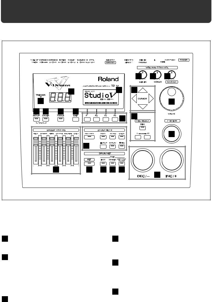
1 |
Trigger Indicator |
5 |
EXIT Button |
This will light when a trigger signal (signal produced when pad is struck) is received from a pad. It allows you to check whether the pad has been connected correctly.
Press this button and you will return to the screen one level higher in the hierarchy. Repeated pressing takes you back to the “DRUM KIT” page.
2 LED Display
Displays the number of the currently selected drum kit.
3 Graphic Display
During performance, this indicates the drum kit name and other important information. During editing, various graphics and text relative to the editing process is indicated.
*In this owner’s manual, this will be referred to simply as “the display.”
4 F1-F4 Buttons
These buttons change their function depending on the contents of the display. The lower part of the display will indicate the function of each button (p. 18).
6 TOOLS Button
Provides access to functions such as Copy, Undo, and Help. (p. 42, 117)
7 CHAIN Button
Lets you make Drum Kit Chain settings (a function that arranges drum kits in a desired order for successive selection) (p. 70, 116).
8 SETUP Button
Here you can make settings that affect the entire TD-10, such as trigger parameters and MIDI settings (p. 108).
14

Front and rear panel
9 GROUP FADERS
These allow you to adjust the volume of the kick, snare, hihat, other percussion instruments, backing instruments, and the click sound (p. 37).
10 SEQUENCER
Here are the buttons that control sequencer functions (playback/recording of performance patterns) (p. 68, 97).
11 KIT Button
Provides access to the basic display page used when playing the TD-10.
12 INST (Instrument) Button
Provides access to the display page in which you can edit instruments (p. 55, 80).
13 STUDIO Button
Provides access to the display page where you can choose mike types, their positions, ambience types and ambient mike positions (p. 62, 87).
14 CONTROL ROOM Button
Allows you to edit mixer, EQ, compressor and effect parameters (p. 65, 90).
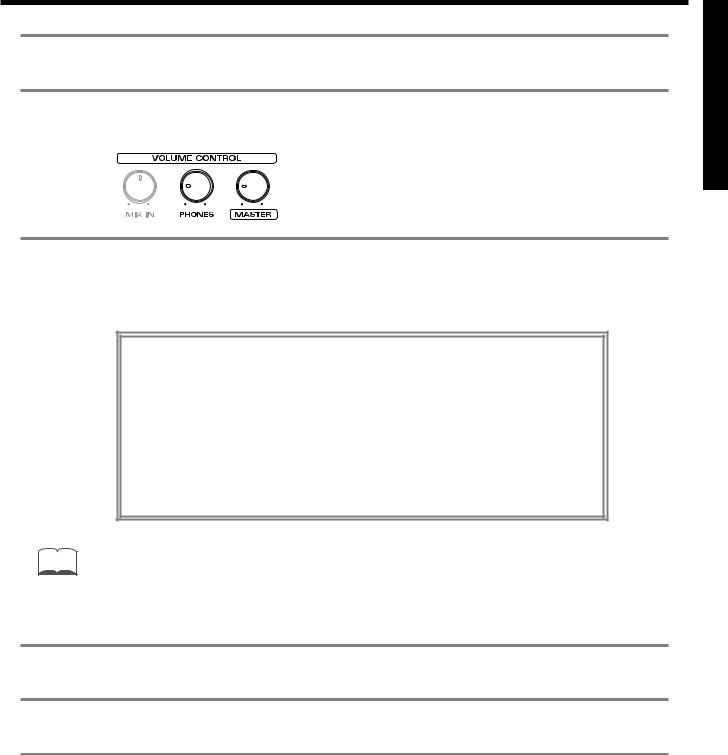
15 MIX IN Knob
This adjusts the volume of the device connected to the MIX IN jack. The sound from the MIX IN will be output from the MASTER out and/or the PHONES jack.
16 PHONES Knob
Adjusts the headphone volume. Even when headphones are connected, sound will still be output from the various output jacks.
17 MASTER Knob
Adjusts the volume of the MASTER OUT jacks. The volume of the PHONES jack is adjusted by the PHONES knob.
18 CURSOR Buttons
Used to move the cursor in the display, or to access the next display page (p. 18).
19 VALUE Dial
This dial has the same function as the INC and DEC buttons. Use this dial when you wish to make large changes in drum kit settings or edited values (p. 19).
20 TRIG SELECT
Use the lower two buttons to select the pad (trigger number) for which you wish to make settings. To select the rim of a pad, press the RIM button, then the RIM indicator is lit. If pads are connected to the TD-10, you can also select a pad by striking it. The PREVIEW button lets you audition the instrument that is assigned to the selected pad or the sound appearing in the display when editing a percussion group (p. 20).
21 PREVIEW Button
Used to audition an instrument. By using TRIG SELECT buttons to select a pad, you can play and edit sound even if no pads are connected to the TD-10. The button is velocity sensitive (p. 20).
22 INC Button, DEC Button
These buttons are used to switch drum kits or to modify values. Pressing the INC button increases the value, and pressing the DEC button decreases it. Since these buttons are large, you can also use the tip of your drum stick to press them (p. 19).
*Please be aware that hitting the buttons with a stick can cause malfunctions.
15
Front and rear panel
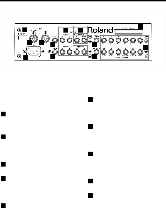
Rear Panel
33 |
|
|
28 |
23 |
|
|
27 |
||
32 |
31 |
29 |
|
25 |
|
|
|
||
|
|
|
|
24 |
34 |
|
30 |
|
26 |
23 |
MEMORY CARD Slot |
29 |
PHONES Jack |
An M-512E memory card (optional) can be inserted into this slot. Each memory card can store all settings of the TD-10, such as drum kits and sequencer performance data, etc (p. 114).
*The M-512E is the only memory card that can be used by the TD-10.
24 TRIGGER INPUT Jacks
Accept the pads or kick trigger units you want to connect to the TD-10. To connect a dual trigger type pad (PD-7, PD-9, PD-120), use a stereo cable (p. 24).
25 FOOT SWITCH Jack
Accepts connection of an optional foot switch (FS-5U). A foot switch can be used to select kits and start/stop the sequencer, etc. Use a special PCS-31 cable (optional) (p. 72, 120).
26 HH CTRL Jack
Accepts connection of a hi-hat control pedal (FD-7) (p. 36).
A pair of stereo headphones can be connected to this jack. Even if headphones are connected, sound will still be output from the OUTPUT jacks (p. 23).
30 MIX IN Jack
This jack is used to connect a CD or cassette player, or as a custom monitoring input for live/recording performances. The sound that is input to this jack will be output from the MASTER out jacks and/or the PHONES jack (p. 108).
31 MIDI IN Connector
Use this connector when you wish to use an external MIDI sequencer to play the sounds of the TD-10, or when loading TD-10 settings (bulk data) that were saved on an external device (p. 121).
32 MIDI OUT/THRU Connector
Use this connector when you wish to use play sounds in an external MIDI sound module/sampler from the pads, or when you wish to transmit TD-10 settings (bulk data) to another MIDI device (p. 121).
27 OUTPUT (MASTER) Jacks
These jacks output the instrumental sounds of the TD-10, and are for connection to external audio devices or amps. If you are listening in mono, connect to only the MASTER L (MONO) jack (p. 23).
28 OUTPUT (DIRECT 1, 2, 3) Jacks
The direct outs allow you to have more “separation,” over the total kit, and can be used for external effects etc. Ambience may also be sent from these outputs, but NOT the digital effects. Output assignments DIRECT 1, 2 or 3 jacks are found in the Control Room (p. 91).
33 POWER Switch
This switch turns the power on/off (p. 26).
34 AC Inlet
Connect the included AC power cable to this inlet (p. 23).
16

Important notes |
In addition to the items listed under “IMPORTANT SAFETY INSTRUCTIONS” and |
|
|
|
“USING THE UNIT SAFELY” on pages 2–4, please read and observe the following: |
Power Supply
●Do not use this unit on the same power circuit with any device that will generate line noise (such as an electric motor or variable lighting system).
●Before connecting this unit to other devices, turn off the power to all units. This will help prevent malfunctions and/or damage to speakers or other devices.
Placement
●Using the unit near power amplifiers (or other equipment containing large power transformers) may induce hum. To alleviate the problem, change the orientation of this unit; or move it farther away from the source of interference.
●This device may interfere with radio and television reception. Do not use this device in the vicinity of such receivers.
●Do not expose the unit to direct sunlight, place it near devices that radiate heat, leave it inside an enclosed vehicle, or otherwise subject it to temperature extremes. Excessive heat can deform or discolor the unit.
Maintenance
●For everyday cleaning wipe the unit with a soft, dry cloth or one that has been slightly dampened with water. To remove stubborn dirt, use a cloth impregnated with a mild, non-abrasive detergent. Afterwards, be sure to wipe the unit thoroughly with a soft, dry cloth.
●Never use benzene, thinners, alcohol or solvents of any kind, to avoid the possibility of discoloration and/or deformation.
Repairs and Data
●Please be aware that all data contained in the unit’s memory may be lost when the unit is sent for repairs. Important data should always be backed up on a RAM card/DATA card, in another MIDI device (e.g., a sequencer), or written down on paper (when possible). During repairs, due care is taken to avoid the loss of data. However, in certain cases (such as when circuitry related to memory itself is out of order), we regret that it may not be possible to restore the data, and Roland assumes no liability concerning such loss of data.
Memory Backup
●This unit contains a battery which powers the unit’s memory circuits while the main power is off. When this battery becomes weak, the message shown below will appear in the display. Once you see this message, have the battery replaced with a fresh one as soon as possible to avoid the loss of all data in memory. To have the battery replaced, consult with your dealer, or qualified Roland service personnel.
“Backup Battery Low !”
Additional Precautions
●Please be aware that the contents of memory can be irretrievably lost as a result of a malfunction, or the improper operation of the unit. To protect yourself against the risk of loosing important data, we recommend that you periodically save a backup copy of important data you have stored in the unit’s memory on a RAM card/DATA card, in another MIDI device (e.g., a sequencer).
●Unfortunately, it may be impossible to restore the contents of data that was stored on a RAM card/DATA card, in another MIDI device (e.g., a sequencer), in the unit’s memory once it has been lost. Roland Corporation assumes no liability concerning such loss of data.
●Use a reasonable amount of care when using the unit’s
buttons, sliders, or other controls; and when using its jacks and connectors. Rough handling can lead to malfunctions.
●Never strike or apply strong pressure to the display.
●When connecting / disconnecting all cables, grasp the connector itself—never pull on the cable. This way you will avoid causing shorts, or damage to the cable’s internal elements.
●A small amount of heat will radiate from the unit during normal operation.
●To avoid disturbing your neighbors, try to keep the unit’s volume at reasonable levels. You may prefer to use headphones, so you do not need to be concerned about those around you (especially when it is late at night).
●Since sound vibrations can be transmitted through floors and walls to a greater degree than expected, take care not to allow such sound to become a nuisance to neighbors, especially at night and when using headphones. Although the drum pads and pedals are designed so there is a minimal amount of extraneous sound produced when they're struck, rubber heads tend to produce louder sounds compared to mesh heads. You can effectively reduce much of the unwanted sound from the pads by switching to mesh heads.
●When you need to transport the unit, package it in the box (including padding) that it came in, if possible. Otherwise, you will need to use equivalent packaging materials.
●Use a cable from Roland to make the connection. If using some other make of connection cable, please note the following precautions.
Some connection cables contain resistors. Do not use cables that incorporate resistors for connecting to this unit. The use of such cables can cause the sound level to be extremely low, or impossible to hear. For information on cable specifications, contact the manufacturer of the cable.
Before Using Cards
Using DATA Cards
●New M-512E DATA cards do not yet have their battery installed. Before a DATA card can be used, you first need to insert the battery (refer to the instructions supplied with the DATA card).
●M-512E DATA cards are equipped with a PROTECT switch, which when turned on protects your data from accidental erasure. It is recommended that the switch be kept at the ON position, and switched to OFF only at the times you wish to write new data onto the card.
On Off
●When the battery in an M-512E DATA card is nearly worn out, the message below will be shown in the display. Refer to the instructions supplied with the DATA card and promptly replace the battery to avoid the loss of the data on it.
“MEMORY CARD Battery Low ! Please Change !”
●Carefully insert the DATA card all the way in—until it is firmly in place.
●Never touch the terminals of the DATA card. Also, avoid getting the terminals dirty.
17
About button operations and the screen displays
Operations common to all aspects of operating the TD-10 are covered below.
■ Saving your settings
For operations within the TD-10, there is no procedure for “saving settings.” When you modify the value of a setting, the new value is automatically saved as soon as you make the change.
■ Buttons, sliders and knobs
Buttons, sliders and knobs on the front panel will be printed in square brackets [ ]; e.g., [SETUP].
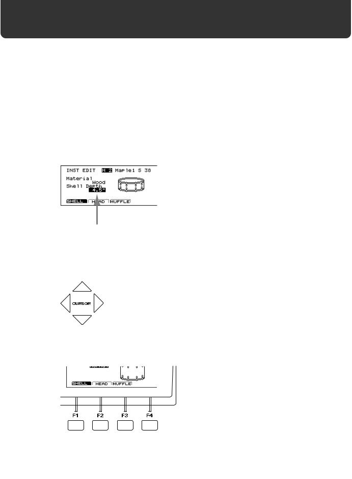
■ Cursor
fig.00-003e
Cursor
Cursor refers to the highlighted characters indicating an on-screen item that can be set. If the screen contains more than one item that can be set, use the [CURSOR] buttons to move it to the item that
you wish to set.
fig.00-003a
■ Function buttons ([F1]–[F4])
fig.00-004
The [F1]–[F4] buttons are called the “function buttons.” The bottom part of the display will show the names of the functions available for [F1]–[F4]. For example, if this owner’s manual makes reference to [INST]-[F1 (SHELL)], press [INST] , and then press [F1] (in this case, “SHELL” is displayed above [F1]).
18
About button operations and the screen displays
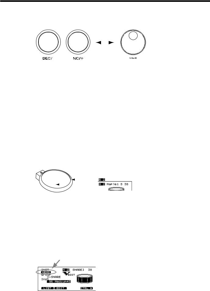
■ How to modify settings
fig.00-005e
INC/DEC button |
|
VALUE dial |
||||
|
|
|
|
|
|
|
|
|
|
|
|
|
|
|
|
|
|
|
|
|
[INC] and [DEC] (referred to in this manual as [INC/DEC]) and the VALUE dial are both used to modify the values of settings. The two methods have the following advantages.
[INC/DEC]
•Each time [INC] is pressed, the value increases. Each time [DEC] is pressed, the value decreases. This is convenient for fine adjustments.
•When making an on/off setting, [INC] will turn the setting on and [DEC] will turn it off.
•If you hold down [INC] and press [DEC], the value will increase rapidly. If you hold down [DEC] and press [INC] the value will decrease rapidly.
VALUE dial
Since the dial allows you to make major changes to the value at once, it’s a convenient way to make broad adjustments to a parameter quickly.
■ About the upper right of the screen display
fig.00-006e
|
|
Trigger number |
|||
|
|
|
Instrument name (or Trigger name) |
||
|
|
|
|||
|
Rim |
|
|
MIDI note number |
|
|
|
|
|||
|
|||||
|
|
|
|
|
|
|
|
|
|
|
|
|
|
|
|
|
|
|
Head |
|
|
|
|
In pages that allow you to make settings for each pad, you can strike the desired pad to see the setting page for that pad. At this time, the upper right of the display will show the number of the trigger jack to which the selected pad is connected, the instrument that it is using, and the MIDI note number. The first character (“H” or “R”) indicates whether the head or the rim of the pad is selected. The numerals at the right are the MIDI note number. You will need to know the MIDI note number when using the TD-10 as a MIDI sound module.
The “H” or “R” display will indicate whether the head or rim will sound when you press the Preview button. In cases where settings for the head and rim can be edited separately, the following
characters will also be displayed, letting you know the page in which you are.
fig.00-007
19
About button operations and the screen displays
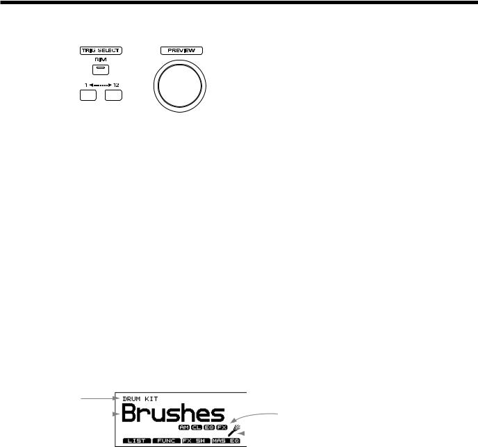
■ Selecting pads from the TD-10 front panel
fig.00-008
The trigger select buttons ([TRIG SELECT]) are used when you wish to select a sound for editing from the front panel of the TD-10, rather than by striking a pad as explained above. You can use these buttons to select a trigger number and edit the settings.
When you press the button marked “1,” the next lower-numbered trigger will be selected. When you press the button marked “12,” the next higher-numbered trigger will be selected.
When using a PD-7, PD-9 or PD-120, the rim button ([RIM]) lets you specify whether you are making settings for the head or the rim. When the [RIM] indicator is lit, the rim is selected.
By using these buttons in conjunction with the preview button, you can edit without pads connected to the TD-10.
*Depending on the instrument selection, there will be no distinction between head and rim in some cases. For details refer to p. 136.
■About the Preset Drum Kits
When the instrument is shipped from the factory, drum kits 1–50 are already pre-loaded. Even if you modify the settings of these drum kits, you can restore them to their factory settings at any time. These drum kits are referred to as the Preset Drum Kits. For details, refer to p. 137.
■ About the basic screen
fig.00-008ae
Screen name
|
|
Effect on/off |
|
Drum kit |
|
Settings for brushes |
|
name |
|
||
|
|
|
|
This screen is the TD-10’s basic screen, which will appear when you press [KIT].
In addition to the kit name, it displays the status of the memory card (p. 78), the effect on/off setting (p. 79), and whether or not the kit is for brushes (p. 79) etc.
20
Quick Start
Quick Start
21
Before you begin playing
This section explains the connections and settings that you must make before playing. The explanations here are given, assuming that the TD-10 has its factory settings.
MEMO |
The TD-10 provides a function for restoring the factory settings. Refer to “Restoring the factory settings (INI- |
|
TIALIZE)” on p. 137. |
||
|
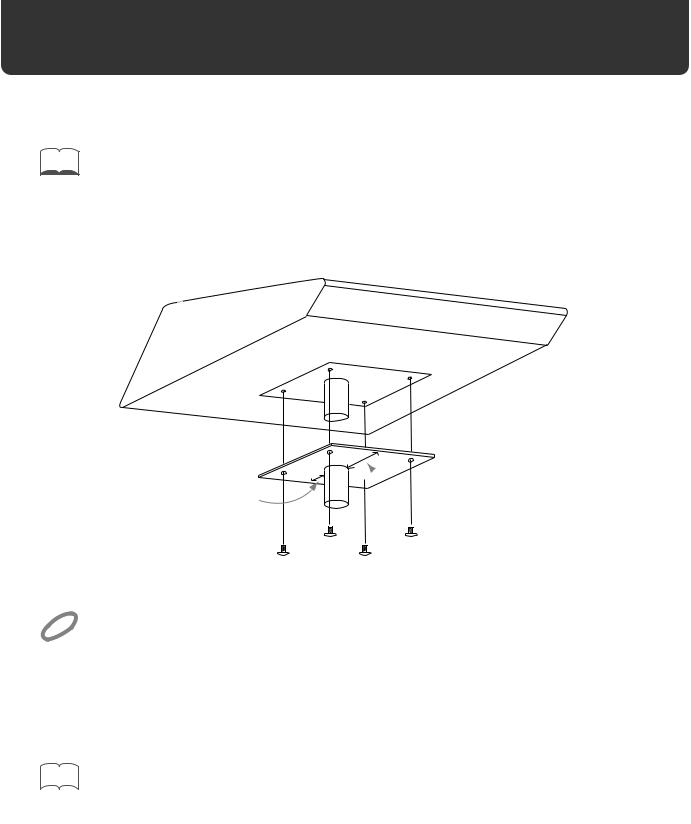
Mounting the TD-10 to the stand
Attach the stand holder (included with the optional MDS-7U/10) to the TD-10.
fig.00-009e

 Wide
Wide
Narrow
NOTE
Using the included screws, attach it so that the unit is oriented as shown in the above diagram.
Use the included screws. Using other screws can cause damage.
Next, attach the TD-10 to the drum stand (MDS-7U/10).
For details on assembling the drum stand and attaching the TD-10, refer to the owner’s manual for the drum stand (MDS-7U/10).
|
|
|
To attach the TD-10 to a cymbal stand (or the like), you may want to make use of the separately available |
|
MEMO |
|
|
|
|
APC-33 All Purpose Clamp. |
|
|
|
|
Make sure, though, that the cymbal stand you intend to use has pipes with a diameter of between 10.5 and 30 |
|
|
|
millimeters. |
22
Before you begin playing
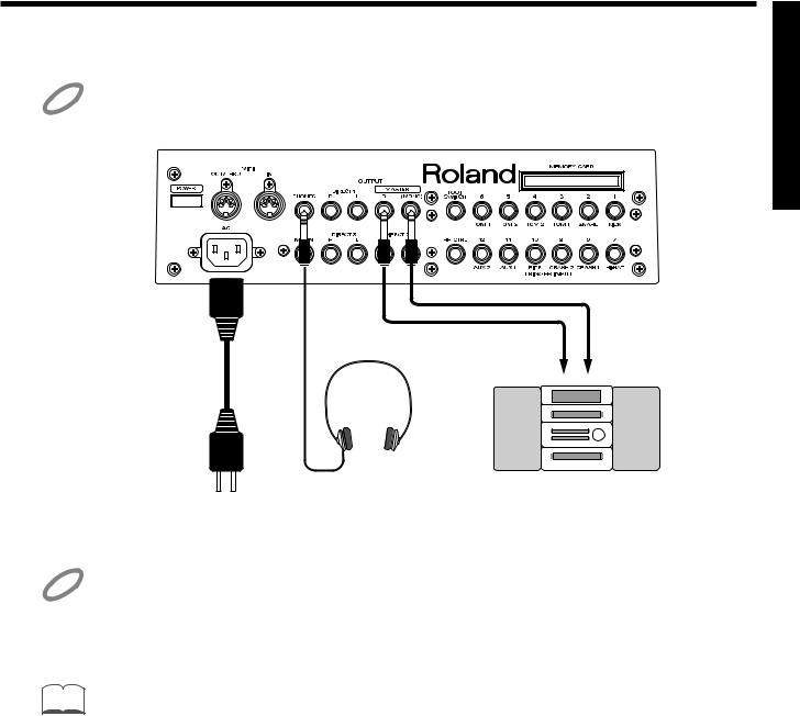
Connect your audio system or amp
NOTE
fig.00-010e
NOTE
MEMO
To prevent malfunction and/or damage to speakers or other devices, always turn down the volume, and turn off the power on all devices before making any connections.
|
Audio cable |
|
Power cord |
R |
L |
to AC |
|
|
power outlet |
Stereo headphones |
Audio set, etc. |
Connect the rear panel MASTER L(MONO) and R jacks to your audio system or amps. If you will be using headphones, connect them to the PHONES jack.
Be sure that the TD-10’s MASTER L and R jacks are connected respectively to the L and R of your audio system or amps.
In consideration of live performance situations, the headphone output is designed to produce a higher volume than other electronic musical instruments. Extended listening at high volumes will damage your hearing, so please pay attention to the volume adjustment.
At the factory settings, no sound will be output from the DIRECT 1, DIRECT 2 or DIRECT 3 jacks.
Quick Start
23

Before you begin playing
Connecting pads and pedals
Using the cables provided, connect your pads, hi-hat control pedals and kick trigger units as shown in the above diagram. Special jacks are provided for the kick (KICK) and snare (SNARE), so make
the correct connections to these jacks.
fig.00-011e
TD-10 Rear panel
Roland
Roland
24
Before you begin playing
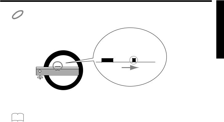
If you are using a PD-7 or PD-9, move the polarity switch located on the back of the pad to the “-(Roland)” NOTE position. When using a KD-7, either position will do.
fig.00-012
OUTPUT POLARITY
+ - (Roland)
PD-7, PD-9
|
|
|
To have the most expressive performance, we recommend the use of the Roland pads (PD-5, PD-7, PD-9, PD- |
|
MEMO |
|
|
|
|
100, PD-120) and kick trigger units (KD-7). |
Quick Start
25
Before you begin playing
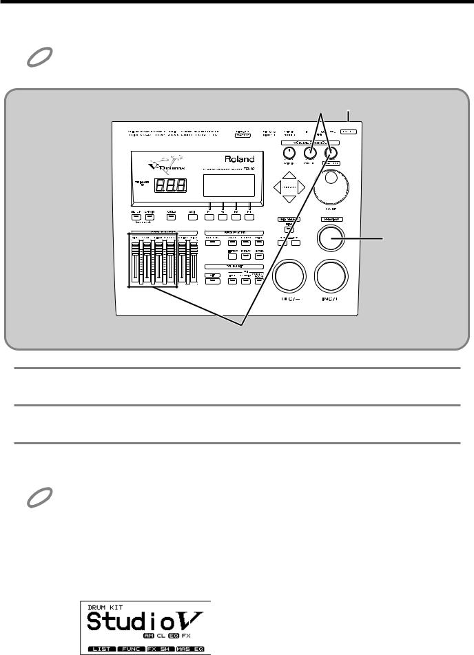
Turning on the power
Once the connections have been completed (p. 23, 24), turn on power to your various devices in the order spec- NOTE ified. By turning on devices in the wrong order, you risk causing malfunction and/or damage to speakers and
other devices.
fig.00-013
1 3
6
5
1 Rotate [MASTER] and [PHONES] all the way to the left to turn down the volume.
2 Turn down the volume of the connected amp or audio system.
3 Turn on the POWER switch located on the rear panel of the TD-10.
NOTE Caution when turning on the power
●After turning on the power, do not press the hi-hat control pedal (FD-7) until the drum kit name (see the following illustration) appears in the display.
If the pedal was pressed while the power was being turned on, hi-hat open/close operations cannot be performed correctly.
●After turning on the power, do not strike a pad until the drum kit name appears in the display.
Striking a pad while the power is being turned on will cause poor response when the pad is struck softly.
fig.00-037
26
Before you begin playing
4 Turn on the power of the connected amp or audio system.
5 Raise the [GROUP FADERS] sliders to the maximum position, and adjust [MASTER] ([PHONES])
to the position shown in the diagram.
fig.00-014a
Quick Start
6 While striking [PREVIEW] with your finger, adjust the volume of the connected amp or audio system. If you are using headphones, gradually raise [PHONES] to adjust the volume.
The TD-10 will produce sound. The volume will depend on the force with which you struck [PREVIEW].
If there is no sound when you strike [PREVIEW] ...
Check the following points.
·If you are using headphones, are they connected to the PHONES jack?
·If you are using an external amp, is it connected to the MASTER jacks? Are the audio cables connected correctly to the input jacks of the external amp, etc.?
·Could there be a problem with the cables connected to the external amp?
·Are the input select settings of the external amp correct?
·Are the [GROUP FADERS] sliders lowered?
·Could the [PHONES] volume be too low?
·Could the [MASTER] volume be too low?
MEMO |
You can use [TRIG SELECT] to select and audition the instrument for each pad. |
|
■ To turn the power off ...
1 Make sure that the TD-10 volume controls and the connected external devices are turned to the minimum position.
2 Turn off the power of the external devices.
3 Turn off the power of the TD-10.
27
Before you begin playing
Listening to the internal demo playback
The TD-10 contains demo songs that demonstrate its sounds and expressive capabilities. The demo song is a “rainbow” of 4 short songs, arranged as a medley. It plays back in “loop” (repeating)
mode, yet you can also listen, starting from any of 4 positions, accessed as follows:
fig.00-015
2
3
1 5 4
1 Set each of the [GROUP FADERS] sliders [KICK][SNARE][HI-HAT][OTHERS][BACKING] to the same volume.
2 Hold down [SETUP] and press [CHAIN].
In this display, the cursor defaults to “Rock.”
3 Use [INC/DEC] or the VALUE dial to select the “section” number.
You can start listening from the beginning of any of the four sections.
4 Press [PLAY].
You can listen to the medley and it will continue to loop.
During playback, the [GROUP FADERS] function normally allowing you to mix the demo song as you wish. (for more info on the [GROUP FADERS], see page 37.)
5 Press [STOP] to stop playback.
Once you are through listening to the demos, press [EXIT] to return to the “DRUM KIT” page.
NOTE
MEMO
All rights reserved. Unauthorized use of this material for purposes other than private, personal enjoyment is a violation of applicable laws.
No data for the music that is played will be output from MIDI OUT/THRU.
Drum kit 39–42 are used in the Demo Song.
For details of the Demo Song, refer to page 179.
28
Before you begin playing
Specify the pads that the TD-10 will use
In order for the TD-10 to accurately receive trigger signals from each pad, you must specify the type of pad that is connected to each TRIGGER INPUT jack.
■ If you have purchased the “V-Basic Kit” or “V-Standard Kit”
Trigger settings for the V-Basic Kit or the V-Standard Kit are provided, so you can call up and select
them.
fig.00-016
1 |
2 |
3
Quick Start
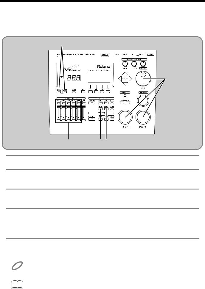
1 Press [SETUP], press [F1 (TRIG)], and then press [F1 (BANK)].
2 Use [CURSOR] to move the cursor to the “BANK” number.
3 Use [INC/DEC] or the VALUE dial to make the setting.
V-Basic Kit: BANK 1 V-Standard Kit: BANK 2
NOTE
If the settings have been modified and are different than the settings in the above diagram, use the Copy function to restore the factory settings (p. 137).
This completes settings for all pads of the V-Basic Kit or V-Standard Kit. If you are using a PD-100 or PD-120, make settings for the head tension as explained on p. 31.
Once you have completed your settings, press [EXIT] enough times to get back to the “DRUM KIT” page.
29
Before you begin playing
■ If you have purchased the PD-5, PD-7, PD-9, PD-100 or PD-120 individually
Make the following settings for each pad.
fig.00-023
1 |
2 |
4
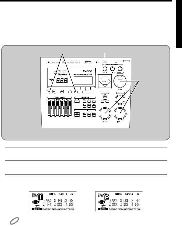
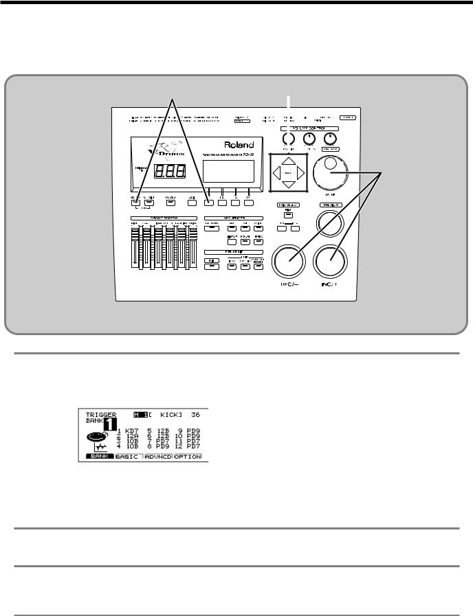
1 Press [SETUP], press [F1 (TRIG)], and then press [F1 (BANK)].
The following screen will appear:
fig.00-017
This screen shows a list of pad models that are specified for each TRIGGER INPUT jack.
Display |
Pad name |
PD5 |
PD-5 |
PD7 |
PD-7 |
PD9 |
PD-9 |
10A |
PD-100 |
12A |
PD-120 |
KD7 |
KD-7/KD-5 |
* For details on 10B and 12B, refer to p. 108.
2 Use [CURSOR] to move the cursor to a location other than “BANK.”
3 Strike the pad for which you wish to make settings.
The cursor will move to the edited value of the pad that you struck.
4 Use [INC/DEC] or the VALUE dial to select the model name of the pad.
This completes pad settings. If you are using a PD-100 or PD-120, make settings for the head tension as explained in the following section.
30
 Loading...