


SYSTEM-100
Table of contents
 Loading...
PLUG-OUT Software SynthesizerSYSTEM-100
Owner’s Manual
Copyright © 2015 ROLAND CORPORATION
All rights reserved. No part of this publication may be reproduced in any form without the written permission of ROLAND CORPORATION.
01

Introduction
When you use the SYSTEM-100 for the rst time, you must specify the MIDI Input/Output in the
Setting window (p. 12).
For details on the settings for the DAW software that you’re using, refer to the DAW’s help or
manuals.
The SYSTEM-1 and SYSTEM-1m are described as SYSTEM-1 in this manual.
About this product
• In the interest of product improvement, the specications and/or contents of this package are subject to change without
prior notice.
• The explanations in this manual include illustrations that depict what should typically be shown by the display. Note,
however, that your unit may incorporate a newer, enhanced version of the system (e.g., includes newer sounds), so what you
actually see in the display may not always match what appears in the manual.
About Trademarks
• VST is a trademark and software of Steinberg Media Technologies GmbH.
• The Audio Units logo is a trademark of Apple Inc.
• Roland and PLUG-OUT are either registered trademarks or trademarks of Roland Corporation in the United States and/or
other countries.
• Company names and product names appearing in this document are registered trademarks or trademarks of their
respective owners.

Screen Structure
Patch Memory name
This area shows the name of the
selected patch memory.
[PATCH] button
Selects a patch memory.
The Patch Select window opens.
p. 8
Sound section
This area shows modules such
as LFO and VCO. For details on
corresponding controllers when
you plug-out, refer to “Module List.”
p. 14
[SIGNAL FLOW] button
Shows the signal ow.
[HIDE CABLES] button
Turns o cable operations, allowing
you to operate knobs or sliders that
were hidden under cables.
[SEND] button
Sends the memory to the
SYSTEM-1.
* These work only when the SYSTEM-1 is in PLUG-OUT (SYSTEM-100) mode.
p. 11
[GET] button
Loads the memory currently
being edited in the SYSTEM-1’s
PLUG-OUT mode (temporary)
into the SYSTEM-100.
p. 11
[PLUG-OUT] button
Plug-outs the SYSTEM-100.
Level meter
Displays output levels of the SYSTEM-100.
[TUNE] knob
Adjusts the overall pitch of the
SYSTEM-100.
[OPTION] button
Here you can choose skins and
use MIDI Control Mapping.
These settings can be made
separately for each instance of the
SYSTEM-100.
p. 12
[SETTING] button
Here you can edit the MIDI
settings and the direction of
mouse wheel scrolling (Only Mac).
These settings are shared by all
instances of the SYSTEM-100 that
you are using.
p. 12
[ABOUT] button
Here you can view information
about the SYSTEM-100.
[HELP] button
Displays help.
ROUTING MATRIX
In this matrix, the output jacks of
each module are placed in vertical
columns, and the input jacks are
placed in horizontal rows. Click
an intersection to change the
corresponding connection.
[VOLUME] knob
Adjusts the overall volume of the
SYSTEM-100.
[KEYBOARD] button
Toggles the keyboard area between
visible and hidden.
[BEND RANGE] knob
Species the amount of pitch
change that occurs when pitch
bend messages are received.
[TEMPO SYNC] button
Press this to make it light if you
want to synchronize to the tempo
of your host application (DAW).
Synchronization tempo range:
40–300
Keyboard
Click here to produce sound.
When a MIDI message is received,
the corresponding key responds.
[KEY ASGN] switch
Species how the assigner
operates.
1 Lowest key has priority.
2 Later key has priority.
3
ARPEGGIO section
Here you can make arpeggio settings.
ARPEGGIO
ARP TYPE
ARP STEP
If this is lit, an arpeggio
plays.
Selects the arpeggio
variation.
Selects the speed of the
arpeggio.
SCATTER section
Here you can make settings for the
Scatter eect on arpeggio performance.
To use Scatter, make the [ARPEGGIO]
button light.
SCATTER
TYPE
SCATTER
DEPTH
KEY HOLD
OCTAVE
Selects a type of scatter.
Adjusts the amount of
scatter.
If this is lit, you can make
notes continue sounding
even after you take your
hand o the keyboard.
You can shift the
keyboard’s pitch range in
steps of one octave.
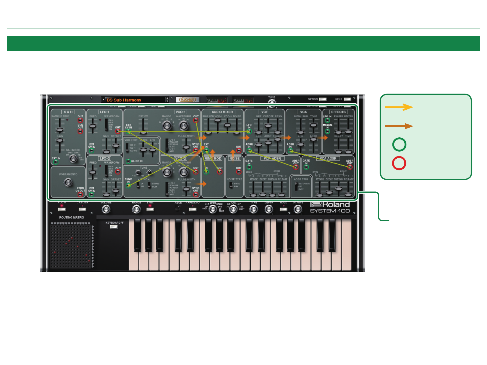
Modules and the Overlay Display
SYSTEM-100 has an overlay display function that lets you see how modules without cable connections are internally connected. The overlay display shows internal connections as yellow arrows.
To display the overlay, press the [SIGNAL FLOW] button.
Internal connection
Audio signal
Input jack
Output jack
Screen Structure
Overlay display
4

SYSTEM-100 Input/Output Jacks and SYSTEM-1m Jack Area
SYSTEM-100 modules provide input/output jacks. You can create sounds by using these jacks to connect modules to each other.
Some of the input/output jacks are linked with the jack area of the SYSTEM-1m, allowing you to control SYSTEM-100 using CV/GATE input from an external device.
NOTE
If a patch cable is connected to an input jack of the SYSTEM-1m, the input signal to the SYSTEM-1m takes priority and the input signal to the corresponding SYSTEM-100 input jack is ignored.
SYSTEM-1m
Screen Structure
SYSTEM-100
5

Making Connections and Editing Parameters
Be aware of the following points when connecting modules.
NOTE
5 Output jacks can be connected to input jacks. You cannot connect an input jack to another
input jack, nor an output jack to another output jack.
5 You can connect cables from one output jack to multiple dierent input jacks.
5 One cable can be connected to an input jack.
5 If a patch cable is connected to an input jack of the SYSTEM-1m, the input signal to
the SYSTEM-1m takes priority, and the input signal to the corresponding input jack of
SYSTEM-100 is ignored.
Input signal priority order
SYSTEM-1m input jack > SYSTEM-100 input jack > SYSTEM-100 internal connection
Connecting a Cable
1. Move the cursor to the input or output jack that
you want to connect, and drag.
2. Drop the end of the cable on the desired output or
input jack.
Drag
Disconnecting
1. Move the cursor to the input/output jack or to the middle of the cable that you
2. Drop the end of the cable where there is
want to disconnect, and drag.
The cable color changes to highlighted.
* If multiple cables are connected from an
output jack, you can click the jack to select a
dierent cable.
no jack.
The connection is broken and the cable
disappears.
* If the jack has an internal connection, it returns to the default state when you disconnect
the cable.
* In the
“ROUTING MATRIX” (p. 7), multiple connections can be disconnected or returned to
their default state by holding down the [Shift] key and dragging to enclose an area of the
red shorting pins.
Drag
Drop where
there is no jack
Changing a Connection
1. Move the cursor to the input/output jack or to
the middle of the cable whose connection you
want to change, and drag.
The cable color changes to highlighted.
* If multiple cables are connected from an output jack,
you can click the jack to select a dierent cable.
2. Drop the end of the cable on the desired output/
input jack.
Drag
6
Making Connections and Editing Parameters
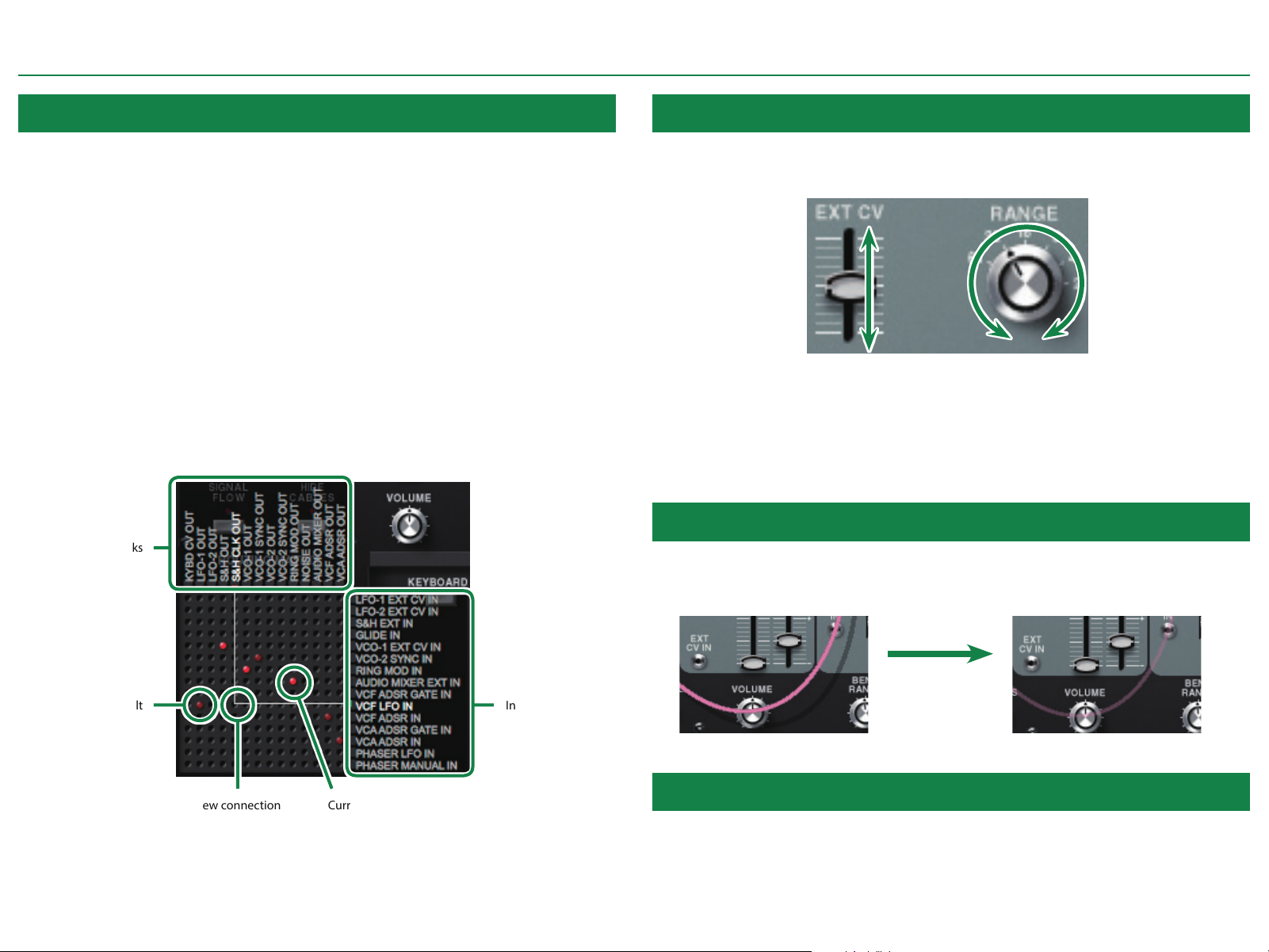
ROUTING MATRIX
SYSTEM-100 lets you make connections by using the ROUTING MATRIX, which works like a
routing switcher.
In the ROUTING MATRIX, the output jacks of the modules are assigned to the vertical columns,
and the input jacks are assigned to the horizontal rows. You can make a connection by clicking
an intersection. When a connection exists, a red shorting pin is shown.
If an input jack is already connected, and you click the intersection of that input jack with
a dierent output jack, the connection changes to the new connection (the last click takes
priority).
If you click a current connection (a red shorting pin), that connection is disconnected. This lets
you return the connection to its default state.
* If a jack has an internal connection, it returns to its default state (a dim red shorting pin)
when disconnected.
* By holding down the [Shift] key and dragging to enclose multiple shorting pins, you can
disconnect multiple connections or return them to their default state.
Output jacks
Operating Knobs or Sliders
To change the parameter value of a knob or slider, drag around the perimeter of the knob or
drag the slider up or down. When you drag, the value is shown below the knob or slider.
KnobSlider
* If you hold down the [SHIFT] key of your computer while you drag, or if you drag at a
distance from the controller, the value changes in smaller amounts, allowing you to make
ne adjustments.
* If you click the controller while holding down the [Command (CTRL)] key of your computer,
it returns to its default state.
Turning Cable Operation On/O
When you make a connection, the cable may overlap a knob or slider. If you want to operate
that knob or slider, turn o cable operation by making the [HIDE CABLES] button light. The
cable color turns semi-transparent.
Default
Input jacks
[HIDE CABLES] button On (lit)[HIDE CABLES] button O (unlit)
Current connectionNew connection
Changing the Cable Color
You can change the cable color to your taste. To change the cable color, double-click the
middle of a cable.
7
Loading...