


QUICK START
Thank you, and congratulations on your choice of the Roland VM-C7200 (VM-C7100) V-Mixing Console.
The documentation for the VM-7000 Series consists of the volumes as listed below.If you are using the VM-7000 for the first time, we recommend you to first start with the “Quick Start” (this volume) when using this system, to get a thorough grasp of its operation performance ability. The details to the use for every function can be found in the Console (C7200/C7100) section of the “Owner’s Manual”. Look up the function you are searching for on the index and read the chapter carefully.
For The Console
•Quick Start (this volume): Easy instructions for basic steps of operations.
•VM-C7200/C7100 Owner’s Manual: Detailed instructions for each function, glossary, Q&As, Parameter List, MIDI Implementation, etc.
•VM-C7200/C7100 Libraries: Internal connections templates, list of EQ and effects preset library
For The Processor
•VM-7200/7100 Owner’s Manual: Instructions for using the Processor, how to install optional devices, etc.
•VM-7000 SERIES Block Diagram: Block diagram of the whole system
* adat® |
is a registered trademark of ALESIS Corporation. |
*TASCAM® 

 is a registered trademark of TEAC Corporation.
*All product names mentioned in this document are trademarks or registered trademarks of their respective owners.
fig.0-03
Copyright © 1999 ROLAND CORPORATION
All rights reserved. No part of this publication may be reproduced in any form without the written permission of ROLAND CORPORATION.
Roland Website |
http://www.roland.co.jp/ |
Roland US Website |
http://www.rolandus.com/ |

Table of Contents |
|
Getting Started ........................................................................................ |
4 |
How to Use The QUICK START............................................................................................................... |
4 |
Installing the VM-C7100/C7200 Digital Mixing System....................................................................... |
5 |
Connections.................................................................................................................................................. |
7 |
Turning On the Power.............................................................................................................................. |
10 |
To Adjust the Brightness of the Display ................................................................................................ |
12 |
If You’re Confused About What’s Being Displayed or What’s Going On ....................................... |
12 |
Restoring the Original Factory Settings................................................................................................. |
13 |
Setting the Internal Clock......................................................................................................................... |
14 |
Preparing a Memory Card....................................................................................................................... |
16 |
To Format a Memory Card........................................................................................................... |
16 |
To Create a New Project ............................................................................................................... |
19 |
Turning Off the Power ............................................................................................................................. |
20 |
Before Mixing Operations .................................................................... |
22 |
Internal Signal Flow.................................................................................................................................. |
22 |
1. Input Channels........................................................................................................................... |
22 |
2. Busses / Output Routes............................................................................................................ |
23 |
How to Operate This System................................................................................................................... |
24 |
The Display (example) .................................................................................................................. |
24 |
To Change Parameters .................................................................................................................. |
25 |
Mixing Operations................................................................................. |
26 |
Setting the Input Gain .............................................................................................................................. |
26 |
Setting the Channel Levels and L/R Pans............................................................................................. |
28 |
Setting the Master Level and Master Stereo Balance ........................................................................... |
30 |
Adjusting a Signal’s Tone (Equalizer).................................................................................................... |
32 |
Setting Up a Monitor ................................................................................................................................ |
34 |
Coupling Adjacent Channels .................................................................................................................. |
36 |
Muting a Channel ..................................................................................................................................... |
38 |
Storing a Project......................................................................................................................................... |
39 |
Using Sub Outputs ............................................................................... |
40 |
Setting Up Monitor Sends for Studio or Stage...................................................................................... |
40 |
To Select Signals for Studio Monitors......................................................................................... |
40 |
To Talk to Someone on a Stage or out in a Studio (Talkback)................................................. |
42 |
Flex Bus....................................................................................................................................................... |
43 |
Flex Bus Output (MULTI OUT/ASSIGNABLE OUT) ............................................................. |
44 |
Flex Bus Output (Internal)............................................................................................................ |
46 |
Sending Signals to a Flex Bus .................................................................................................................. |
48 |
Using On-Board Effects ....................................................................... |
50 |
Send-Return Loop Effect .......................................................................................................................... |
51 |
Setting the Onboard Effect Position and Value .................................................................................... |
54 |
Selecting the Effects .................................................................................................................................. |
58 |
Using a Channel’s Feedback Delay (Channel Delay) .......................................................................... |
60 |
Other Important Features..................................................................... |
62 |
Storing a Mixing State (Scene)................................................................................................................. |
62 |
To Store a Scene ............................................................................................................................. |
62 |
To Recall a Scene............................................................................................................................ |
64 |
Setting Signal Routings on the Display (Virtual Patchbay) ................................................................ |
66 |
Simultaneously Adjusting the Levels of Multiple Channels .............................................................. |
68 |
To Create a Group of Channel Faders (Fader Group Master) ................................................ |
68 |
To Mute a Group of Multiple Channels (Mute Group) ........................................................... |
70 |
2

Table of Contents
Some Special Features......................................................................... |
72 |
The Spectrum Analyzer........................................................................................................................... |
72 |
5.1 Surround.............................................................................................................................................. |
73 |
Speaker Modeling..................................................................................................................................... |
74 |
Using EZ Routing Templates ............................................................... |
75 |
8 Track MDM With MIDI Sound Module Recording ......................................................................... |
76 |
Live Jazz Ensemble With 8 Track Digital Recording .......................................................................... |
82 |
Advanced Operations – 8 Track Analog Recording ................................................................ |
86 |
Connection Samples ............................................................................ |
88 |
Connection Samples Using the TASCAM DA Series.......................................................................... |
88 |
48 Track Recording System (TASCAM DA-88 x 6).................................................................. |
88 |
48 Track Recording System (TASCAM DA-88 x 6 + RC-848)................................................. |
89 |
24 Track Recording System (TASCAM DA-88 x 3).................................................................. |
90 |
8 Track Recording System (TASCAM DA-88 x 1).................................................................... |
91 |
Connection Samples Using the Alesis ADAT Series........................................................................... |
92 |
48 Track Recording System (Alesis ADAT x 6) ........................................................................ |
92 |
48 Track Recording System (Alesis ADAT x 6 and BRC)........................................................ |
93 |
24 Track Recording System (Alesis ADAT x 3) ........................................................................ |
94 |
48 Track Recording System (Alesis ADAT x 1) ........................................................................ |
95 |
Connection Sample Using Digidesign Protools................................................................................... |
96 |
3

Getting Started
How to Use The QUICK START
The QUICK START basically explains the operations as follows:
Mixing Operations
Now let’s do some mixing. This chapter describes two-channel – stereo – mixing of connected sources that will be sent out from the system through its MAIN OUT jacks.
Setting the Input Gain
Let’s adjust the input gain levels of all of your connected instruments and so on. (If you are working on digital connected sources, you do not have to read this section.)
|
fig.107 |
|
|
2 |
1 |
1 |
Press [PREAMP GAIN]. |
|
|
|
[PREAMP GAIN] lights and the “PREAMP GAIN” display appears.
fig.206
Owner’s Manual “Gain, Phantom Power Supply, Phase and Attenuator” (p.68)
As preset at the factory, all channel numbers on the console correspond to the input numbers on the processor. You may, however, change the channels’ connections or work on multiple channels at once (Owner’s Manual
“Selecting an input channel’s signal source” p.67).
If you selected DIGITAL IN A/B as your source input, these steps will not be necessary.
You can also set the gain level with the cursor and knobs on the display.
Important notifications to prevent considerable damage to your equipment.
Reference page for detailed information to this section.
Other convenient setup operations.
Additional suppllemental remarks.
Keys or knobs used in the corresponding Step number.
The display mainly used during the operation.
26
Step number in the setup procedure.
•For further information to operations or functions, read your console’s and processor’s Owner’s Manuals.
4

Getting Started
Installing the VM-C7100/C7200 Digital
Mixing System
The VM-C7100/C7200 Digital Mixing System consists of two units – the
mixing console and the mixing processor.
About the VM-C7100/C7200 Digital Mixing System
The Mixing Console
Owner’s Manual “Names
of Things and What They
Do” (p.11)
All mixing activities take place on the mixing console, including the adjusting of faders, the assignment of signals to busses and the application of effects.
Place the console in an area such as a control room. Then, connect your monitors, audio equipment, stereo mastering recorders and headphones to the corresponding jacks on the console.
You may attach an optional wooden panel and a level meter bridge (sold separately) to the console.
The Mixing Processor
OWNER’S MANUAL for the Processor
The mixing processor supplies the majority of the system’s input and output jacks.
Place the processor at a convenient location near your performers, such as in a studio or on a stage. Next, connect instruments, microphones, amplifiers, multi-track recorders, effects processors, and monitors for the performers to the corresponding mixing processor jacks.
Up to 2 processors can be connected to each console, which enables you to achieve 94 input channels (Owner’s Manual “Settings related to cascade connection” p.41, OWNER’S MANUAL for the Processor “Connecting Two Processors (Cascade Connection)” p.32 ).
5

Getting Started
To Connect the VM-C7100/C7200 Digital Mixing System
Use a pair of AES/EBU digital audio cables to connect the mixing console and mixing processor. These
cables are supplied as a set with the mixing console.
Use the supplied pair of
AES/EBU Digital Audio Cables.
6
Getting Started
Connections
To avoid problems and/or damage to speakers or other devices, always turn down the 
 volume and turn off the power on all devices before making any connections.
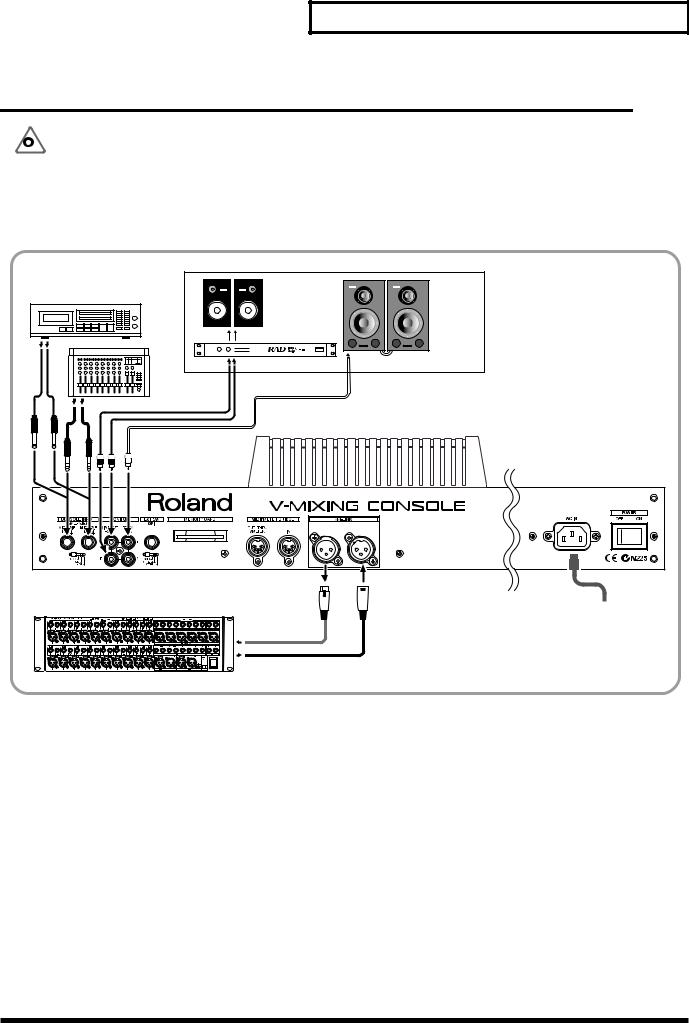
Basic Connections
Rear Panel of the Mixing Console
Microphone, Sub Mixer,
MD/CD Player
Monitor in the |
Digital |
|
Control Room |
||
Powered |
||
Speaker |
||
Speaker |
||
Amp |
(Roland DS-90 etc.) |
Mixing Processor
AC Power Supply
7

Getting Started
Front Panel of the Mixing Processor
Channel Insert (Effects Processor)
Monitor Speaker
Synthesizer,
Sound Module, etc
|
|
|
|
|
|
|
Branch Cable |
Monitor Amp, |
|
|
|
|
|
|
|
(e.g. PCS-31) |
Headphone Amp |
|
|
3 |
4 |
5 |
|
6 |
|
for Players |
1 |
2 |
3 |
4 |
|
|
|
|
|
|
|
|
|
|
|
|||
|
|
|
5 |
6 |
7 |
8 |
Digital |
|
|
|
|
Audio |
|
||||
|
|
|
|
|
|
|
Input/Output |
|
Microphone |
|
|
|
|
|
|
|
|
|
|
|
|
|
|
|
AES/EBU Jack |
|
|
|
|
|
|
|
|
on Pro Audio Device |
Mixing Console |
|
|
|
|
|
|
|
|
8
Getting Started
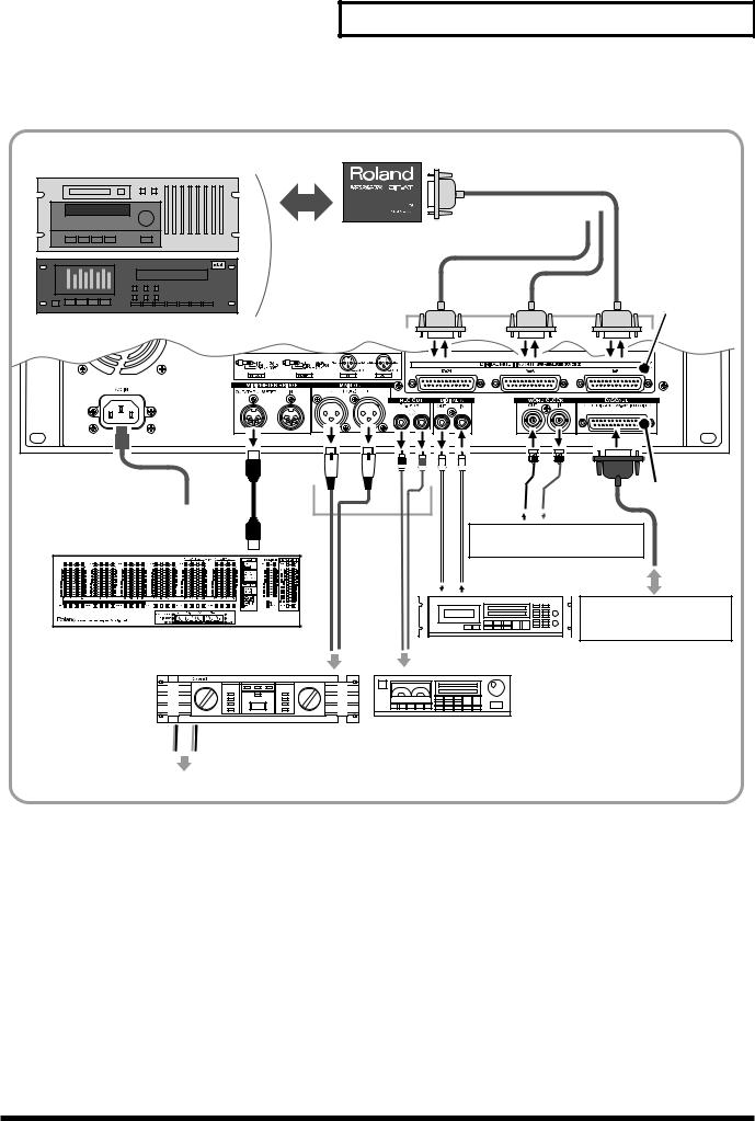
Rear Panel of the Mixing Processor
Digital Multi-track Tape Recorder
(TASCAM/ADAT)
8 ch
Roland DIF-AT
To R-BUS Compatible
(Interface Box)
Device
R-BUS
Cable VM-24E (Option)
|
Main |
VM-24C |
|
(Option) |
|
AC Power Supply |
Output |
|
|
Cable supplied |
|
|
Word Clock Connector on |
|
MB-24 (Option) |
with the |
|
Digital Recorder or similar device |
VM-24C |
|
|
Digital Input/Output |
|
|
Mixing Processor to be |
|
|
connected in cascade |
|
|
(VM-7200/7100) |
|
|
DAT/MD Recorder, etc. |
|
|
Analog Input |
|
Power Amp
Tape Recorder, MD Recorder, etc.
PA Speaker
If you wish to connect the VM-C7100/C7200 to ADAT or TASCAM digital multi-track tape recorders, you must first install an optional VM-24E, sold separately (OWNER’S MANUAL for the Processor “Installing R- BUS (RMDB2) Connectors (VM-24E)” p.14).
9
Getting Started
Turning On the Power
After you have finished making connections (QUICK START: p.7), be sure to turn on all of your devices in the proper order, as described in the instructions below. Powering up in the wrong order may cause malfunctions and/or damage to speakers and the devices.
Always make sure that each device’s volume level is turned down before turning on its power. You may hear a slight noise even with the volume turned down – this is normal, however, and does not indicate a malfunction.
1
2
3
Turn on the power of any connected digital multi-track tape recorder.
It takes a while for the device to startup.
Turn on the power of any additional connected digital devices (DAT, MD recorder, hard disc recorder, etc.).
Turn on the power of any connected analog devices (instruments, sound modules, effects processors, microphones, CD players, MD players, tape recorders, etc.).
If an external device is to be the source of the system’s Word Clock (Owner’s Manual: p.31), turn on the power of that device first.
10
4
5
6
7
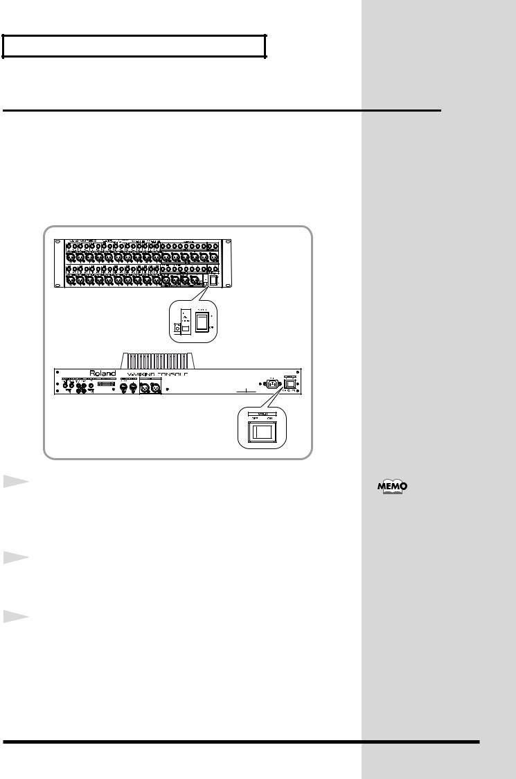
Getting Started
Set [POWER] to ON on the front panel of the mixing
processor.
The CTRL indicator blinks during startup. When startup is completed, the
indicator lights in green.
After the CTRL indicator on the processor has turned green, set [POWER] to ON on the rear panel of the mixing console.
When the “Check SYSTEM CONFIGURATION” message appears on the display, press [F2](START) to execute the startup procedure.
The “LEVEL METER” display appears.
It takes a short while for the system to start up. When you turn on the power, all connected external devices must be recognized by the system, and certain data must be loaded.
Turn on the power of connected audio equipment (amplifiers
and speakers).
When you change settings on a digital connected device, a loud noise may occur. Always turn down the volumes to all speaker outputs to prevent serious damage to your equipment, before working on your digital devices.
When connected in cascade (Owner’s Manual
“Settings related to cascade conection” p.41), turn on the power of the Slave processor (“2nd UNIT”) first.
11

Getting Started
To Adjust the Brightness of the Display
You may wish to adjust the brightness of the display immediately after power-up, under unusual viewing conditions, or after the unit has been on for an extended period of time. Adjust the brightness of the screen using the [CONTRAST] knob on the left bottom of the display.
If You’re Confused About What’s Being Displayed or What’s Going On
If you become confused about what you’re seeing on the display, or have lost your way during some procedure, press [LEVEL METER]. The display returns to the screen shown immediately after power-up. You can try the procedure you have been working on again from the beginning.
LEVEL METER
If you find that your system functions differently than described in the QUICK START or the Owner’s Manual, read “Troubleshooting” (Owner’s Manual: p.261) for further information.
If the above steps do not resolve your problem, contact a nearby Roland Service Center or an authorized Roland distributor, or the shop where you made your purchase.
12

Getting Started
Restoring the Original Factory Settings
You can restore the system’s parameters to their original default settings
using the following procedure.
•The Factory Reset function deletes all of your own settings.
•Be sure to turn off the power of all amplifiers and speakers before executing Factory Reset.
1,2 |
3 |
1
2
3
2 4
Turn off the power of the mixing console.
Hold down [PROJECT] and [F1] while turning on the console’s power.
When the “FACTORY RESET” display appears, press [F1](OK).
To cancel, press [F6](Cancel).
It takes a while to reset the system.
4 |
Press [F2](START) to startup the system. |
|
The “LEVEL METER” display appears.
13

Getting Started
Setting the Internal Clock
The mixing console unit contains an internal clock. When you store a Project, the current time, day, and month information is automatically stamped into the Project (Time Stamp). This makes the management of Projects easier, since you can sort them in day/time order. When you turn on the power for the first time after purchase, be sure to set your system’s date and time by following the instructions below.
5 |
6 |
7 2 |
1 5 |
6 3 |
4 |
1
2
Hold down [SHIFT] and press [PROJECT].
Press CURSOR [UP] to move the cursor to the upper field.
14

3
4
5
6
Getting Started
Press [F5](DATE).
The “SYS DATE” display appears.
Press CURSOR [DOWN] to move the cursor to the “ADJUST DATE / ADJUST TIME” field.
Set the current date. Turn [V1](YEAR), [V2](MONTH), [V3](DATE) to select the current date, and then press [F1](SET) to confirm your selection.
Set the current time. Turn [V4](HOUR), [V5](MIN), [V6](SEC) to select the current time, and then press [F4](SET) to confirm. The time you set becomes effective immediately.
The date and time are set.
•To return to the original display (the “LEVEL METER” display), press [LEVEL METER].
The console contains a lithium battery that allows the system to retain the internal clock settings and certain other parameter values. When the battery becomes weak, malfunctions may occur – the system clock may not function correctly, or the unit may not properly recall your last settings at power-up. If such things occur, restart the mixing console. If a message indicating low battery power appears, change the battery (Owner’s Manual “How to replace the battery” p.26), and restore the original factory settings (QUICK START: p.13).
You can set the time on/off on the display, and select from various date display formats (Owner’s Manual
“Adjusting internal clock” p.25).
15

Getting Started
Preparing a Memory Card
You can store your current mixing settings on your console as a Project onto a memory card (SmartMedia). A Project is a group of parameter settings that the system memorizes. Such settings include Scenes (Owner’s Manual: p.244) and Automix data (Owner’s Manual: p.232). You can instantly store/ recover these settings at any time by overwriting/reloading the Project.
We recommend you always create a new Project at the beginning of a new mixing/recording session or live performance.
If a card is new, or if it has been used in another device, it must be formatted for use in the system. If you already have a formatted the memory card, proceed to “To Create a New Project” (p.19).
To Format a Memory Card
During formatting, all data on the card is erased. Therefore, be sure that the
card you intend to format does not contain data you wish to preserve.
|
|
4,8 |
9 1 |
2 |
5 |
6,7 |
3 |
Owner’s Manual “Storing
and Recalling All Mixer
Settings (Project)” (p.50)
16

1
2
3
4
5
Getting Started
Insert the memory card into the mixing console.
Insert the memory card with the golden terminal strip upside.
Hold down [SHIFT] and press [PROJECT].
Press CURSOR [DOWN] to move the cursor to the lower field.
Press [F6](MEMORY CARD).
The “SYS M.CARD” display with the card information appears.
Press [F2](FORMAT).
The “CONFIRM / Format Card, OK?” message appears on the display.
17

Getting Started
6
7
Press [F5](OK).
To cancel, press [F6](CANCEL).
When the “CONFIRM / Really Sure?” message appears, press
[F5](OK) again.
To cancel, press [F6](CANCEL).
After the formatting is finished, the “MESSAGE / Completed” message appears on the display.
8 |
Press [F6](EXIT). |
|
•To return to the original display (the “LEVEL METER” display), press [LEVEL METER].
18

To Create a New Project
6 |
Getting Started
Owner’s Manual “Storing
and Recalling All Mixer
Setings (Project)” p.50
1
2
3
4
5
6
7
1 3,4 5 7 2
Press [PROJECT].
The “PROJECT” display appears.
Press CURSOR [DOWN] to move the cursor to the lower field.
Press [F2](NEW).
The “CREATE NEW PROJECT” message appears on the display.
Press [F2](CREATE).
The “CONFIRM / Create New Project, OK ?” message appears.
Press [F5](OK).
The “CONFIRM / Keep Current Mixer Setting ?” message appears.
Press [F4](YES) or [F5](NO).
•[F4]...The current settings are kept after a new Project is created.
•[F5]...The system will restore the original factory settings after a new Project is created.
When the “MESSAGE / Completed” display appears, press [F6](EXIT).
A new Project has been created.
You can name a Project by pressing [F3](NAME/ PROJECT) in Step 3 (Owner’s Manual “Re- naming/erase-protecting a project” p.53).
19

Getting Started
Turning Off the Power
Points to check before turning the power off
•Have you stored your Automix data on a memory card?
Your current Automix data is stored in the console’s temporary memory
– this memory is cleared when you turn off the power. Be sure to save any Automix data you wish to preserve onto a card before powering down.
•Did you turn down the volumes of the mixing console and connected audio equipment?
If you leave the volume levels of your equipment turned up when you turn off the power, a loud noise may occur that can cause damage to your equipment.
1
2
3
Store the current settings onto a memory card.
Turn off the power of connected audio equipment (amplifiers and speakers).
Set [POWER] to OFF on the rear panel of the mixing console.
QUICK START “Storing a
Project” (p.39)
20
4
5
6
7
Getting Started
Set [POWER] to OFF on the front panel of the mixing processor.
Turn off the power of connected analog devices (instruments, sound modules, effects processors, microphones, CD players, MD players, tape recorders, etc.).
Turn off the power of connected digital devices (DAT, MD recorder, hard disc recorder, etc.).
Turn off the power of any connected digital multi-track tape recorder.
21
Before Mixing Operations
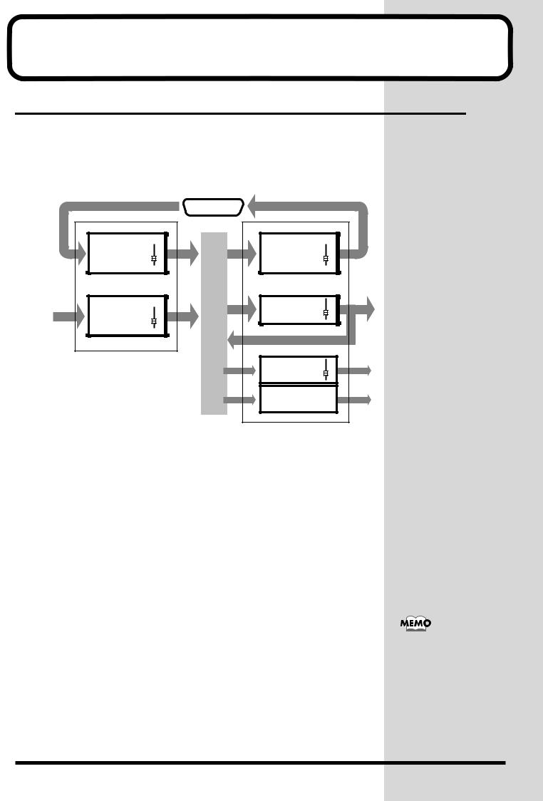
Internal Signal Flow
The diagram below provides an overview of the audio signal flow. For details, refer to the “Block Diagram” attached to the processor (VM-7200/ 7100).
MULTI IN |
1–24 |
INPUT |
1–24 |
1 |
R-BUS |
MULTI OUT |
1–24 |
FLEX BUS MASTER |
1–12 |
B |
U |
S |
MAIN OUT |
L/R |
CUE OUT |
L/R |
2 |
1. Input Channels
There are two input modes to this system – [INPUT] and [MULTI IN].
INPUT...1-24
The following input jacks can be assigned to these channels:
•20 analog input jacks on the VM-7200 mixing processor (10 on VM7100).
•Stereo digital input jacks on the mixing processor (A or B)
•2 analog input jacks on the mixing console (stereo L/R).
MULTI IN...1-24
Multi-channel audio signals can be input from external equipment – such as multi-track recorders – via these channels.
The correspondence between input signal channel numbers and Multi In channels can be re-patched internally.
In order to use Multi In channels, a VM-24E (sold separately) must be connected to the mixing processor in order to add an R-BUS connector I/O terminal (OWNER’S MANUAL for the Processor: p.14).
22

Before Mixing Operations
2. Busses / Output Routes
MULTI OUT
A multiple output channel to which signals from any input channel and/or Flex Bus can be routed. Digital multi-track output to a digital multi-track recorder can be performed by installing an optional VM-24E (sold separately) in the system. You can also send analog track outputs from ASSIGNABLE OUT jacks.
FLEX BUSSES 1-12
A Flex Bus is a multi-purpose bus through which signals can be sent to another bus, to other internal destinations or to external devices. Flex Busses are capable of sending signals from all input channels as well as Flex Busses 1-8. Any ASSIGNABLE OUT, DIGITAL OUTs A and B, and MULTI OUT can be selected for outputting Flex Bus signals to external destinations. If you are using a VM-7200 processor, dedicated output jacks are also available for Flex Busses 5-12.
MAIN OUT
Output of the overall stereo mix containing all desired channels, to be sent to the master recorder or the main PA amplifier. Signals can be sent from all input channels and Flex Busses.
In addition to the dedicated output terminals (MAIN OUT and REC OUT), signals can be directed to any ASSIGNABLE OUT, DIGITAL OUTs A and B, and/or any MULTI OUT.
CUE OUT
Stereo bus used mainly for monitoring. Signals can be sent to the Cue bus from all input channels and Flex Busses.
Cue signals can be output from MONITOR OUT and PHONES jacks to external monitoring amplification equipment. They can also be routed to any ASSIGNABLE OUT, DIGITAL OUTs A and B, or any MULTI OUT.
You can also output other
busses’ signals from
MONITOR OUT jacks.
23

Before Mixing Operations
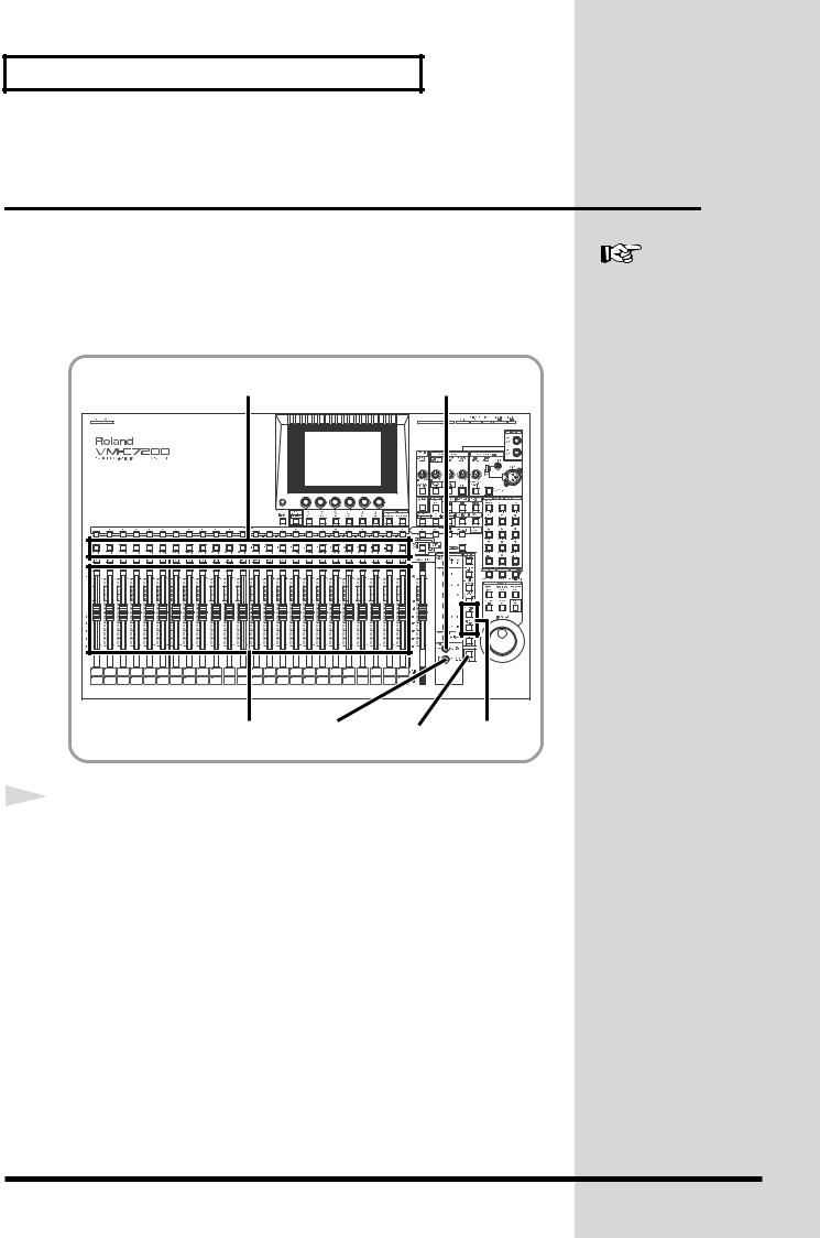
How to Operate This System
When operating this system, you’ll most frequently use the cursor, the knobs [V1]-[V6], and buttons [F1]-[F6] beneath the display.
This chapter explains the display, and how these knobs and buttons interact with the display.
Display
Buttons F1-F6
Cursor buttons
Knobs V1-V6 |
Faders INPUT/MULTI IN buttons
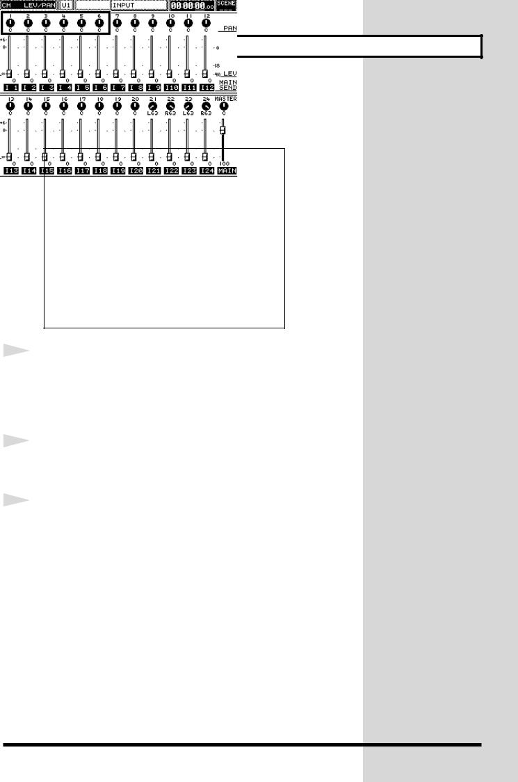
The Display (example)
Screen title |
Parameter icon |
Cursor |
Current time (Time Code) |
Processor currently targeted |
Current page |
Current Section and Channel |
Number of Scene currently |
Name of Channel |
selected |
24

Before Mixing Operations
To Change Parameters
To change the value of a parameter, move the cursor to select a parameter, and use the knobs [V1]-[V6], faders, and/or buttons [F1]-[F6] to change its value, as described below.
To Move the Cursor
The cursor – a bold rectangle on the display – selects a single parameter or group of parameters so that their values can be adjusted. To move the cursor, press CURSOR [UP] [DOWN] [LEFT] [RIGHT].
To Set the Values of Parameters
There are certain rules for setting parameters, as listed below. We recommend you keep them in mind.
• parameters are set by turning knobs [V1]-[V6]. Turn the knob below the parameter you wish to change.
• parameters are set by pressing buttons [F1]-[F6]. Press the button for ON – this highlights the parameter in black on the display
– or OFF (not highlighted) below the parameter you wish to change.
ON OFF
• parameters are set by turning knobs [V1]-[V6] first, and then pressing buttons [F1]-[F6](SET) to confirm the changes. Use the knob and button below the parameter you wish to change. (Some parameters can be set by pressing [F1]-[F6](SET) only.)
•Parameters shown as faders are set using the console’s faders. If the fader indicated is selected by the cursor, you can also change its value by turning the corresponding knobs [V1]-[V6].
To Operate on [INPUT] or [MULTI IN] channels
To set the input source’s gain level and the tone, such as using the equalizer and so on, press [INPUT] or [MULTI IN] to select the type of channel you wish to setup.
With the selected button lit in red, you can control the behavior of each source signal using the console’s faders or display controls.
The cursor does not appear on a display where no cursor selection is needed.
If you want to display or change frequently used parameters, or the value of a single parameter on all of the channels at once, you can do this more easily by using the console’s faders (Owner’s Manual “Useful Functions” p.58).
25

Mixing Operations
Now let’s do some mixing. This chapter describes two-channel – stereo – mixing of connected sources that will be sent out from the system through its MAIN OUT jacks.
Setting the Input Gain
Let’s adjust the input gain levels of all of your connected instruments and so on. (If you are working on digital connected sources, you do not have to read this section.)
Owner’s Manual “Gain, Phantom Power Supply, Phase and Attenuator” (p.68)
|
2 |
1 |
1 |
Press [PREAMP GAIN]. |
|
|
|
[PREAMP GAIN] lights and the “PREAMP GAIN” display appears.
As preset at the factory, all channel numbers on the console correspond to the input numbers on the processor. You may, however, change the channels’ connections or work on multiple channels at once (Owner’s Manual
“Selecting an input channel’s signal source” p.67).
If you selected DIGITAL IN A/B as your source input, these steps will not be necessary.
You can also set the gain level with the cursor and knobs on the display.
26

Mixing Operations
2 |
Use the fader of each channel you wish to adjust to set the |
|
|
|
||
|
The fader, at this point, |
|||||
|
input gain level of its connected microphone/instrument/ |
|||||
|
controls the input gain |
|||||
|
audio device. (+4 to -64dB) |
|
level of each channel. To |
|||
|
Do this by first turning up each instrument’s own output volume as much |
send signals from the Main |
||||
|
out, set the output level of |
|||||
|
as possible so that it produces a strong, loud signal. Next, on the console, |
|||||
|
each channel (go to next |
|||||
|
turn its channel’s input gain level as high as possible within the displayed |
|||||
|
page). |
|||||
|
level-meter range. If the input gain goes beyond OVER, |
appears on the |
|
|
|
|
|
level-meter. |
|
|
|
|
|
|
|
|
|
If you are using a |
||
|
|
|
|
|||
|
|
|
|
condenser microphone or |
||
|
|
|
|
any other similar |
||
|
|
|
|
equipment, activate their |
||
|
|
|
|
PHANTOM power. |
||
|
|
|
|
|
|
|
|
|
|
|
|
|
|
You can also set each channel’s PHASE ON/OF, PHANTOM POWER ON/ OFF and ATTENUATOR if required by the input source.
When you have finished with these settings, you can set the channel levels and L/R stereo pans.
27
Mixing Operations
Setting the Channel Levels and L/R
Pans
Here you can set the output level and L/R pan of each channel in the Main out mix or the Cue bus. You can see each level and pan setting shown numerically on the display.
3,5 |
|
4,5 |
|
3,5 |
2,3 |
SHIFT |
1 |
1 |
Press [INPUT] or [MULTI IN] to select the type of channel you |
|
|
|
wish to set up. |
Owner’s Manual “Setting
up ON/OFF, SEND LEVEL
and PAN for a Channel”
(p.70)
28
2
3
4
5
Mixing Operations
Press [CH LEVEL].
[CH LEVEL] lights in red and the “CH LEV/PAN” display appears.
Use the fader of the channel you wish to adjust to change its
output level.
To set the channel level at 0db (100), hold down [CH LEVEL] and press [CH
EDIT] of the channel you wish to set at 0db.
Press [CH PAN]
[CH PAN] lights in red and the “CH LEV/PAN” display appears.
Use the fader of the channel you wish to adjust to change its
stereo position.
Move the fader upwards for right (R) pan, downwards for left (L) pan.
To set the pan to center, hold down [CH LEVEL] and press [CH EDIT] of the channel you wish to set the pan to center.
To send signals to the Cue bus, hold down [SHIFT] when pressing [CH LEVEL] in Step 2, and when pressing [CH PAN] in Step 4. The buttons will light in green.
When you have finished with these settings, let’s set the master level and stereo balance.
29

Mixing Operations
Setting the Master Level and Master
Stereo Balance
Let’s now set the total output level and stereo balance for the Main out mix
containing all Input and Multi In sources.
3 |
2,4 1 |
1 |
Press [CH LEVEL] to light [CH LEVEL] in red. |
|
|
2 |
Use the [MASTER] fader to set the master level for the Main |
|
|
|
out. |
3 |
Press [CH PAN] to light [CH PAN] in red. |
|
Owner’s Manual “Setting
Master Mix Levels and
Stereo Balance” (p.84)
30
 Loading...