


Before using this unit, carefully read the sections entitled: “USING THE UNIT SAFELY” and “IMPORTANT NOTES” (p. 3; p. 5). These sections provide important information concerning the proper operation of the unit. Additionally, in order to feel assured that you have gained a good grasp of every feature provided by your new unit, Owner’s manual should be read in its entirety. The manual should be saved and kept on hand as a convenient reference.
Copyright © 2009 ROLAND CORPORATION
All rights reserved. No part of this publication may be reproduced in any form without the written permission of ROLAND CORPORATION.
About WARNING and
  CAUTION Notices
Used for instructions intended to alert the user to the risk of death or severe injury should the unit be used improperly.
Used for instructions intended to alert the user to the risk of injury or material damage should the unit be used improperly.
* Material damage refers to damage or other adverse effects caused with respect to the home and all its furnishings, as well to domestic animals or pets.
About the Symbols
The  symbol alerts the user to important instructions or warnings.The specific meaning of the symbol is determined by the design contained within the triangle. In the case of the symbol at left, it is used for general cautions, warnings, or alerts to danger.
The  symbol alerts the user to items that must never be carried out (are forbidden). The specific thing that must not be done is indicated by the design contained within the circle. In the case of the symbol at left, it means that the unit must never be disassembled.
The  symbol alerts the user to things that must be carried out. The specific thing that must be done is indicated by the design contained within the circle. In the case of the symbol at left, it means that the power-cord plug must be unplugged from the outlet.
ALWAYS OBSERVE THE FOLLOWING
• Do not open or perform any internal modifications on the unit.
.......................................................................................................................
•Do not attempt to repair the unit, or replace parts within it (except when this manual provides specific instructions directing you to do so). Refer all servicing to your retailer, the nearest Roland Service Center, or an authorized Roland distributor, as listed on
the “Information” page.
.......................................................................................................................
•Never install the unit in any of the following locations.
•Subject to temperature extremes (e.g., direct sunlight in an enclosed vehicle, near a heating duct, on top of heat-generating equipment); or are
•Damp (e.g., baths, washrooms, on wet floors); or are
•Exposed to steam or smoke; or are
•Subject to salt exposure; or are
•Humid; or are
•This unit, either alone or in combination with an amplifier and headphones or speakers, may be capable of producing sound levels that could cause permanent hearing loss. Do not operate for a long period of time at a high volume level, or at a level that is uncomfortable. If you experience any hearing loss or ringing in the ears, you should immediately stop using the unit, and
consult an audiologist.
.......................................................................................................................
•Exposed to rain; or are
•Dusty or sandy; or are
•Subject to high levels of vibration
and shakiness.
.......................................................................................................................
•Make sure you always have the unit placed so it is level and sure to remain
stable. Never place it on stands that could wobble, or on inclined surfaces.
.......................................................................................................................
3
USING THE UNIT SAFELY
•Do not allow any objects (e.g., flammable material, coins, pins); or
liquids of any kind (water, soft drinks, etc.) to penetrate the unit.
.......................................................................................................................
•Immediately turn the power off, and request servicing by your retailer, the
nearest Roland Service Center, or an authorized Roland distributor, as listed on the “Information” page when:
•If smoke or unusual odor occurs
•Objects have fallen into, or liquid has been spilled onto the unit; or
•The unit has been exposed to rain (or otherwise has become wet); or
•The unit does not appear to operate normally or exhibits a
marked change in performance.
.......................................................................................................................
• In households with small children, an adult should provide supervision
until the child is capable of following all the rules essential for the safe
operation of the unit.
.......................................................................................................................
• Try to prevent cords and cables from becoming entangled. Also, all cords
and cables should be placed so they are out of the reach of children.
.......................................................................................................................
•Never climb on top of, nor place heavy objects on the unit.
.......................................................................................................................
•Disconnect all cords coming from external devices before moving the
unit.
.......................................................................................................................
• Always turn the phantom power off when connecting any device other than condenser microphones that require phantom power. You risk causing damage if you mistakenly supply phantom power to dynamic microphones, audio playback devices, or other devices that don’t require such power. Be sure to check the specifications of any microphone you intend to use by referring to the manual that came with it.
(This instrument’s phanto power: DC 48V, 8mA Max)
.......................................................................................................................
•Protect the unit from strong impact. (Do not drop it!)
.......................................................................................................................
•DO NOT play a CD-ROM disc on a conventional audio CD player. The resulting sound may be of a level that could cause permanent hearing loss. Damage to speakers or other system
components may result.
.......................................................................................................................
4

IMPORTANT NOTES
Power Supply
•Before connecting this unit to other devices, turn off the power to all units. This will help prevent malfunctions and/or damage to speakers or other devices.
Placement
•Using the unit near power amplifiers (or other equipment containing large power transformers) may induce hum. To alleviate the problem, change the orientation of this unit; or move it farther away from the source of interference.
•This device may interfere with radio and television reception. Do not use this device in the vicinity of such receivers.
•Noise may be produced if wireless communications devices, such as cell phones, are operated in the vicinity of this unit. Such noise could occur when receiving or initiating a call, or while conversing. Should you experience such problems, you should relocate such wireless devices so they are at a greater distance from this unit, or switch them off.
•When moved from one location to another where the temperature and/or humidity is very different, water droplets (condensation) may form inside the unit. Damage or malfunction may result if you attempt to use the unit in this condition. Therefore, before using the unit, you must allow it to stand for several hours, until the condensation has completely evaporated.
•Depending on the material and temperature of the surface on which you place the unit, its rubber feet may discolor or mar the surface. You can place a piece of felt or cloth under the rubber feet to prevent this from happening. If
you do so, please make sure that the unit will not slip or move accidentally.
Maintenance
•For everyday cleaning wipe the unit with a soft, dry cloth or one that has been slightly dampened with water. To remove stubborn dirt, use a cloth impregnated with a mild, non-abrasive detergent. Afterwards, be sure to wipe the unit thoroughly with a soft, dry cloth.
•Never use benzine, thinners, alcohol or solvents of any kind, to avoid the possibility of discoloration and/or deformation.
Handling CD-ROMs
•Avoid touching or scratching the shiny underside (encoded surface) of the disc. Damaged or dirty CD-ROM discs may not be read properly. Keep your discs clean using a commercially available CD cleaner.
Copyright
•Recording, duplication, distribution, sale, lease, performance, or broadcast of copyrighted material (musical works, visual works, broadcasts, live performances, etc.) belonging to a third party in part or in whole without the permission of the copyright owner is forbidden by law.
•This product can be used to record or duplicate audio or visual material without being limited by certain technological copy-protection measures. This is due to the fact that this product is intended to be used for the purpose of producing original music or video material, and is therefore designed so that material that does not infringe copyrights belonging to others (for example, your own original works) can be recorded or duplicated freely.
•Do not use this unit for purposes that could infringe on a copyright held by a third party. We assume no responsibility whatsoever with regard to any infringements of third-party copyrights arising through your use of this unit.
5

IMPORTANT NOTES
Additional Precautions
•Use a reasonable amount of care when using the unit’s buttons, sliders, or other controls; and when using its jacks and connectors. Rough handling can lead to malfunctions.
•When connecting / disconnecting all cables, grasp the connector itself—never pull on the cable. This way you will avoid causing shorts, or damage to the cable’s internal elements.
•To avoid disturbing your neighbors, try to keep the unit’s volume at reasonable levels. You may prefer to use headphones, so you do not need to be concerned about those around you (especially when it is late at night).
•When you need to transport the unit, package it in the box (including padding) that it came in, if possible. Otherwise, you will need to use equivalent packaging materials.
•Some connection cables contain resistors. Do not use cables that incorporate resistors for connecting to this unit. The use of such cables can cause the sound level to be extremely low, or impossible to hear. For information on cable specifications, contact the manufacturer of the cable.
*Microsoft, Windows and Windows Vista are registered trademarks of Microsoft Corporation.
*Windows® is known officially as: “Microsoft® Windows® operating system.”
*Apple, Macintosh and Mac OS are registered trademarks of Apple Inc.
*Cakewalk is a registered trademark of Cakewalk, Inc.
*MMP (Moore Microprocessor Portfolio) refers to a patent portfolio concerned with microprocessor architecture, which was developed by Technology Properties Limited (TPL).
Roland has licensed this technology from the TPL Group.
*MPEG Layer-3 audio compression technology is licensed from Fraunhofer IIS Corporation and THOMSON Multimedia Corporation.
*All product names mentioned in this document are trademarks or registered trademarks of their respective owners.
6

Contents |
|
USING THE UNIT SAFELY ................................................................................ |
3 |
IMPORTANT NOTES ........................................................................................ |
5 |
Contents of the Package ................................................................................ |
8 |
Panel Descriptions........................................................................................ |
10 |
Front panel ........................................................................................................................................... |
10 |
Rear panel............................................................................................................................................. |
13 |
Driver Installation and Settings .................................................................. |
15 |
Windows Vista users ......................................................................................................................... |
16 |
Windows XP users.............................................................................................................................. |
20 |
Macintosh users.................................................................................................................................. |
24 |
Verifying that you hear sound....................................................................................................... |
28 |
Basic Connections and Settings................................................................... |
30 |
Basic connections .............................................................................................................................. |
31 |
Connecting a microphone or a guitar ........................................................................................ |
32 |
Connecting a microphone and applying the compressor.................................................. |
34 |
Recording a digital signal into your computer ....................................................................... |
36 |
Recording to an MD or other digital device............................................................................. |
37 |
Appendices.................................................................................................... |
38 |
Driver settings..................................................................................................................................... |
38 |
Driver signing option settings (Windows XP).......................................................................... |
39 |
Reinstalling the driver ...................................................................................................................... |
40 |
Removing the driver ......................................................................................................................... |
40 |
Power management settings ........................................................................................................ |
42 |
System “Performance” settings (Windows).............................................................................. |
43 |
System volume settings .................................................................................................................. |
44 |
About standard driver mode ......................................................................................................... |
45 |
Troubleshooting ........................................................................................... |
46 |
Problems when installing the driver........................................................................................... |
46 |
Problems with settings .................................................................................................................... |
49 |
Problems with playback or recording ........................................................................................ |
50 |
Specifications................................................................................................ |
55 |
Index .............................................................................................................. |
57 |
7
Contents of the Package
After you open the package, please check that all items are present.
If anything is missing, contact your dealer.
■ UA-25EX
■ Owner’s manual
This is the document you’re reading. Keep it at hand for reference when needed.
■ CD-ROMs (2 discs)
*Before you open the included CD-ROM, you must read the “license agreement.” Opening the CDROM will be taken to mean your acceptance of the license agreement.
UA-25EX Driver CD-ROM
This contains the UA-25EX drivers and demo songs.
Cakewalk Production Plus Pack CD-ROM
This package includes:
•DAW software that lets you experience a premium music production environment
•A sampling synthesizer that’s ready for immediate use
For details on using these software, refer to the installation guides and the software help provided on the CD-ROM.
*Use of the demo song supplied with this product for any purpose other than private, personal enjoyment without the permission of the copyright holder is prohibited by law. Additionally, this data must not be copied, nor used in a secondary copyrighted work without the permission of the copyright holder.
*Avoid touching or scratching the shiny underside (encoded surface) of the disc. Damaged or dirty CD-ROM discs may not be read properly. Keep your discs clean using a commercially available CD cleaner.
DO NOT play a CD-ROM disc on a conventional audio CD player. The resulting sound may be of a level that could cause permanent hearing loss. Damage to speakers or other system components may result.
8

Contents of the Package
■ USB cable
Use this cable to connect the UA-25EX to the USB connector of your computer.
*Please use only the included USB cable. If you require a replacement due to loss or damage, please contact the nearest Roland Service Center, or an authorized Roland distributor, as listed on the “Information” page.
■License agreement
This agreement allows you to use certain software whose copyright is the property of Roland Corporation. You must read this before opening the CD-ROMs.
You’ll need to provide the following items
External amplifier, speakers, headphones, and microphone are not included.
The external amplifier, speakers, or headphones that you’ll need in order to listen to sounds that are output via the UA-25EX are not included. Nor is there included a microphone for connection to the UA-25EX to input audio. You’ll need to obtain these items separately.
Cables for connecting to an MD or DAT recorder are not included.
You can use an MD or DAT digital recorder to record digital audio, but a cable for connecting your digital device to the UA-25EX is not included. You’ll need to obtain this separately.
9
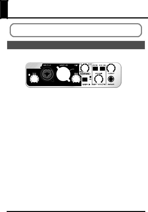
Panel Descriptions
You must install the driver before you connect the UA-25EX to your computer for the first time.
Install the driver as described in “Driver Installation and Settings” (p. 15).
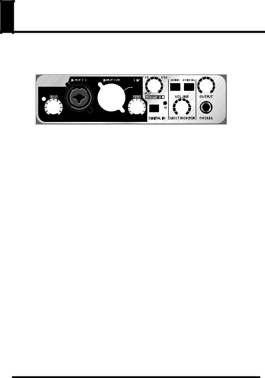
Front panel
|
1 |
3 |
4 5 |
8 |
|
|
9 |
12 |
||||||||||||||||||||||
|
|
|
|
|
|
|
|
|
|
|
|
|
|
|
|
|
|
|
|
|
|
|
|
|
|
|
|
|
|
|
|
|
|
|
|
|
|
|
|
|
|
|
|
|
|
|
|
|
|
|
|
|
|
|
|
|
|
|
|
|
|
|
|
|
|
|
|
|
|
|
|
|
|
|
|
|
|
|
|
|
|
|
|
|
|
|
|
|
|
|
|
|
|
|
|
|
|
|
|
|
|
|
|
|
|
|
|
|
|
|
|
|
|
|
|
|
|
|
|
|
|
|
|
|
|
|
|
|
|
|
|
|
|
|
|
|
|
|
|
|
|
|
|
|
|
|
|
|
|
|
|
|
|
|
|
|
|
|
|
|
|
|
|
|
|
|
|
|
|
|
|
|
|
|
|
|
|
|
|
|
|
|
|
|
|
|
|
|
|
|
|
|
|
|
|
|
|
|
|
|
|
|
|
|
|
|
|
|
|
|
|
|
|
|
|
|
2 |
6 |
7 |
10 11 |
13 |
1.Combo input jacks
These are analog audio input jacks with microphone preamps. They accommodate both XLR type and phone type plugs, allowing you to use the type appropriate for the device you’re connecting. They also support either balanced or unbalanced connections.
Connect a microphone to XLR type jacks. The XLR type jacks can provide 48 V phantom power, allowing you to connect a phantom-powered condenser microphone. In this case, set the rear panel Phantom power switch (23) to the ON position.
XLR type plug
Phone type plug |
TRS phone |
|
type plug |
||
(unblanced) |
||
(balanced) |
||
|
*This instrument is equipped with balanced (XLR/TRS) type jacks. Wiring diagrams for these jacks are shown on the right. Make connections after first checking the wiring diagrams of other equipment you intend to connect.
GND (SLEEVE)
1:GND
2:HOT
3: COLD HOT (TIP)
COLD (RING)
2.Input sensitivity knobs
These adjust the input level of the signals that are input from the front panel combo input jacks (1).
3.Input impedance select switch
This lets you select either high impedance (Hi-Z) or low impedance (Lo-Z) as appropriate for the device you’ve connected to the phone type input jack of combo input jack (1) INPUT 2/R.
If you’ve connected a guitar or bass, turn the input impedance select switch on (pressed inward  ) to select high impedance (Hi-Z). If you’ve connected a synthesizer or an analog audio device, turn the
input impedance select switch off (outward position  ) to select low impedance (Lo-Z). The phone type jack of the combo input jack INPUT 1/L is fixed at low impedance (Lo-Z).
10
Panel Descriptions
1 |
3 |
4 5 |
8 |
|
|
9 |
12 |
||||||||||||||
|
|
|
|
|
|
|
|
|
|
|
|
|
|
|
|
|
|
|
|
|
|
|
|
|
|
|
|
|
|
|
|
|
|
|
|
|
|
|
|
|
|
|
|
|
|
|
|
|
|
|
|
|
|
|
|
|
|
|
|
|
|
|
|
|
|
|
|
|
|
|
|
|
|
|
|
|
|
|
|
|
|
|
|
|
|
|
|
|
|
|
|
|
|
|
|
|
|
|
|
|
|
|
|
|
|
|
|
|
|
|
|
|
|
|
|
|
|
|
|
|
|
|
|
|
|
|
|
|
|
|
|
2 |
6 |
7 |
10 11 |
13 |
4.Compressor/Limiter threshold knob
This adjusts the threshold of the compressor/limiter.
Turning the knob toward the right will lower the level at which the compressor/limiter begins to be applied. If the rear panel compressor/limiter type switch (22) is set to compressor 1 (or 2), the gain (makeup gain) will rise as the threshold level is lowered, producing a fat sound.
Turning this all the way to the left will turn off the compressor/limiter.
*Turning this knob toward the right will strengthen the compressor effect, which may create the impression that the tone is being affected. If this occurs, turn the threshold knob back toward the left until the tonal change is not noticeable.
*If you want to turn the circuit itself completely off, set the rear panel compressor/limiter type switch (22) to the OFF (BYPASS) position.
5.Peak indicator
This indicates the input signal level. Use the input sensitivity knob (2) for each input jack to adjust the input level so that the peak indicator does not light.
If the rear panel compressor/limiter type switch (22) is set to OFF (BYPASS) position, the peak indicator will light red. The compressor/limiter type switch is set to compressor 1, 2 or Limiter position, the peak indicator will light green.
6.Digital input switch
If you want to record from the digital input, turn this ON (pressed inward  ).
).
This allows you to synchronize with the external digital device connected to the digital input connector (17).
|
|
|
Digital input switch |
Status |
|
|
|
|
|
|
|
ON |
|
with a digital device connected to |
The input from the digital input connector (17) is sent to the |
||
|
|||||
the digital input connector |
computer (Digital input mode). |
||||
|
|||||
|
|
|
|
|
|
OFF |
|
|
|
The input from the combo input jacks (1) is sent to the computer. |
|
|
|
|
|||
|
|
|
|
|
|
ON |
|
|
with no digital device connected |
The audio signal (sound) that is output from the computer via USB |
|
|
|
||||
|
|
will pass through the UA-25EX and return to the computer |
|||
to the digital input connector |
|||||
(LoopBack mode). |
|||||
|
|
|
|
|
|
*In digital input mode you will not hear the sound from the computer. The settings of the direct monitor section will be ignored. This means that the direct monitor switch (9), STEREO/MONO select switch (8), and direct monitor volume (10) will not do anything.
11

Panel Descriptions
7.USB indicator
This will light blue if the UA-25EX is connected to your computer via the USB cable and the computer has correctly recognized the UA-25EX.
8.STEREO/MONO select switch (direct monitor section)
This selects whether the input signal from the combo input jacks (1) will be monitored in stereo (STEREO) or in monaural (MONO).
If you’ve connected a guitar only to INPUT 2/R, set this to monaural (  pressed inward). Even if this is set to monaural, the audio signal sent via USB to your computer will be stereo.
* If the digital input switch (6) is on, operating the STEREO/MONO select switch will not do anything.
9.Direct monitor switch (direct monitor section)
This selects whether the input signal from the combo input jacks (1) will be output from the headphone jack (13) and master output jacks (14). The direct monitor ON and OFF will change whenever this switch is pushed. The direct monitor ON/OFF status can be controlled directly from ASIO 2.0 compatible software such as Cubase.
Direct monitor switch |
Status |
|
|
|
|
ON |
The input signal will be output. |
|
(direct monitor indicator lit) |
||
|
||
|
|
|
OFF |
The input signal will not be output. |
|
Use the OFF setting if the audio signal is being passed “through” within |
||
(direct monitor indicator unlit) |
the computer, or if you’ve connected a mixer and are monitoring the |
|
|
input signal directly from the mixer’s output. |
|
|
|
*In digital input mode (p. 11), direct monitor is always ON, regardless of the direct monitor switch operation.
10.Direct monitor volume (direct monitor section) knob
This adjusts the volume at which the input signal from the combo input jacks (1) is output from the headphone jack (13) and master output jacks (14).
If this is turned all the way to the right, the monitored sound will be twice volume (+6 dB).
11.Direct monitor indicator (direct monitor section)
This will light when direct monitor is on, and will be unlit when it is OFF. If the digital input switch
(6) is turned on, direct monitor will be OFF automatically and the direct monitor indicator will be extinguished.
12.Output volume knob
This adjusts the volume that is output from the headphone jack (13) and master output jacks (14).
13.Headphone jack
Accepts connection of headphones. This jack will output the same sound as the master output jacks (14). Sound will be output from the master output jacks even if headphones are connected.
12

Panel Descriptions
Rear panel
15 |
19 |
22 |
|
|
|
|
|
|
|
|
|
|
|
|
|
|
|
|
|
|
|
|
|
|
|
|
|
|
|
|
|
|
|
|
|
|
|
|
|
|
|
|
|
|
|
|
|
|
|
|
|
|
|
|
|
|
|
|
|
|
|
|
|
|
|
|
|
|
|
|
|
|
|
|
|
|
|
|
|
|
|
|
|
|
|
|
|
|
|
|
|
|
|
|
|
|
|
|
|
|
|
|
|
|
|
|
|
|
|
|
|
|
|
|
|
|
|
|
|
|
|
|
|
|
|
|
|
|
|
|
|
|
|
|
|
|
|
|
|
|
|
|
|
|
|
|
|
|
|
|
|
|
14 |
16 17 |
18 |
20 |
|
21 |
23 |
||||||||||||||||||
14.Master output jacks (TRS balanced type, RCA phono type)
These are output jacks for analog audio signals. The phone jacks and RCA phono jacks output the same signal. You may use whichever type of jack is appropriate for the connected device or the type of cable.
*The TRS balanced master output jacks are wired as shown on the right. Before you make connections, check the wiring of the equipment you’re connecting.
GND (SLEEVE)
HOT (TIP) 


 COLD (RING)
15.Ground lift switch
Normally, you can leave this in the NORMAL (NOR) position. If you experience noise due to a ground loop, you may be able to eliminate the noise by setting this to the LIFT position, so that the sleeve (SLEEVE) pin of the master output TRS balanced jacks is disconnected from ground.
Mater output jack 
 (TRS balanced type)
NOR
LIFT
16.Digital output connector (optical)
This is an output connector for digital audio signals. Use this to digitally output audio signals to a digital audio device such as an MD or DAT. Use an optical cable to make connections.
17.Digital input connector (optical)
This is a input connector for digital audio signals. Use this to digitally input audio signals from a digital audio device such as a CD, MD, or DAT. Use an optical cable to make connections.
18.MIDI IN/OUT connectors
These are MIDI connectors which transmit and receive MIDI messages between computer.
* The MIDI IN/OUT connectors are not available, if you’re using the UA-25EX in Standard driver mode (p. 45).
19.Sample rate select switch
This specifies the sample rate at which audio is recorded or played back. If you change the setting of the sample rate select switch, you must close all software, disconnect the USB cable that connects the UA-25EX to your computer, and then reconnect the USB cable.
* If you are using Standard driver mode (the Advanced Driver switch turned off), the sample rate is fixed at 44.1 kHz regardless of the sample rate select switch setting.
* If you want to use 96 kHz, set the switch to “96R” while recording and to “96P” while playing back.
13

Panel Descriptions
20.USB connector
Use a USB cable to connect this to your computer.
21.Advanced driver switch
This switches the operating mode between Advanced mode (ON) and Standard mode (OFF). Normally, you can leave this set to Advanced mode (ON).
* If you change this setting, you must disconnect the UA-25EX’s USB cable from your computer, and then re-connect it.
Switch |
Explanation |
|
|
ON |
In this mode you can use the dedicated driver, which allows you to play and record |
(Advanced mode) |
audio with high quality and stable timing. |
In this mode you can use the standard audio driver provided by your operating system. This is convenient if you don’t have the dedicated driver, or if you’re unable
OFF
to install the dedicated driver. However, the following limitations apply.
(Standard driver mode)
• The UA-25EX will operate at 44.1 kHz/16-bit mode regardless of the setting of the sample rate select switch (19).
•ASIO drivers are not supported.
•The MIDI IN/OUT connectors (18) cannot be used.
22.Compressor/Limiter type switch
This selects the type of hardware compressor/limiter that is applied to the input signal from the combo input jacks (1). Use the compressor/limiter threshold knob (4) to adjusts the threshold of the compressor/limiter.
The UA-25EX provides two type of compressors, each type have different attack time.
Switch |
Explanation |
|
|
|
|
Compressor 1 |
A compressor with a short attack time, suitable for vocals. |
|
(COMP 1) |
||
|
||
|
|
|
Compressor 2 |
A compressor with a long attack, suitable for recording instruments such as percussion or |
|
(COMP 2) |
acoustic guitar. |
|
|
|
|
Limiter |
This applies mild compression when an unexpected, high-volume signal is input, |
|
preventing clipping noise from occurring before the AD converter. |
||
(LIMIT) |
||
* Clipping noise will occur if the input exceeds the range of the limiter. |
||
|
||
|
|
|
OFF |
The compressor/limiter circuit will be completely bypassed. |
|
(BYPASS) |
||
|
||
|
|
23.Phantom power switch
This is an ON/OFF switch for the phantom power that is supplied to the XLR connectors of the front panel combo input jacks (1).
* You must leave the phantom power turned off unless condenser microphones requiring phantom power are connected to the XLR connectors. Supplying phantom power to a dynamic microphone or to an audio playback device may cause malfunctions. For details on the requirements of your microphone, refer to its owner’s manual.
* The UA-25EX’s phantom power supply: DC 48 V, 8 mA maximum.
14

Driver Installation and Settings
The installation procedure and the settings will differ depending on your system. To perform the installation and make settings, follow the three steps listed below for your system.
|
Windows |
Windows XP |
Mac OS X |
|
Vista |
||
|
|
|
|
1. driverInstall the |
p. 16 |
p. 20 |
p. 24 |
Input/output |
|
|
p. 25 |
2. device settings |
p. 18 |
p. 22 |
p. 26 |
Verifying that you |
p. 28 |
p. 28 |
p. 28 |
3. hear sound |
|
|
|
What is a driver?
A driver is software that transfers data between the UA-25EX and the application software on your computer when the UA-25EX is connected to your computer. The driver sends data from your application software to the UA-25EX, and routes data from the UA-25EX to your application software.
If you want to use the UA-25EX in Standard driver mode, refer to “About standard driver mode” (p. 45).
15
Driver Installation and Settings
Windows Vista users
Steps to be performed on the UA-25EX itself are marked by a  symbol. Do not connect the UA-25EX to your computer until you are directed to do so.
Installing the driver
1
Start up Windows without the UA-25EX connected.
* Disconnect all USB cables other than those for a USB keyboard and/or USB mouse (if used).
2
Close all currently running software.
3
Insert the included “UA-25EX Driver CD-ROM” into your CD-ROM drive.
* If the auto-play dialog appears, click “Open folder to see files.”
4
On the CD-ROM, navigate to the Driver Vista folder, and double-click the Setup icon.
*If a message saying “Driver installation must be performed by an administrator” appears, log on to Windows as a user whose account has administrative privileges, and perform the installation again.
5
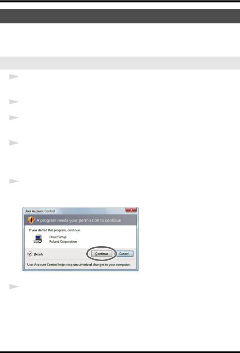
A confirmation screen regarding user account control will appear. Click [Continue].
6
The screen will indicate “UA-25EX Driver will be installed on your computer.”
Click [Next].
* If any other message appears, proceed as directed by the message.
16

Driver Installation and Settings
7
To begin the installation, click [Next] once again. Installation will begin.
If a dialog box related to Windows Security appears, click [Install].
The screen will indicate “Ready to install the driver.”
* If any other message appears, proceed as directed by the message.
8
Operation of the UA-25EX Set the UA-25EX’s Advanced driver switch to the ON position.
*If the Advanced driver switch is set to OFF, the installation will not take place as described in the following procedure.
9
Operation of the UA-25EX Use a USB cable to connect the UA-25EX to your computer.
*This unit is equipped with a protection circuit. A brief interval (a few seconds) after connecting the USB cable is required before the unit will operate normally.
10
The message “Installing device driver software” will appear in the lower right corner of the screen, and the driver will be installed automatically.
*It may take some time (ten seconds or more) until the message appears.
*If any other message appears, note the content of the message and close it.
11
When installation has been completed, the Driver Setup dialog box will indicate “Installation has been completed.”
Click [Close] to close the Driver Setup dialog box.
If the System Settings Change dialog box appears, click [Yes]. Windows will automatically restart.
Next, you need to set your software so it can use the UA-25EX.
17

Driver Installation and Settings
Input/output device settings
In order to use the UA-25EX with your software, you’ll need to select the UA-25EX as the audio and MIDI input/output device. For details on how to do this, refer to the documentation for your software.
*If you’re unable to select the UA-25EX as the audio input/output device in your software, it may be that a problem has occurred. Refer to “Problems with settings” (p. 49) in the Troubleshooting section.
Audio input/output device
Audio output device |
OUT (UA-25EX) |
Audio input device |
IN (UA-25EX) |
*If you’re using ASIO compatible software, select the UA-25EX in the ASIO settings of your software.
MIDI input/output device
MIDI output device |
UA-25EX |
MIDI input device |
UA-25EX |
*The Windows Media Player included with Windows Vista cannot use the UA-25EX’s MIDI input/ output device.
Settings when using the UA-25EX in Windows Media Player
Some software such as Windows Media Player will use the system default playback/recording device for its audio input/output device.
Here’s how to specify the UA-25EX as the system default playback device so that it can be used with Windows Media Player.
*In a later step, you’ll use Windows Media Player to play back sample data. Be sure to make the settings described below.
1
Open the Control Panel, click the Hardware and Sound and click Sound. * If you’re using the Classic view, double-click Sound.
2
Open the Playback tab, select the UA-25EX’s OUT, and click [Set Default].
3
Click [OK] to complete the setting.
*If you select the UA-25EX as the default playback device, audio alerts and other sounds from Windows will also be output from the UA-25EX, and therefore will not be heard from your computer’s speakers.
18

Driver Installation and Settings
Caution when recording or playing back with your software
Check the following points before you use the UA-25EX to record or play back.
•Connect the UA-25EX to your computer before you start up the software you’re using.
•Do not disconnect the UA-25EX’s USB cable from your computer while your software is running. Close the software you’re using before you disconnect the UA-25EX’s USB cable from your computer.
This completes driver installation and settings.
Next, verify that you hear sound from the UA-25EX. “Verifying that you hear sound” (p. 28).
19
Driver Installation and Settings
Windows XP users
Steps to be performed on the UA-25EX itself are marked by a  symbol. Do not connect the UA-25EX to your computer until you are directed to do so.
Installing the driver
1
Start up Windows without the UA-25EX connected.
* Disconnect all USB cables other than those for a USB keyboard and/or USB mouse (if used).
2
Close all currently running software.
3
Insert the included “UA-25EX Driver CD-ROM” into your CD-ROM drive.
4
In the CD-ROM, navigate to the Driver XP folder, and double-click the Setup icon.
*If the “Install Program As Other User” dialog box appears, click [Cancel] to terminate the installation, log on to Windows using an administrator account, and perform the installation once again.
5
The screen will indicate “UA-25EX Driver will be installed on your computer.” Click [Next].
* If any other message appears, proceed as directed by the message.
6
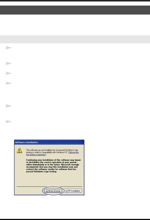
To begin the installation, click [Next].
If the Software Installation dialog box appears, click [Continue Anyway] to proceed with the installation.
*If you are unable to proceed, click [OK] to halt the installation, and then change the settings as described in “Driver signing option settings (Windows XP)” (p. 39).
The screen will indicate “Ready to install the driver.”
* If any other message appears, proceed as directed by the message.
20
 Loading...