


Owner’s Manual
Thank you, and congratulations on your choice of the Roland VGA-7 V-Guitar
Amplifier.
Before using this unit, carefully read the sections entitled:
“IMPORTANT SAFETY INSTRUCTIONS” (page 2)
“USING THE UNIT SAFELY” (page 3–4)
“IMPORTANT NOTES” (page 8–9)
These sections provide important information concerning the proper operation of the unit.
Additionally, in order to feel assured that you have gained a good grasp of every feature provided by your new unit, this manual should be read in its entirety. The manual should be saved and kept on hand as a convenient reference.
Conversions Used in This Manual
●Words enclosed in square brackets [ ] indicate panel buttons or knobs. (Example)
[SYSTEM]: |
SYSTEM button |
[BASS]: |
BASS knob |
● (p. **) indicates a reference page.
Copyright © 2000 ROLAND CORPORATION
All rights reserved. No part of this publication may be reproduced in any form without the written permission of ROLAND CORPORATION.
CAUTION
RISK OF ELECTRIC SHOCK
DO NOT OPEN
ATTENTION: RISQUE DE CHOC ELECTRIQUE NE PAS OUVRIR
CAUTION: TO REDUCE THE RISK OF ELECTRIC SHOCK,
DO NOT REMOVE COVER (OR BACK).
NO USER-SERVICEABLE PARTS INSIDE.
REFER SERVICING TO QUALIFIED SERVICE PERSONNEL.
The lightning flash with arrowhead symbol, within an equilateral triangle, is intended to alert the user to the presence of uninsulated “dangerous voltage” within the product’s enclosure that may be of sufficient magnitude to constitute a risk of electric shock to persons.
The exclamation point within an equilateral triangle is intended to alert the user to the presence of important operating and maintenance (servicing) instructions in the literature accompanying the product.
INSTRUCTIONS PERTAINING TO A RISK OF FIRE, ELECTRIC SHOCK, OR INJURY TO PERSONS.
IMPORTANT SAFETY INSTRUCTIONS SAVE THESE INSTRUCTIONS
WARNING - When using electric products, basic precautions should always be followed, including the following:
1.Read these instructions.
2.Keep these instructions.
3.Heed all warnings.
4.Follow all instructions.
5.Do not use this apparatus near water.
6.Clean only with a damp cloth.
7.Do not block any of the ventilation openings. Install in accordance with the manufacturers instructions.
8.Do not install near any heat sources such as radiators, heat registers, stoves, or other apparatus (including amplifiers) that produce heat.
9.Do not defeat the safety purpose of the polarized or grounding-type plug. A polarized plug has two blades with one wider than the other. A grounding type plug has two blades and a third grounding prong. The wide blade or the third prong are provided for your safety. When the provided plug does not fit into your outlet, consult an electrician for replacement of the obsolete outlet.
10.Protect the power cord from being walked on or pinched particularly at plugs, convenience receptacles, and the point where they exit from the apparatus.
11.Only use attachments/accessories specified by the manufacturer.
12.Never use with a cart, stand, tripod, bracket, or table except as specified by the manufacturer, or sold with the apparatus. When a cart is used, use caution when moving the cart/apparatus combination to avoid injury from tip-over.
13.Unplug this apparatus during lightning storms or when unused for long periods of time.
14.Refer all servicing to qualified service personnel. Servicing is required when the apparatus has been damaged in any way, such as power-supply cord or plug is damaged, liquid has been spilled or objects have fallen into the apparatus, the apparatus has been exposed to rain or moisture, does not operate normally, or has been dropped.
For the U.K.
WARNING: THIS APPARATUS MUST BE EARTHED
IMPORTANT: THE WIRES IN THIS MAINS LEAD ARE COLOURED IN ACCORDANCE WITH THE FOLLOWING CODE. GREEN-AND-YELLOW: EARTH, BLUE: NEUTRAL, BROWN: LIVE
As the colours of the wires in the mains lead of this apparatus may not correspond with the coloured markings identifying the terminals in your plug, proceed as follows:
The wire which is coloured GREEN-AND-YELLOW must be connected to the terminal in the plug which is marked by the letter E or by the safety earth symbol or coloured GREEN or GREEN-AND-YELLOW.
The wire which is coloured BLUE must be connected to the terminal which is marked with the letter N or coloured BLACK. The wire which is coloured BROWN must be connected to the terminal which is marked with the letter L or coloured RED.
2
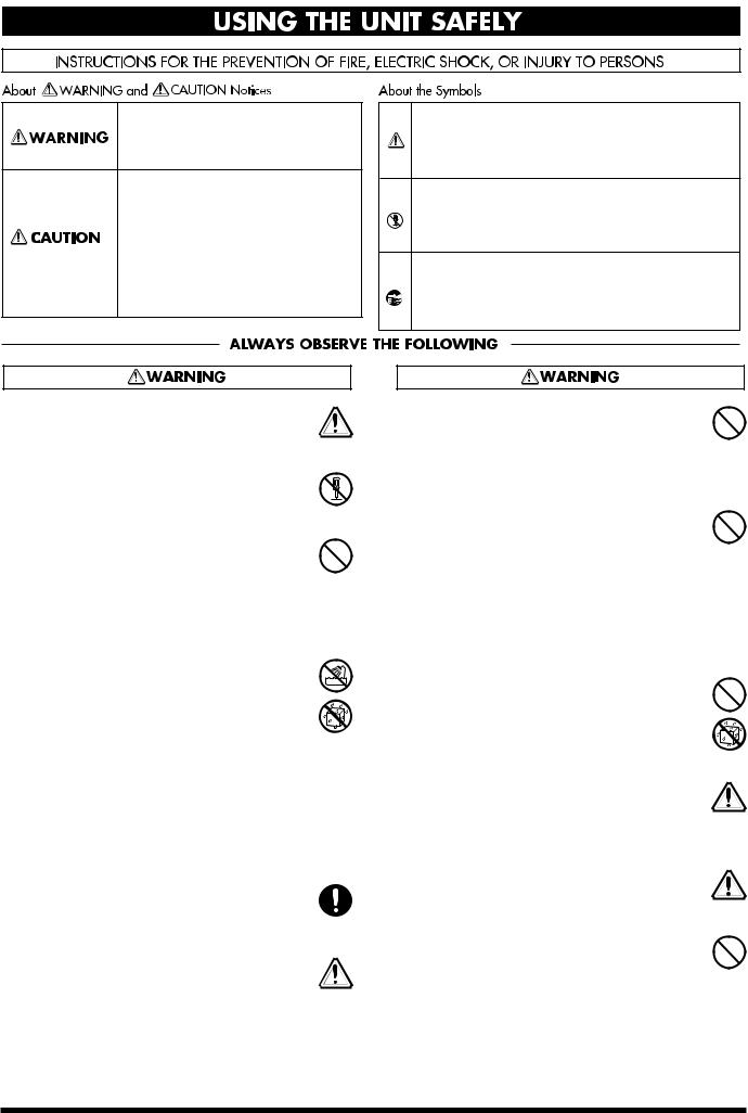
Used for instructions intended to alert the user to the risk of death or severe injury should the unit be used improperly.
Used for instructions intended to alert the user to the risk of injury or material damage should the unit be used improperly.
* Material damage refers to damage or other adverse effects caused with respect to the home and all its furnishings, as well to domestic animals or pets.
•Before using this unit, make sure to read the instructions below, and the Owner’s Manual.
..........................................................................................................
• Do not open or perform any internal modifications on the unit.
..........................................................................................................
•Do not attempt to repair the unit, or replace parts within it (except when this manual provides specific instructions directing you to do so). Refer all servicing to your retailer, the nearest Roland Service Center, or an authorized Roland
distributor, as listed on the "Information" page.
..........................................................................................................
• Never use or store the unit in places that are:
• Subject to temperature extremes (e.g., direct sunlight in an enclosed vehicle, near a heating duct, on top of heat-generating equipment); or are
•Damp (e.g., baths, washrooms, on wet floors); or are
•Humid; or are
•Exposed to rain; or are
•Dusty; or are
•Subject to high levels of vibration.
..........................................................................................................
•Make sure you always have the unit placed so it is level and sure to remain stable. Never place it on stands that could wobble, or on inclined surfaces.
..........................................................................................................
• The unit should be connected to a power supply only of the type described in the operating instructions, or as marked on the unit.
..........................................................................................................
The symbol alerts the user to important instructions or warnings.The specific meaning of the symbol is determined by the design contained within the triangle. In the case of the symbol at left, it is used for general cautions, warnings, or alerts to danger.
The  symbol alerts the user to items that must never be carried out (are forbidden). The specific thing that must not be done is indicated by the design contained within the circle. In the case of the symbol at left, it means that the unit must never be disassembled.
The ● symbol alerts the user to things that must be carried out. The specific thing that must be done is indicated by the design contained within the circle. In the case of the symbol at left, it means that the powercord plug must be unplugged from the outlet.
•Do not excessively twist or bend the power cord, nor place heavy objects on it. Doing so can damage the cord, producing severed elements and
short circuits. Damaged cords are fire and shock hazards!
..........................................................................................................
•This unit, either alone or in combination with an amplifier and headphones or speakers, may be capable of producing sound levels that could cause permanent hearing loss. Do not operate for a long period of time at a high volume level, or at a level that is uncomfortable. If you experience any hearing loss or ringing in the ears, you should
immediately stop using the unit, and consult an audiologist.
..........................................................................................................
•Do not allow any objects (e.g., flammable material, coins, pins); or liquids of any kind (water, soft drinks, etc.) to penetrate the unit.
..........................................................................................................
•In households with small children, an adult should provide supervision until the child is capable of following all the rules essential for the
safe operation of the unit.
..........................................................................................................
• Protect the unit from strong impact. (Do not drop it!)
..........................................................................................................
•Do not force the unit’s power-supply cord to share an outlet with an unreasonable number of other devices. Be especially careful when using extension cords—the total power used by all devices you have connected to the extension cord’s outlet must never exceed the power rating
(watts/amperes) for the extension cord. Excessive loads can cause the insulation on the cord to heat up and eventually melt through.
..........................................................................................................
3
•Before using the unit in a foreign country, consult with your retailer, the nearest Roland Service Center, or an authorized Roland distributor, as
listed on the "Information" page.
..........................................................................................................
• The unit should be located so that its location or position does not interfere with its proper ventilation.
..........................................................................................................
• Always grasp only the plug on the power-supply
cord when plugging into, or unplugging from an outlet.
..........................................................................................................
• Try to prevent cords and cables from becoming entangled. Also, all cords and cables should be placed so they are out of the reach of children.
..........................................................................................................
•If the unit could become a hazard if it moves, all caster wheels should be removed once the unit has
been placed at the place of installation, or has been loaded onto a vehicle.
..........................................................................................................
•Never climb on top of, nor place heavy objects on the unit.
..........................................................................................................
• Never handle the power cord or its plug with wet
hands when plugging into, or unplugging from, an outlet.
..........................................................................................................
• Before moving the unit, disconnect the power
plug from the outlet, and pull out all cords from external devices.
..........................................................................................................
• Before cleaning the unit, turn off the power and unplug the power cord from the outlet.
..........................................................................................................
• Whenever you suspect the possibility of lightning
in your area, pull the plug on the power cord out of the outlet.
..........................................................................................................
4

Contents
IMPORTANT SAFTY INSTRUCTIONS |
......2 |
USING THE UNIT SAFELY ........................ |
3 |
Main Features ............................................ |
6 |
IMPORTANT NOTES.................................. |
8 |
Attaching and Removing the Casters .................... |
9 |
Basic Opration ......................................... |
10 |
Preparations for using the VGA-7........................ |
12 |
Attaching the GK-2A to your guitar ................ |
12 |
About the GK-2A select switch......................... |
12 |
About the SYNTH VOL knob |
|
of the GK-2A........................................................ |
12 |
Making Connections ............................... |
13 |
Turning the Power On and Off ............................ |
13 |
Make settings for the divided pickup .... |
14 |
Specify the pickup type |
|
(1 GK TYPE).............................................................. |
15 |
Specify the direction in which the |
|
pickup is attached (2 DIRECTION) ..................... |
15 |
Specify the scale length |
|
(3 SCALE) .................................................................. |
16 |
Set the length from the pickup |
|
to the bridge (4 PICKUP-BRIDGE)...................... |
16 |
Adjusting the Pickup Sensitivity |
|
for Each String (5 SENS) ........................................ |
17 |
Matching the phase of the divided pickup |
|
and the guitar pickup (6 PHASE) ......................... |
18 |
Specify the function |
|
of the S1/S2 switch (7 S1/S2).................................. |
19 |
Setting the Output Level |
|
of the COSM Guitar (8 LEVEL) ............................ |
19 |
TUNER ...................................................... |
20 |
Setting the Tuner ..................................................... |
20 |
Specify the standard pitch (1 PITCH) .............. |
20 |
Setting the output level |
|
of the tuning sound (2 LEVEL) ......................... |
20 |
Tuning your guitar .................................................. |
21 |
About Patch ............................................. |
22 |
Switching the Patches............................................. |
22 |
Direct Number Button........................................ |
22 |
Changing Patch Settings ....................................... |
23 |
Selecting variations............................................ |
23 |
Checking the settings of a knob ....................... |
23 |
Saving your modifications in a patch |
|
(Write) ....................................................................... |
24 |
Manual Mode .......................................................... |
24 |
Panel Descriptions.................................. |
25 |
Front Panel ............................................................... |
25 |
COSM Guitar Section (COSM GUITAR) ........ |
25 |
COSM Amplifier Section |
|
(COSM AMPLIFIER) ......................................... |
28 |
Effects Section (EFFECTS) ................................ |
30 |
Master Section .................................................... |
34 |
Rear Panel ................................................................ |
35 |
System setting ........................................ |
38 |
Procedure.................................................................. |
38 |
TUNER...................................................................... |
38 |
NOISE SUPRESSOR.............................................. |
38 |
Foot Switch (FOOT SW)........................................ |
39 |
Expression Pedal (EXP PEDAL)........................... |
39 |
MIDI.......................................................................... |
40 |
Transmitting/receiving VGA-7 settings......... |
40 |
MIDI OUT ........................................................... |
42 |
Operating the VGA-7 with the FC-200 ...... |
43 |
Initializing the FC-200 from the VGA-7............. |
43 |
Connecting the VGA-7 and the FC-200 .............. |
43 |
Functions That Can Be Controlled |
|
with the FC-200 ....................................................... |
44 |
In Program Change Mode ................................ |
44 |
In Control Change Mode .................................. |
44 |
Appendices.............................................. |
46 |
If You Think There Might Be a Problem |
|
(Troubleshooting)................................................... |
46 |
Restoring the Factory Settings ............................. |
47 |
Changing the MIDI Settings ................................ |
48 |
Effect connection order.......................................... |
49 |
Block diagram.......................................................... |
49 |
MIDI Implementation Chart................................ |
50 |
Specifications .......................................................... |
51 |
Index......................................................... |
53 |
5

Main Features
The VGA-7, a V-guitar amplifier with a GK input, affords a new dimension in sound-creation potential, through its combination of COSM guitars, COSM amplifiers, and effects. Additionally, if offers a memory storage feature, and stereo output (65 + 65 W).
The two-way speaker system provides 12-inch speakers and horn tweeters in a bass-reflex cabinet, producing richly expressive sound over a broad range, from powerful lows to sparkling highs.
COSM Guitar
●The pitch and envelope data that the divided pickup extracts from the guitar’s vibrations are used to create 26 types of realistic tones, ranging from standard electric guitar to acoustic guitar, and on–to even completely new dimensions in sound.
●You can switch pickups and pickup position as appropriate for the type of guitar. For acoustic guitars, you can select piezo pickup or mic’ed sound.
●The Tuning function (six-string independent) provided by the VGA-7 allows you to play in open tunings or Nashville tuning without changing the actual tuning of your guitar. You can also switch instantly to 12-string guitar tuning.
Each individual string can also be tuned freely.
●Digital Capo function lets you use hitherto-impossible
“negative” fret settings.
COSM Amplifier
●In addition to classic, solid-state and vacuum tube units, full-range amps ideal for acoustic instruments are also provided, giving you a total of twenty different guitar amp sound simulations.
●Gain/volume/3-band equalizer/presence controls let you fine-tune your sound even more. All of these functions are adjusted according to the unique characteristics of each amp type.
●Speaker Modeling function simulates the characteristics of different cabinets. You can use simulations of classic models of speaker cabinets, or combine speakers and cabinets in new and creative ways.
Effects
●Four kinds of effects are offered onboard: EFX, delay, chorus, and reverb. All four can be used simultaneously. You can also use a foot switch to switch each effect on/ off.
●As the EFX, one of the following six can be selected: wah, slow gear, compressor, tremolo, phaser, or flanger.
●The delay supports tap input, making it easy to set the delay time. The Delay Hold function lets you repeatedly play back a recorded phrase.
●Chorus features the richly spacious air-mixed chorus made famous by the Roland JC series.
Memory Storage Feature
A whole string of settings, calling for things such as a change in guitar, in the tuning, in the amp, or a different choice of effects can be stored as “patches” in memory. Then, during performance, simply call up the patch, and you’ve instantly selected just the settings you need.
In addition to eighty pre-programmed “preset” patches, another eighty “user” patches can be programmed with your own settings, for a total of 160 patches at your fingertips.
Easy Operation
Buttons and knobs are located for easy operation, making everything from patch changes to sound editing quick and intuitive.
6

Main Features
Broad Expandability
●Stereo external input jacks are provided, allowing you to mix the sound of the VGA-7 with an external sound source, such as a guitar synthesizer. Stereo line out jacks convenient for recording are also provided.
●The foot control jack lets you use your feet to select patches or turn effects on/off. You can also connect an expression pedal to control volume or wah.
●MIDI connectors allow VGA-7 patch changes and other operations to be controlled from an external MIDI device. You can also transmit VGA-7 settings to an external MIDI device to be saved.
■ Sound Modeling
Roland believes that the final evaluation of an electric guitar’s sound should not be based only on sound output from the guitar itself, but should also include the sound that passes through the guitar amps, speakers, and other equipment.
To achieve this, it’s necessary to simulate all the steps along the way — from the moment a guitar string is plucked, until the time the sound reaches the ears — thereby re-creating the sound. Roland has made it possible to re-create these steps with this latest sound modeling technology — in other words, other means are used to make a virtual model of the physical structures and materials that actually exist.
■ COSM
The new Composite Object Sound Modeling (COSM) advanced by Roland combines a number of sound modeling technologies to create even newer sounds.
COSM is able to combine optimized sound models for various objects to simulate anything from existing musical instruments to sound-producing structures that could not physically exist in the real world.
COSM GUITAR/COSM AMPLIFIER
COSM guitar/COSM amplifier are modeling technologies that can reproduce the sounds of any existing guitar. This includes the following.
•Electronic Modeling, which simulates all characteristics which can be attributed to the use of vacuum tubes, transistors, and all other electronic circuitry.
•Magnetic Modeling, which simulates all the characteristics which can be produced as a result of using pickups, transformers, speakers, and other electromagnetic parts.
•Physical Modeling, which simulates all the characteristics that are produced as a result of the use of certain types of materials to make a guitar, including the kind of wood, metal parts, or finish that are used.
In addition, COSM guitar is able to produce completely new sounds that never existed before. The numerous harmonics contained in the sound from the vibrating strings (the sound source) can be radically emphasized, added to, or removed, in order to create totally new guitar sounds.
A guitarist conveys musical expression through string vibration. Vibrating strings carry a great deal of information about the dynamics of a performance, including that which expresses the way in which strings have been pressed, the location at which they’ve been picked, the position of the pick, and the kind of vibrato that's been used. The V-Guitar system uses the string vibration itself (which contains all of this performance information) as the sound source, and can create not only previously existing guitar sounds, but also completely new sounds. One great advantage of this system is that it preserves the playing dynamics of the guitarist, as they are conveyed by the vibration of the string.
7

IMPORTANT NOTES
291b
In addition to the items listed under “IMPORTANT SAFETY INSTRUCTIONS” and “USING THE UNIT SAFELY” on pages 2 and 3–4, please read and observe the following:
Power Supply
301
•Do not use this unit on the same power circuit with any device that will generate line noise (such as an electric
motor or variable lighting system).
307
•Before connecting this unit to other devices, turn off the power to all units. This will help prevent malfunctions and/or damage to speakers or other devices.
Placement
351
•Using the unit near power amplifiers (or other equipment containing large power transformers) may induce hum. To alleviate the problem, change the orientation of this unit; or move it farther away from the source of inter-
ference.
352
•This device may interfere with radio and television reception. Do not use this device in the vicinity of such
receivers.
354a
•Do not expose the unit to direct sunlight, place it near devices that radiate heat, leave it inside an enclosed vehicle, or otherwise subject it to temperature extremes.
Excessive heat can deform or discolor the unit.
355
• To avoid possible breakdown, do not use the unit in a wet area, such as an area exposed to rain or other moisture.
356
•Do not allow rubber, vinyl, or similar materials to remain on the piano for long periods of time. Such objects can
discolor or otherwise harmfully affect the finish.
357
•Do not put anything that contains water (e.g., flower vases) on the piano. Also, avoid the use of insecticides, perfumes, alcohol, nail polish, spray cans, etc., near the unit. Swiftly wipe away any liquid that spills on the unit using a dry, soft cloth.
•During operation, this device must be placed at a distance of no less than 50 cm from any walls.
•Do not allow objects to remain on top of the unit while it is in operation.
•If you cover the heat-dissipation fins, their function is defeated, and their temperature can rise to overly high levels, which could cause burns if they are accidentally touched.
•Placing heavy objects on this unit may result in injury if it overturns or falls.
Maintenance
401a
•For everyday cleaning wipe the unit with a soft, dry cloth or one that has been slightly dampened with water. To remove stubborn dirt, use a cloth impregnated with a mild, non-abrasive detergent. Afterwards, be sure to wipe
the unit thoroughly with a soft, dry cloth.
402
•Never use benzine, thinners, alcohol or solvents of any kind, to avoid the possibility of discoloration and/or deformation.
Repairs and Data
452
•Please be aware that all data contained in the unit’s memory may be lost when the unit is sent for repairs. Important data should always be backed up in another MIDI device (e.g., a sequencer), or written down on paper (when possible). During repairs, due care is taken to avoid the loss of data. However, in certain cases (such as when circuitry related to memory itself is out of order), we regret that it may not be possible to restore the data, and Roland assumes no liability concerning such loss of data.
Memory Backup
501b
•This unit contains a battery which powers the unit’s memory circuits while the main power is off. When this battery becomes weak, the message shown below will appear in the display. Once you see this message, have the battery replaced with a fresh one as soon as possible to avoid the loss of all data in memory. To have the battery replaced, consult with your retailer, the nearest Roland Service Center, or an authorized Roland distributor, as listed on the “Information” page.
Additional Precautions
551
•Please be aware that the contents of memory can be irretrievably lost as a result of a malfunction, or the improper operation of the unit. To protect yourself against the risk of loosing important data, we recommend that you periodically save a backup copy of important data you have stored in the unit’s memory in another MIDI
device (e.g., a sequencer).
552
•Unfortunately, it may be impossible to restore the contents of data that was stored in the unit’s memory once it has been lost. Roland Corporation assumes no liability concerning such loss of data.
8
IMPORTANT NOTES
•Use a reasonable amount of care when using the unit’s buttons, sliders, or other controls; and when using its jacks and connectors. Rough handling can lead to malfunctions.
•Never strike or apply strong pressure to the display.
•When connecting / disconnecting all cables, grasp the connector itself—never pull on the cable. This way you will avoid causing shorts, or damage to the cable’s internal elements.
•A small amount of heat will radiate from the unit during normal operation.
•To avoid disturbing your neighbors, try to keep the unit’s volume at reasonable levels. You may prefer to use headphones, so you do not need to be concerned about those around you (especially when it is late at night).
•When you need to transport the unit, package it in the box (including padding) that it came in, if possible. Otherwise, you will need to use equivalent packaging materials.
•This is a heavy device. To prevent injury caused by the unit overturning or being dropped, use two or more people to carry the unit whenever possible.
•Use only the specified expression pedal (EV-5, FV-300L; sold separately). By connecting any other expression pedals, you risk causing malfunction and/or damage to the unit.
•Use a cable from Roland to make the connection. If using some other make of connection cable, please note the following precautions.
•Some connection cables contain resistors. Do not use cables that incorporate resistors for connecting to this unit. The use of such cables can cause the sound level to be extremely low, or impossible to hear. For information on cable specifications, contact the manufacturer of the cable.
•To avoid injury, avoid placing hands at points indicated by the arrows in the following figure.
•When this device is in operation, the cooling fins located on the rear panel will become hot. Take care not to touch them with your hands.
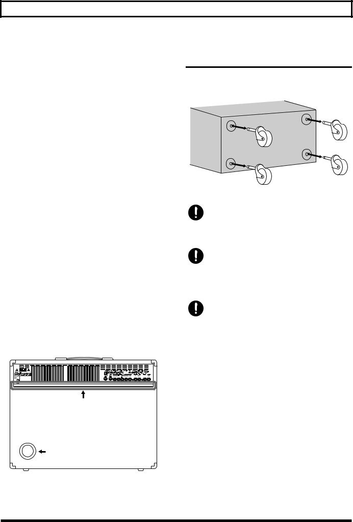
Attaching and Removing the
Casters
Attaching all of the casters can make it easier to move the amplifier.
When using casters, take care not to allow fingers or other parts of the hand or body to get pinched or injured.
Be sure to remove all casters when accidental movement may be dangerous such as when setting up the VGA-7 on stage or when transporting it in a vehicle.
If casters have been attached to the amp, make sure it is used only on a stable, level surface.
9

Basic Opration
* For details on each function, refer to p. 14 and following.
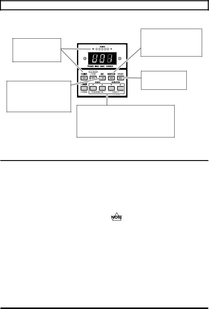
fig.01-1
Manual Button
By pressing the Manual button, you can play using the sound of the current knob settings, as on a conventional guitar amplifier.
GK IN
Use the special cable to connect the GK-2A-compatible guitar (or the guitar in which the GK-2A is installed).
When the GK cable is connected or disconnected, the indicators of the COSM guitar section will blink.
You can use all functions of the COSM guitar, COSM amplifier, and EFFECTS.
Power Switch
Turns the power on/off.
INPUT Jacks
Connect a conventional guitar.
You can use the functions of the
COSM amplifier and EFFECTS.
Effect On/Off Buttons
Switch the effects on/off.
When on, the button indicator will light.
Function select buttons
Press a button to select the desired function.
10
Basic Opration
VARIATION Function
In addition to the settings, there are several other choices of COSM guitar type and tuning, COSM amplifier and speaker, and
EFFECTS delay, chorus and reverb.
* is printed top or under buttons (that the arrow in the picture below should indicate) for which variation settings (types) are provided.
The plate on the upper left of the cabinet provides a list of variations.
Selecting variations
1.Press the button that “  ” is printed, then preselect the variation setting to which you want to change.
2.Press [VARIATION/EDIT], getting its indicator to light. The indicator of the currently selected type will blink.
2,4
2 3
*You can switch the variation setting to the one you want by pressing [PARAMETER ▼/▲].
3.Press [SELECT/VALUE ▼/▲] to select the variation number.
4.Once you’ve selected a variation number, press [VARIATION] again, extinguishing its indicator. The indicator of the currently selected type will light, thus finalizing your selection of a variation.
If you want to save the selected variation, carry out the Write operation. (p. 24)
11
Basic Opration
TUNER Function
Allows you to tune your guitar.
GK setting
These settings are made for a guitar on which the GK-2A is installed, or for a GK-2A-compatible guitar that is to be connected to GK IN.
System setting
Allows settings for tuner, noise suppressor, foot switch, expression pedal, and MIDI to be made.
WRITE
Use this to store settings.
PROGRAM Function
The VGA-7 contains 80 preset patches and 80 user patches.
Use [BANK ▼/▲] and [NUMBER ▼/▲] to select the desired patch.
Preparations for using the VGA-7
Attaching the GK-2A to your guitar
First, attach the GK-2A divided pickup (sold separately) to your guitar.
To learn how, refer to the owner’s manual for the GK-2A.
The GK-2A cannot be used with the following types of guitar.
(When attached to one of these guitars, the
GK-2A will not function correctly.)
•Guitars with unconventional string structures, such as twelve-string guitars or pedal steel guitars
•Guitars that use nylon or gut strings
•Bass guitars
•Other guitars that, for structural reasons, have no location where the GK-2A divided pickup can be attached correctly
About the GK-2A select switch
SYNTH: Select this if you are using a GK-2A divided pickup
MIX: When combining the GK-2A divided pickup with the normal pickup of the guitar
GUITAR: When using the normal pickup of the guitar
If you won’t be connecting the jack of the guitar to the normal guitar input jack of the GK-2A, make sure to set the GK-2A select switch to the SYNTH position.
If this is set to MIX or GUITAR, noise or hum may occur.
About the SYNTH VOL knob of the GK-2A
This controls the volume of the COSM guitar.
12

Making Connections
You will need a guitar on which the GK-2A has been installed, or a GK compatible guitar.
The following equipment will add additional functionality to your VGA-7 system.
•MIDI Foot Controller (sold separately: Roland FC-200)
•Expression Pedal (sold separately: Roland EV-5, BOSS FV-300L)
•Foot Switch (sold separately: BOSS FS-5U/FS-5L)
fig.03
*Use only the specified expression pedal (EV-5 or BOSS FV300L; sold separately). By connecting any other expression pedals, you risk causing malfunction and/or damage to the unit.
*Use an FS-5U (momentary type) foot switch to change program numbers.
After you have prepared your guitar — by installing the GK2A — connect your equipment as shown in the following diagram.
*To prevent malfunction and/or damage to speakers or other devices, always turn down the volume, and turn off the power on all devices before making any connections.
Guitar with GK-2A
or other GK-2A
compatible guitar
MIDI Sequencer etc.
MIDI Foot Controller
(FC-200 etc.)
External Sound Module |
Mixer |
(Guitar synthesizer etc.) |
|
Stereo
Headphones
Conventional
Guitar
Expression Pedal
(Roland EV-5,
BOSS FV-300L etc.)
Foot Switch (BOSS FS-5U/FS-5L etc.)
* When using the FS-5L, only effect on/off can be controlled. (p. 36)
Turning the Power On and Off
Once the connections have been completed, turn on power to your various devices in the order specified. By turning on devices in the wrong order, you risk causing malfunction and/or damage to speakers and other devices.
External devices (except for output devices) → VGA-7→ output devices
*When the power is turned on, the last-selected patch number or Manual mode (p. 24) will be selected.
*When this device is in operation, the cooling fins located on the rear panel will become hot. Take care not to touch them with your hands.
*This unit is equipped with a protection circuit. A brief interval after power up is required before the unit will operate normally.
*Turn the volume down before you turn the power on or off. Even if the volume is turned down, some extraneous sound may be heard when turning the power on/off, but this is not a malfunction.
13
Make settings for the divided pickup
The sound quality of the VGA-7 is dramatically affected by how the divided pickup is installed. In order to minimize tonal irregularity due to variations in installation, you must input the manner in which the divided pickup is installed (divided pickup settings).
When playing the VGA-7, divided pickup settings are extremely important to the final sound quality. You must be sure to set these parameters correctly.
Redo the settings when you change the guitar you are using.
To make settings for the divided pickup, press [GK], getting the indicator to light, and then make the
necessary settings.
fig.04-1
When you are finished, press [GK] once again, extinguishing its indicator.
*Once you have made the correct settings, they will be saved even when the power is turned off.
You do not need to redo these settings each time you play.
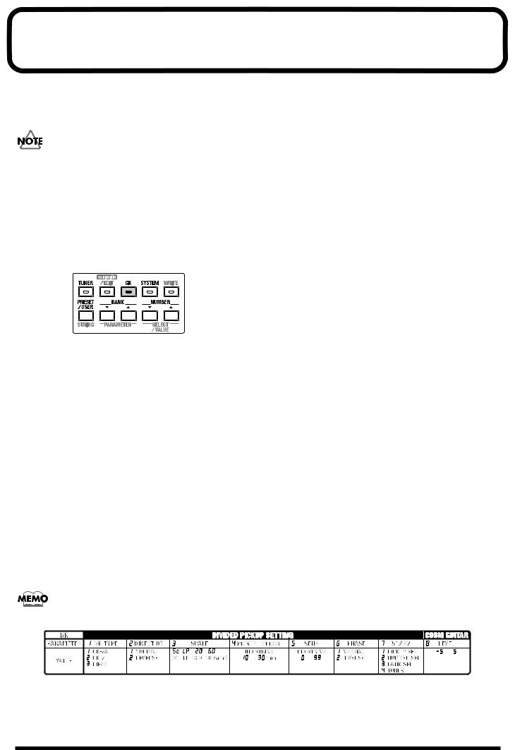
When you press [GK], the VGA-7 will be set as follows, so that the sound will be most appropriate for the divided pickup settings.
*Although you will still be able to adjust the volume—using either [VOLUME] on the COSM guitar or [MASTER]—all other buttons and knobs on the panel will be disabled.
COSM GUITAR
TYPE: |
ST (Variation 1) |
PICKUP: |
C |
TUNING: |
NORMAL |
CAPO: |
Off |
COSM AMPLIFIER
TYPE: |
CLEAN (Variation 1) |
GAIN: |
50 |
EQUALIZER |
|
(BASS/MIDDLE/TREBLE): |
50 |
PRESENCE: |
50 |
SPEAKER: |
ORIGINAL |
EFFECTS
EFX: |
Off |
DELAY: |
Off |
CHORUS: |
Off |
REVERB: |
Off |
A list of divided pickup settings is provided on the plate located on the upper right of the cabinet.
fig.80
14
Make settings for the divided pickup
Specify the pickup type (1 GK TYPE)
* With the factory settings, this is set to “1 GK-2A.”
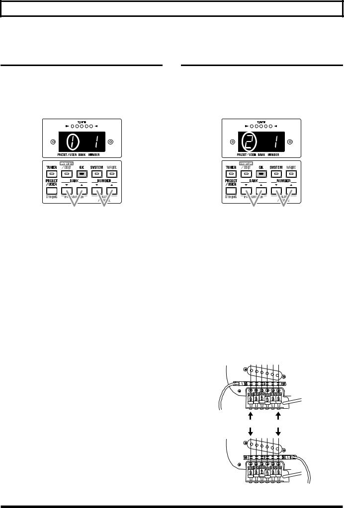
1.Press [PARAMETER ▼/▲] until “1” is shown (blink) at the left side of the display.
This selects “1 GK TYPE.”
Specify the direction in which the pickup is attached (2 DIRECTION)
* With the factory settings, this is set to “1 NORMAL.”
1.Press [PARAMETER ▼/▲] until “2” is shown (blink) at the left of the display.
This selects “2 DIRECTION.”
12
2.Press [SELECT/VALUE ▼/▲] to select the desired pickup type.
The corresponding number will appear in the right of the display.
* The example display shows that “1 GK-2A” has been selected.
Display |
|
Setting |
|
|
|
|
|
|
1 |
GK-2A: |
Make this setting if you are |
|
|
using a GK-2A. |
|
|
|
2 |
GK-2: |
Make this setting if you are |
|
|
using a GK-2. |
|
|
|
3 |
PIEZO: |
Make this setting if you are |
|
|
using a piezo divided pickup. |
|
|
|
*A piezo-type pickup uses a piezo-electric sensor attached to the bridge of the guitar to detect the vibrations of the strings.
12
2.Press [SELECT/VALUE ▼/▲] to select the direction in which the divided pickup is installed.
The corresponding number will appear in the right of the display.
*The example display shows that “1 NORMAL” has been selected.
Display |
|
|
Setting |
|
|
|
|
|
|
|
|
1 |
|
NORMAL: |
In this direction, the cable |
|
|
|
exits on the side of string 6. |
|
|
|
|
2 |
|
REVERSE: |
In this direction, the cable |
|
|
|
exits on the side of string 1. |
|
|
|
|
|
NORMAL |
|
|
string 6 |
string 1 |
REVERSE
15

Make settings for the divided pickup
Specify the scale length (3 SCALE)
* With the factory settings, this is set to “
 .”
.”
When playing the VGA-7, the scale length setting is extremely important to the final sound quality.
You must be sure to set this parameter correctly.
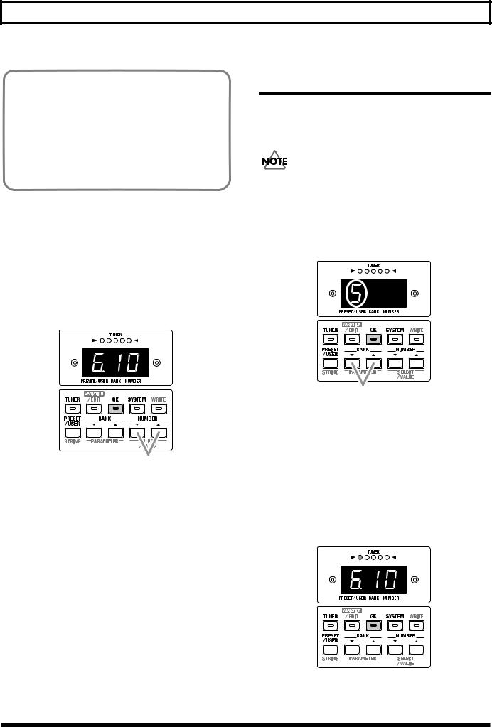
1.Press [PARAMETER ▼/▲] until “3” is shown (blink) at the left of the display.
This selects “3 SCALE.”
12
2.Press [SELECT/VALUE ▼/▲] to set the scale length.
In the display, select the scale length (the length from the bridge to the nut) that is closest to your guitar.
Display |
Setting |
ST type guitars (648 mm)
LP type guitars (628 mm)
20–60 620 mm–660 mm
Set the length from the pickup to the bridge (4 PICKUP-BRIDGE)
* This setting is unnecessary if a piezo pickup has been selected.
Use a ruler or tape measure to actually measure along each string from the center of the divided pickup to the bridge. Specify the result as the length in millimeters for each string.
string 6 |
string 1 |
String
|
|
Pickup |
Bridge |
|
|
|
* The factory settings are shown in the following. |
|
|||||
String |
1 |
2 |
3 |
4 |
5 |
6 |
Length (mm) |
18 |
19 |
20 |
19 |
20 |
21 |
1.Press [PARAMETER ▼/▲] until “4” is shown (blink) at the left of the display.
This selects “4 PICKUP-BRIDGE.”
1
2.Play any string on your guitar.
The string that you played will be detected automatically, and the string number will be shown in the display.
16
Make settings for the divided pickup
You can press [STRING] to specify the string number directly.
Each press of the button takes you to the next string number, from string 1 through string 6.
(The string number is indicated by a dot.)
If you play a string other than the one indicated by the dot, the display switches to the number of the string that was played.
3.Use [SELECT/VALUE ▼/▲] to specify the distance for the selected string number.
Display |
Setting |
|
|
|
|
10–30 |
10–30 mm |
|
|
*The example display shows that the 6th string is at a distance of 10 mm.
Adjusting the Pickup Sensitivity for Each String (5 SENS)
Adjust the pickup sensitivity for each string according to how the GK-2A divided pickup was installed.
* With the factory settings, this is set to “65.”
Make sure to set the divided pickup select switch to the
“SYNTH” position.
1.Press [PARAMETER ▼/▲] until “5” is shown (blink) at the left of the display.
This selects “5 SENS.”
3
4. Repeat steps 2–3 for each of the remaining strings.
1
2.Play any string on your guitar.
The string you played will be detected automatically, and the string number will appear in the display.
At the same time, the TUNER indicator will show the level. The indicators will light from left to right, corresponding to the strength with which you played the string.
*If you play the string too week or the pickup sensitivity is set too low, the string number may not appear in the display.
17
 Loading...