


Reference Manual
© 2017 Roland Corporation |
01 |

Panel Descriptions
Rubix22
Front Panel
2 |
3 |
2 |
6 |
8 |
4 |
5 |
9 |
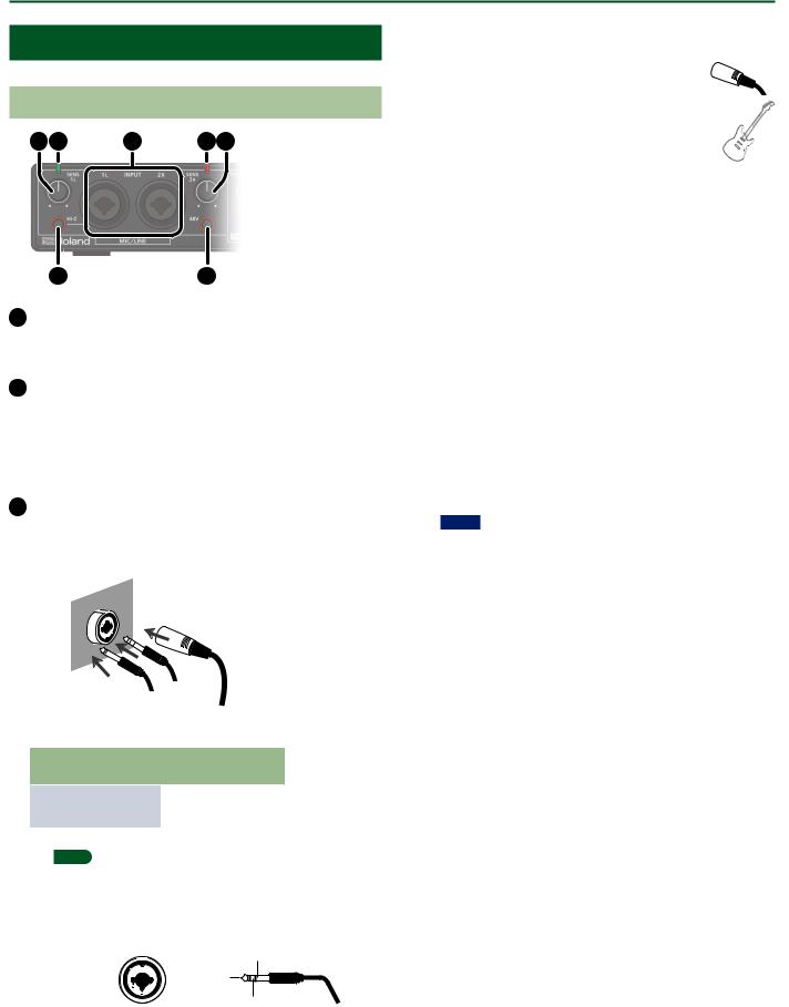
1 [SENS 1L] knob, [SENS 2R] knob
Adjust the volume of the audio signal that is input via the INPUT (1L, 2R) jacks.
2 Level indicator
The indicator is lit green if an audio signal greater than -24 dB (*) is being input to the INPUT (1L, 2R) jacks. If the input level is -3 dB (*) or higher, the indicator is lit red. If the indicator is lit red, use the [SENS 1L] knob and [SENS 2R] knob to adjust the input level.
* The level relative to the maximum allowable input (0 dB)
3 INPUT (1L, 2R) connectors (combo jacks)
These are analog audio input jacks with microphone preamps. They accommodate both XLR connectors and 1/4-inch phone type jacks, and support both balanced and unbalanced connections.
XLR connector (balanced)
Phone |
type plug |
|
TRS phone |
|
|
type plug |
|||
|
(unbalanced) |
|
||
|
(balanced) |
|||
|
|
|||
|
|
|
||
INPUT (1L, 2R) |
Input sensitivity |
|||
connectors |
||||
|
|
|||
|
|
|||
|
|
|||
XLR connector |
-60– -12dBu |
|||
|
|
|||
Phone type plug |
-44–+4dBu |
|||
|
|
|
|
|
MEMO
55 To prevent malfunction and equipment failure, always turn down the volume, and turn off all the units before making any connections.
55 Pin assignment of INPUT connector/jack
1: GND |
GND (SLEEVE) |
|
HOT (TIP) |
||
2: HOT |
||
3: COLD |
COLD (RING) |
|
|
55 Set the [Hi-Z] button (p. 2) and [48V] button (p. 2) as appropriate for the audio device that is connected.
55 Use a microphone with an XLR connector. The sound level will be very low if you use a microphone with a phone type plug.
55 Whenconnectingaguitarorbass,usetheINPUT1L jack. The sound level will be very low if you connect directly to the INPUT 2R jack.
4 [Hi-Z] button
Determines the impedance of the INPUT 1L jack.
You can select high impedance (Hi-Z) or low impedance (Lo-Z) as appropriate for the connected equipment.
[Hi-Z] button |
Equipment connected to the INPUT 1L jack |
|
|
|
|
Lit (Hi-Z) |
Guitar or bass |
|
|
Unlit (Lo-Z) |
Other equipment (such as synthesizers) |
|
|
5 [48V] button
Determines whether the Rubix22 supplies phantom power to the XLR connectors of the INPUT (1L, 2R) jacks.
[48V] button |
Connected equipment |
|
|
|
|
|
|
|
|
Condenser microphone that requires phantom |
|
Lit |
power |
|
* Phantom power supplied by this unit: DC 48 V; |
||
|
||
|
maximum 6 mA. (current value per channel) |
|
|
|
|
Unlit |
Other equipment |
|
|
|
NOTE
55 You must leave the [48V] button set to “OFF” unless condenser microphones requiring phantom power are connected to the XLR connectors. Supplying phantom power to a dynamic microphone or to an audio playback device may damage the equipment. For details on the requirements of your microphone, refer to its owner’s manual.
55 Minimize the volume before you turn phantom power on or off. Even if the volume is minimized, turning phantom power on/off might make a sound, but this is not a malfunction.
6 Power indicator
Indicates the status of the connection with a USB device.
Power |
Status |
|
indicator |
||
|
||
|
|
Lit |
Connected to a computer or iPad. |
|
|
Unlit |
Not connected to a computer or iPad. |
|
|
7 [OUTPUT] knob
Adjusts the output level of the audio signal.
MEMO
Adjusting the [OUTPUT] knob does not change the volume that is output to the Q (headphones) jack.
8 [Q] (Headphone) knob
Adjusts the output level of the Q jack.
9 Q(Headphone) jack
Used to connect headphones.
MEMO
This jack outputs the same sound as the OUTPUT (1L, 2R) jacks. Even if headphones are connected, sound will be output from the OUTPUT (1L, 2R) jacks.
2

Panel Descriptions
Rear Panel
1 |
2 |
3 |
4 |
5 |
6 |
7 |
1 5V DC connector
Connect this to a commercially available USB AC adaptor.
About the USB AC adaptor
Read the section on “Using the Unit Safely” in the manual included with your USB AC adaptor. Use a USB AC adaptor that meets the following specifications.
55 USB micro-B type
55 Output voltage: 4.8–5.2 V
55 Output current: 500 mA (0.5A) or higher
We have verified that the Rubix operates with typical USB AC adaptors that meet the above conditions, but cannot guarantee that it will work with all adaptors that meet these conditions.
Be aware that even under identical conditions, differences in the design specifications of a USB AC adaptor and differences in the conditions of use might make the Rubix operate or perform differently.
2 [POWER SOURCE] switch
Selects the connector from which power is obtained.
Switch |
Connector from which power is obtained |
|||
position |
||||
|
||||
|
|
|
|
|
|
|
|
|
|
|
|
|
5V DC connector (A commercially available USB |
|
|
|
|
adaptor is required.) |
|
|
|
|
|
|
|
|
|
USB port (Power is supplied from the connected |
|
|
|
|
computer.) |
|
|
|
|
|
|
3 USB port ( |
) |
Connects to the computer.
4 MIDI (OUT, IN) connectors
Connect the MIDI OUT connector to an external MIDI sound module, etc.
Connect the MIDI IN connector to a MIDI keyboard or MIDI controller.
5 [DIRECT MONITOR] switch
Determines whether the audio signals input via the INPUT (1L, 2R) are output directly.
Switch |
Explanation |
|
position |
||
|
||
|
|
MONO |
Monitor in mono. |
|
|
STEREO |
Monitor in stereo. |
|
|
OFF |
Select when monitoring using the DAW |
software. Only audio input via the Rubix22’s USB |
|
|
port can be monitored. |
|
|
MEMO
55 When a guitar or microphone is connected to the INPUT 1L jack and nothing is connected to the INPUT 2R jack, set to
“MONO.”
55 Even when set to “MONO,” a stereo audio signal is output from the Rubix22’s USB port.
6 [GROUND LIFT] switch
Normally, this switch should be set to “NOR” (NORMAL).
If ground loop noise occurs, switching this to “LIFT” might eliminate the noise.
MEMO
OUTPUT (1L, 2R) jacks (balanced TRS type)

 NOR
NOR
LIFT
55 The GND (SLEEVE) of the OUTPUT (1L, 2R) jacks (TRS balanced type) is disconnected from ground.
55 In some cases, there might be no sound if you connect a balanced cable to an unbalanced device and set this switch to the “LIFT” position. If so, set the switch to “NOR.”
7 OUTPUT (1L, 2R) jacks (balanced TRS type)
Output the analog audio signal.
MEMO
55 Pin assignment of OUTPUT jack GND (SLEEVE)
HOT (TIP)
COLD (RING)
55 The wiring of this device uses “impedance balancing.” The audio signal is conveyed via HOT and GND in unbalanced form, but since COLD and GND are connected by a resistor, the electrical circuit is balanced. This provides the same noise-reducing effect as a balanced circuit.
3
Panel Descriptions
Rubix24
Front Panel
2 |
3 |
2 |
4 |
5 |
1 [SENS 1L] knob, [SENS 2R] knob
Adjust the volume of the audio signal that is input via the INPUT (1L, 2R) jacks.
2 Level indicator
The indicator is lit green if an audio signal greater than -24 dB (*) is being input to the INPUT (1L, 2R) jacks. If the input level is -3 dB (*) or higher, the indicator is lit red. If the indicator is lit red, use the [SENS 1L] knob and [SENS 2R] knob to adjust the input level.
* The level relative to the maximum allowable input (0 dB)
3 INPUT (1L, 2R) connectors (combo jacks)
These are analog audio input jacks with microphone preamps. They accommodate both XLR connectors and 1/4-inch phone type jacks, and support both balanced and unbalanced connections.
XLR connector (balanced)
Phone |
type plug |
|
TRS phone |
|
|
type plug |
|||
|
(unbalanced) |
|
||
|
(balanced) |
|||
|
|
|||
|
|
|
||
INPUT (1L, 2R) |
Input sensitivity |
|||
connectors |
||||
|
|
|||
|
|
|||
|
|
|||
XLR connector |
-60– -12dBu |
|||
|
|
|||
Phone type plug |
-44–+4dBu |
|||
|
|
|
|
|
MEMO
55 To prevent malfunction and equipment failure, always turn down the volume, and turn off all the units before making any connections.
55 Pin assignment of INPUT connector/jack
1: GND |
GND (SLEEVE) |
|
HOT (TIP) |
||
2: HOT |
||
3: COLD |
COLD (RING) |
|
|
55 Set the [Hi-Z] button (p. 4) and [48V] button (p. 4) as appropriate for the audio device that is connected.
55 Use a microphone with an XLR connector.
The sound level will be very low if you use a microphone with a phone type plug.
55 When connecting a guitar or bass, use the INPUT 1L jack. The sound level will be very low if you connect directly to the INPUT 2R jack.
4 [Hi-Z] button
Determines the impedance of the INPUT 1L jack.
You can select high impedance (Hi-Z) or low impedance (Lo-Z) as appropriate for the connected equipment.
[Hi-Z] button |
Equipment connected to the INPUT 1L jack |
|
|
|
|
Lit (Hi-Z) |
Guitar or bass |
|
|
Unlit (Lo-Z) |
Other equipment (such as synthesizers) |
|
|
5 [48V] button
Determines whether the Rubix24 supplies phantom power to the XLR connectors of the INPUT (1L, 2R) jacks.
[48V] button |
Connected equipment |
|
|
|
|
|
|
|
|
Condenser microphone that requires phantom |
|
Lit |
power |
|
* Phantom power supplied by this unit: DC 48 V; |
||
|
||
|
maximum 6 mA. (current value per channel) |
|
|
|
|
Unlit |
Other equipment |
|
|
|
NOTE
55 You must leave the [48V] button set to “OFF” unless condenser microphones requiring phantom power are connected to the XLR connectors. Supplying phantom power to a dynamic microphone or to an audio playback device may damage the equipment. For details on the requirements of your microphone, refer to its owner’s manual.
55 Minimize the volume before you turn phantom power on or off. Even if the volume is minimized, turning phantom power on/off might make a sound, but this is not a malfunction.
4

Panel Descriptions
6 7 |
9 11 |
13 |
11 Power indicator |
Indicates the status of the connection with a USB device.
Power |
Status |
|
indicator |
||
|
||
|
|
Lit |
Connected to a computer or iPad. |
|
|
Unlit |
Not connected to a computer or iPad. |
|
|
8 |
10 |
14 |
12 [OUTPUT] knob
6 Reduction indicator
If the [COMP/LIMIT] button is turned on, this indicator is lit red when the audio input signal exceeds the level specified by the [THRS] knob.
7 [THRS] knob
Specifies the level at which the compressor or limiter will begin operating. As you turn this knob toward the right, the compressor or limiter will be applied more deeply, producing a thicker sound.
8 [COMP/LIMIT] button
Turns the compressor/limiter on/off.
9 [DIRECT MONITOR] knob
Adjusts the balance of the audio signal that is output to the PHONES jack and the OUTPUT (1L, 2R) jacks.
Balance
Adjusts the output level of the audio signal.
MEMO
Adjusting the [OUTPUT] knob does not change the volume that is output to the Q (headphones) jack or the OUTPUT (3L, 4R) jacks.
13 [Q] (Headphone) knob
Adjusts the output level of the Q jack.
14 Q(Headphone) jack
Used to connect headphones.
The audio signal selected by the [PHONES SOURCE] switch is output.
MEMO
Even if headphones are connected, sound will be output from the OUTPUT (1L, 2R) and OUTPUT (3L, 4R) jacks.
100% |
INPUT |
0% |
100%
PLAYBACK
0%
The audio signal of the computer that is connected to the USB port is output.
The audio signal that is input to the INPUT (1L, 2R) jacks is output.
If you’re using soft monitoring on your DAW, set this to
“PLAYBACK.” MEMO
Sometimes you might hear noise when turning this knob, but this is not a malfunction.
10 [MONO] button
If this is turned on, the audio signal that is input to the INPUT (1L, 2R) jacks is monitored in mono.
MEMO
55 When a guitar or microphone is connected to the INPUT 1L jack and nothing is connected to the INPUT 2R jack, set the
[MONO] button to “ON.”
55 Even when set to “MONO,” a stereo audio signal is output from the Rubix24’s USB port.
5
Panel Descriptions
Rear Panel
1 |
2 |
3 |
4 |
5 |
1 5V DC connector
Connect this to a commercially available USB AC adaptor.
About the USB AC adaptor
Read the section on “Using the Unit Safely” in the manual included with your USB AC adaptor. Use a USB AC adaptor that meets the following specifications.
55 USB micro-B type
55 Output voltage: 4.8–5.2 V
55 Output current: 1 A or higher
We have verified that the Rubix operates with typical USB AC adaptors that meet the above conditions, but cannot guarantee that it will work with all adaptors that meet these conditions.
Be aware that even under identical conditions, differences in the design specifications of a USB AC adaptor and differences in the conditions of use might make the Rubix operate or perform differently.
2 [POWER SOURCE] switch
Selects the connector from which power is obtained.
Switch |
Connector from which power is obtained |
|||
position |
||||
|
||||
|
|
|
|
|
|
|
|
|
|
|
|
|
5V DC connector (A commercially available USB |
|
|
|
|
adaptor is required.) |
|
|
|
|
|
|
|
|
|
USB port (Power is supplied from the connected |
|
|
|
|
computer.) |
|
|
|
|
|
|
3 USB port |
) |
Connects to the computer.
4 MIDI (OUT, IN) connectors
Connect the MIDI OUT connector to an external MIDI sound module, etc.
Connect the MIDI IN connector to a MIDI keyboard or MIDI controller.
6 |
9 |
5 OUTPUT (1L, 2R, 3L, 4R) jacks (balanced TRS type)
Output the analog audio signal.
MEMO
55 Pin assignment of OUTPUT jack GND (SLEEVE)
HOT (TIP)
COLD (RING)
55 The wiring of this device uses “impedance balancing.” The audio signal is conveyed via HOT and GND in unbalanced form, but since COLD and GND are connected by a resistor, the electrical circuit is balanced. This provides the same noise-reducing effect as a balanced circuit.
6 [GROUND LIFT] switch
Normally, this switch should be set to “NOR” (NORMAL).
If ground loop noise occurs, switching this to “LIFT” might eliminate the noise.
MEMO
OUTPUT (1L, 2R, 3L, 4R) jacks (balanced TRS type)

 NOR
NOR
LIFT
55 The GND (SLEEVE) of the OUTPUT (1L, 2R, 3L, 4R) jacks (TRS balanced type) is disconnected from ground.
55 In some cases, there might be no sound if you connect a balanced cable to an unbalanced device and set this switch to the “LIFT” position. If so, set the switch to “NOR.”
7 [LOOPBACK] switch
If this is turned on, the audio signal that is input to the
INPUT (1L, 2R) jacks is mixed with the audio signal played back from the computer, and this mixed signal is then sent back (returned) to the computer. You can use this for live broadcasting to the internet.
MEMO
If you intend to turn the [LOOPBACK] switch on, you should turn off your DAW software’s monitor function and the monitoring function of Windows. Failing to do this will cause oscillation (feedback) or doubling of the input sound.
8 [COMP/LIMIT TYPE] switch
Switches the response of the built-in compressor/limiter circuit (p. 19).
9 [PHONES SOURCE] switch
Selects the audio signal that is monitored in headphones.
Switch |
Explanation |
|
position |
||
|
||
|
|
1/2 |
Monitor the output of OUTPUT (1L, 2R). |
|
|
3/4 |
Monitor the output of OUTPUT (3L, 4R). |
|
|
6
Panel Descriptions
Rubix44
Front Panel
MEMO
The following explanation and illustration covers the INPUT (1L, 2R) jack section. The Rubix44 additionally has INPUT (3L, 4R) jacks with placement and functionality that are equivalent to the INPUT (1L, 2R) jacks. This explanation
in |
way |
|
|
(3L, 4R) jack section. |
2 |
3 |
2 |
6 |
7 |
4 |
5 |
8 |
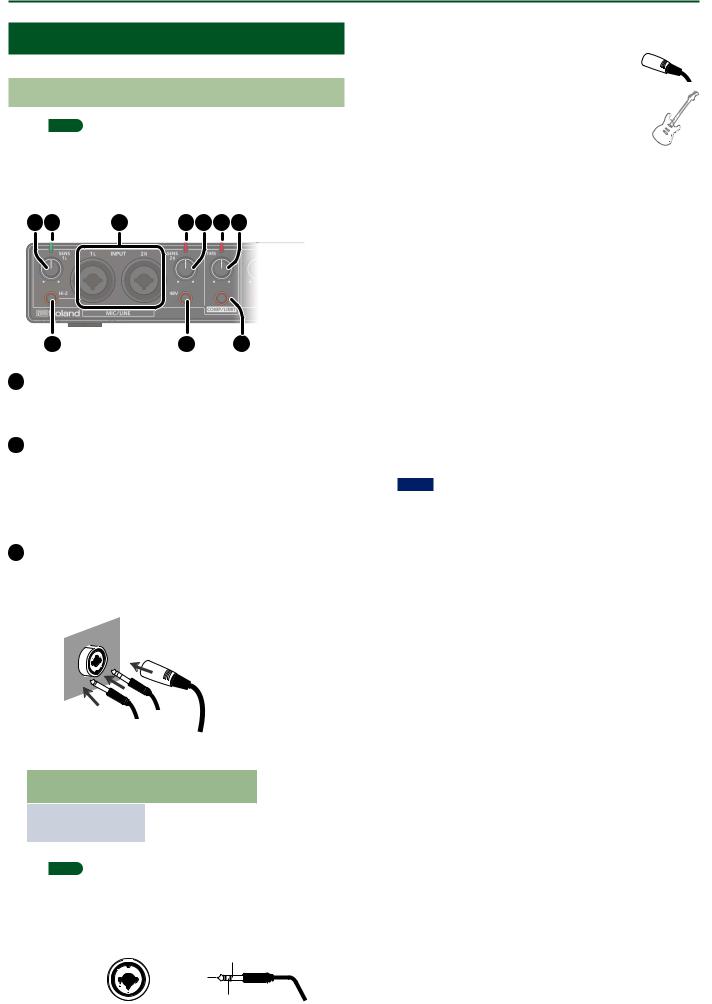
1 [SENS 1L] knob, [SENS 2R] knob
Adjust the volume of the audio signal that is input via the INPUT (1L, 2R) jacks.
2 Level indicator
The indicator is lit green if an audio signal greater than -24 dB (*) is being input to the INPUT (1L, 2R) jacks. If the input level is -3 dB (*) or higher, the indicator is lit red. If the indicator is lit red, use the [SENS 1L] knob and [SENS 2R] knob to adjust the input level.
* The level relative to the maximum allowable input (0 dB)
3 INPUT (1L, 2R) connectors (combo jacks)
These are analog audio input jacks with microphone preamps. They accommodate both XLR connectors and 1/4-inch phone type jacks, and support both balanced and unbalanced connections.
XLR connector (balanced)
Phone |
type plug |
|
TRS phone |
|
|
type plug |
|||
|
(unbalanced) |
|
||
|
(balanced) |
|||
|
|
|||
|
|
|
||
INPUT (1L, 2R) |
Input sensitivity |
|||
connectors |
||||
|
|
|||
|
|
|||
|
|
|||
XLR connector |
-60– -12dBu |
|||
|
|
|||
Phone type plug |
-44–+4dBu |
|||
|
|
|
|
|
MEMO
55 To prevent malfunction and equipment failure, always turn down the volume, and turn off all the units before making any connections.
55 Pin assignment of INPUT connector/jack
1: GND |
GND (SLEEVE) |
|
HOT (TIP) |
||
2: HOT |
||
3: COLD |
COLD (RING) |
|
|
55 Set the [Hi-Z] button (p. 7) and [48V] button (p. 7) as appropriate for the audio device that is connected
55 Use a microphone with an XLR connector.
The sound level will be very low if you use a microphone with a phone type plug.
55 Whenconnectingaguitarorbass,usetheINPUT1L or INPUT 3L jack. The sound level will be very low if you connect directly to the INPUT 2R or INPUT 4R jack.
4 [Hi-Z] button
Determines the impedance of the INPUT 1L jack.
You can select high impedance (Hi-Z) or low impedance (Lo-Z) as appropriate for the connected equipment.
[Hi-Z] button |
Equipment connected to the INPUT 1L jack |
|
|
|
|
Lit (Hi-Z) |
Guitar or bass |
|
|
Unlit (Lo-Z) |
Other equipment (such as synthesizers) |
|
|
5 [48V] button
Determines whether the Rubix44 supplies phantom power to the XLR connectors of the INPUT (1L, 2R) jacks.
[48V] button |
Connected equipment |
|
|
|
|
|
|
|
|
Condenser microphone that requires phantom |
|
Lit |
power |
|
* Phantom power supplied by this unit: DC 48 V; |
||
|
||
|
maximum 6 mA. (current value per channel) |
|
|
|
|
Unlit |
Other equipment |
|
|
|
NOTE
55 You must leave the [48V] button set to “OFF” unless condenser microphones requiring phantom power are connected to the XLR connectors. Supplying phantom power to a dynamic microphone or to an audio playback device may damage the equipment. For details on the requirements of your microphone, refer to its owner’s manual.
55 Minimize the volume before you turn phantom power on or off. Even if the volume is minimized, turning phantom power on/off might make a sound, but this is not a malfunction.
6 Reduction indicator
If the [COMP/LIMIT] button is turned on, this indicator is lit red when the audio input signal exceeds the level specified by the [THRS] knob.
7 [THRS] knob
Specifies the level at which the compressor or limiter will begin operating. As you turn this knob toward the right, the compressor or limiter will be applied more deeply, producing a thicker sound.
8 [COMP/LIMIT] button
Turns the compressor/limiter on/off.
7

Panel Descriptions
9 |
11 12 |
13 |
10 |
14 |
9 DIRECT MONITOR [1/2], [3/4] knobs
11 Power indicator
Indicates the status of the connection with a USB device.
Power |
Status |
|
indicator |
||
|
||
|
|
Lit |
Connected to a computer or iPad. |
|
|
Unlit |
Not connected to a computer or iPad. |
|
|
Rapid |
The power will soon be turned off automatically |
blinking |
by the auto power off function. |
|
|
MEMO
Adjust the balance at which the audio signals that are input to the INPUT (1L, 2R) jacks and INPUT (3L, 4R) jacks are output to OUTPUT (1L, 2R).
When using soft monitoring on your DAW, turn these knobs all the way to the left.
|
Output balance |
|
||
|
|
100% |
|
|
INPUT (1L, 2R) |
|
|
INPUT (3L, 4R) |
|
|
0% |
|
||
|
|
|
|
|
MEMO
Sometimes you might hear noise when turning this knob, but this is not a malfunction.
10 [MONO] button
If this is turned on, the audio signal that is input to the INPUT (1L, 2R) jacks (or INPUT (3L, 4R) jacks) is monitored in mono.
MEMO
55 When a guitar or microphone is connected to the INPUT 1L jack and nothing is connected to the INPUT 2R jack, set the
[MONO] button to “ON.”
55 Even when set to “MONO,” a stereo audio signal is output from the Rubix44’s USB port.
This unit automatically powers-off in the following conditions (Auto Off function).
55 The unit is not connected to a computer or tablet 55 There has been no audio input for 10 hours
Five minutes before the power turns off automatically, the power indicator blinks rapidly. After the unit switches off, turn the power on if you want to use the Rubix44 again.
12 [OUTPUT] knob
Adjusts the output level of the audio signal.
MEMO
Adjusting the [OUTPUT] knob does not change the volume that is output to the Q (headphones) jack or the OUTPUT (3L, 4R) jacks.
13 [Q] (Headphone) knob
Adjusts the output level of the Q jack.
14 Q(Headphone) jack
Used to connect headphones.
The audio signal selected by the [PHONES SOURCE] switch is output.
MEMO
Even if headphones are connected, sound will be output from the OUTPUT (1L, 2R) jacks.
8

Panel Descriptions
Rear Panel
3 |
4 |
5 |
1 DC IN jack
Connect the included AC adaptor here.
2 Ground terminal
Depending on the circumstances of a particular setup, you may experience a discomforting sensation, or perceive that the surface feels gritty to the touch when you touch this device, microphones connected to it, or the metal portions of other objects, such as guitars. This is due to an infinitesimal electrical charge, which is absolutely harmless. However, if you are concerned about this, connect the ground terminal with an external ground. When
the unit is grounded, a slight hum may occur, depending on the particulars of your installation. If you are unsure of the connection method, contact the nearest Roland Service Center, or an authorized Roland distributor, as listed on the “Information” page.
* Unsuitable places for connection
55 Water pipes (may result in shock or electrocution) 55 Gas pipes (may result in fire or explosion)
55 Telephone-line ground or lightning rod (may be dangerous in the event of lightning)
3 [POWER] switch
Turns the power of the Rubix on/off.
Concerning the Auto Off function
This unit automatically powers-off in the following conditions (Auto Off function).
55 The unit is not connected to a computer or tablet 55 There has been no audio input for 10 hours
If you don’t want the unit to power-off automatically, connect it to a computer or tablet.
4 USB port ( |
) |
Connects to the computer.
MEMO
The Rubix44 cannot be powered via its USB port (it will not operate).
5 MIDI (OUT, IN) connectors
Connect the MIDI OUT connector to an external MIDI sound module, etc.
Connect the MIDI IN connector to a MIDI keyboard or MIDI controller.
6 |
8 |
10 |
6 OUTPUT (1L, 2R, 3L, 4R) jacks (balanced TRS type)
Output the analog audio signal.
MEMO
55 Pin assignment of OUTPUT jack GND (SLEEVE)
HOT (TIP)
COLD (RING)
55 The wiring of this device uses “impedance balancing.” The audio signal is conveyed via HOT and GND in unbalanced form, but since COLD and GND are connected by a resistor, the electrical circuit is balanced. This provides the same noise-reducing effect as a balanced circuit.
7 [GROUND LIFT] switch
Normally, this switch should be set to “NOR” (NORMAL).
If ground loop noise occurs, switching this to “LIFT” might eliminate the noise.
MEMO
OUTPUT (1L, 2R, 3L, 4R) jacks (balanced TRS type)

 NOR
NOR
LIFT
55 The GND (SLEEVE) of the OUTPUT (1L, 2R, 3L, 4R) jacks (TRS balanced type) is disconnected from ground.
55 In some cases, there might be no sound if you connect a balanced cable to an unbalanced device and set this switch to the “LIFT” position. If so, set the switch to “NOR.”
8 [PHONES SOURCE] switch
Selects the audio signal that is monitored in headphones.
Switch |
Explanation |
|
position |
||
|
||
|
|
1/2 |
Monitor the output of OUTPUT (1L, 2R). |
|
|
3/4 |
Monitor the output of OUTPUT (3L, 4R). |
|
|
9 [LOOPBACK] switch
If this is turned on, the audio signal that is input to the INPUT (1L, 2R) jacks and INPUT (3L, 4R) jacks is mixed with the audio signal played back from the computer, and this mixed signal is then sent back (returned) to the computer. You can use this for live broadcasting to the internet.
MEMO
If you intend to turn the [LOOPBACK] switch on, you should turn off your DAW software’s monitor function and the monitoring function of Windows. Failing to do this will cause oscillation (feedback) or doubling of the input sound.
10 [COMP/LIMIT TYPE] switch
Switches the response of the built-in compressor/limiter circuit (p. 19).
9

Getting Ready to Use the Rubix
Connecting to a Windows 10 Computer
If you’re using Windows 10, access the following URL to check the latest information.
&http://roland.cm/rubix/
Connecting to a Windows 8.1 / Windows 8 / Windows 7 Computer
If you’re using this product with Windows 8.1, Windows 8, or Windows 7, install the driver
In order to use this product, you must download and install the driver.
For details on installation, refer to ”Installing the USB Driver (Before Using the Product for the First Time)” (p. 10) and “Connecting to a Computer” (p. 11).
NOTE
Install the driver before connecting this product to your computer. If you’ve already connected this product to your computer, temporarily disconnect it before you proceed.
Installing the USB Driver (Before Using the Product for the First Time)
1.With the Rubix22 / Rubix24 / Rubix44 not connected, start up your computer.
2.Download the USB driver from the Roland website, and begin the installation as directed below.
Roland Website
http://roland.cm/rubix/
1. Download the latest
2. Doubleclick this.
3.Follow the on-screen directions to install the USB driver.
NOTE
Don’t connect the Rubix22 / Rubix24 / Rubix44 to your computer until USB driver installation has ended.
MEMO
55 If a Windows security dialog box appears, click the [Install] button.
55 If an “Install software” dialog box appears, click the
[Continue] button.
55 If any other message appears, proceed as directed by the message.
4.As described in “Connecting to a Computer” (p. 11), connect the Rubix22 / Rubix24 / Rubix44 to your computer.
10
 Loading...