


Owner’s Manual
Before using this unit, carefully read the sections entitled: “USING THE UNIT SAFELY”(p. 4) and “IMPORTANT NOTES” (p. 6). These sections provide important information concerning the proper operation of the unit. Additionally, in order to feel assured that you have gained a good grasp of every feature provided by your new unit, owner’s manual should be read in its entirety. The manual should be saved and kept on hand as a convenient reference.
Copyright © 2011 ROLAND CORPORATION
All rights reserved. No part of this publication may be reproduced in any form without the written permission of ROLAND CORPORATION.
*Roland is either registered trademark or trademark of Roland Corporation in the United States and/or other countries.
*All product names mentioned in this document are trademarks or registered trademarks of their respective owners.

For the U.K.
IMPORTANT: THE WIRES IN THIS MAINS LEAD ARE COLOURED IN ACCORDANCE WITH THE FOLLOWING CODE.
BLUE: NEUTRAL
BROWN: LIVE
As the colours of the wires in the mains lead of this apparatus may not correspond with the coloured markings identifying the terminals in your plug, proceed as follows:
The wire which is coloured BLUE must be connected to the terminal which is marked with the letter N or coloured BLACK.
The wire which is coloured BROWN must be connected to the terminal which is marked with the letter L or coloured RED. Under no circumstances must either of the above wires be connected to the earth terminal of a three pin plug.
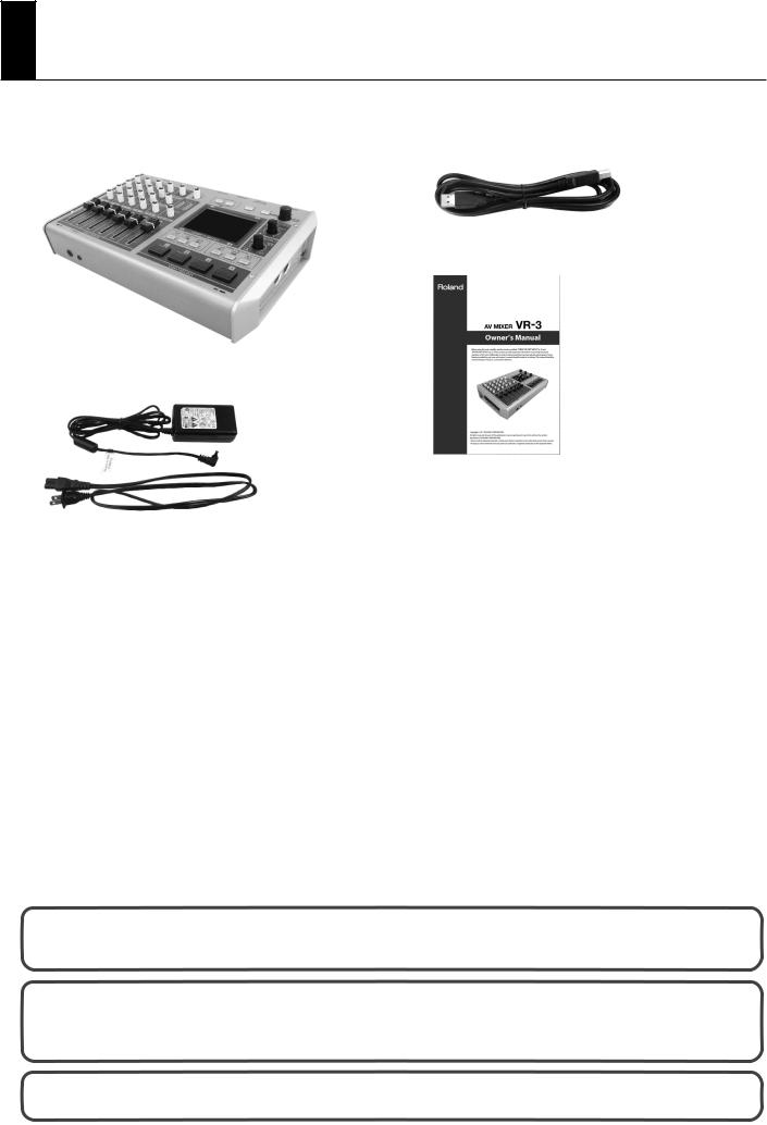
Check the included items
The following items are included. Please make sure that all items are present. If anything is missing, please contact your dealer.
VR-3 itself |
USB cable (A type - B type) |
Owner’s manual (this document)
AC adaptor and power cord
The explanations in this manual include illustrations that depict what should typically be shown by the display. Note, however, that your unit may incorporate a newer, enhanced version of the system, so what you actually see in the display may not always match what appears in the manual.
This product is using open source license (GPL/LGPL) software. You have the right to acquire, modify and distribute the source code for this open source license software. You can obtain the open source license source code used in this product by downloading it from the following website.
http://www.roland.com/support/gpl/
MMP (Moore Microprocessor Portfolio) refers to a patent portfolio concerned with microprocessor architecture, which was developed by Technology Properties Limited (TPL). Roland has licensed this technology from the TPL Group.
3

USING THE UNIT SAFELY
Used for instructions intended to alert the user to the risk of death or severe injury should the unit be used improperly.
Used for instructions intended to alert the user to the risk of injury or material damage should the unit be used improperly.
* Material damage refers to damage or other adverse effects caused with respect to the home and all its furnishings, as well to domestic animals or pets.
The symbol alerts the user to important instructions or warnings.The specific meaning of the symbol is determined by the design contained within the triangle. In the case of the symbol at left, it is used for
The  symbol alerts the user to items that must never be carried out (are forbidden). The specific thing that must not be done is indicated by the design contained within the circle. In the case of the symbol at left, it means that the unit must never be disassembled.
The ● symbol alerts the user to things that must be carried out. The specific thing that must be done is indicated by the design contained within the circle. In the case of the symbol at left, it means that the powercord plug must be unplugged from the outlet.
•Do not open (or modify in any way) the unit or its AC adaptor.
.................................................................................................................................
•Do not attempt to repair the unit, or replace parts within it (except when this manual provides specific instructions directing you to do so). Refer all servicing to your retailer, the nearest Roland Service Center, or an authorized Roland distributor, as listed on the “Information” sheet.
.................................................................................................................................
•Never install the unit in any of the following locations.
• Subject to temperature extremes (e.g., direct sunlight in an enclosed vehicle, near a heating duct, on top of heatgenerating equipment); or are
• Damp (e.g., baths, washrooms, on wet floors); or are
•Exposed to steam or smoke; or are
•Subject to salt exposure; or are
•Humid; or are
•Exposed to rain; or are
•Dusty or sandy; or are
•Subject to high levels of vibration and shakiness.
.................................................................................................................................
•Make sure you always have the unit placed so it is level and sure to remain stable. Never place it on stands that could wobble, or on inclined surfaces.
.................................................................................................................................
•Be sure to use only the AC adaptor supplied with the unit. Also, make sure the line voltage at the installation matches the input voltage specified on the AC adaptor’s body. Other AC adaptors may use a different polarity, or be designed for a different voltage, so their use could result in damage, malfunction, or electric shock.
.................................................................................................................................
•Use only the attached power-supply cord. Also, the supplied power cord must not be used with any other device
.................................................................................................................................
4
•Do not excessively twist or bend the power cord, nor place heavy objects on it. Doing so can damage the cord, producing severed elements and short circuits. Damaged cords are fire and shock hazards!
.................................................................................................................................
•This unit, either alone or in combination with an amplifier and headphones or speakers, may be capable of producing sound levels that could cause permanent hearing loss. Do not operate for a long period of time at a high volume level, or at a level that is uncomfortable. If you experience any hearing loss or ringing in the ears, you should immediately stop using the unit, and consult an audiologist.
.................................................................................................................................
•Do not place containers containing liquid on this product. Never allow foreign objects (e.g., flammable objects, coins, wires) or liquids (e.g., water or juice) to enter into this
product. Doing so may cause short circuits, faulty operation, or other malfunctions.
.................................................................................................................................
•Immediately turn the power off, remove the AC adaptor from the outlet, and request servicing by your retailer, the nearest Roland Service Center, or an authorized Roland distributor, as listed on the “Information” sheet when:
•The AC adaptor, the power-supply cord, or the plug has been damaged; or
•If smoke or unusual odor occurs
•Objects have fallen into, or liquid has been spilled onto the unit; or
•The unit has been exposed to rain (or otherwise has become wet); or
•The unit does not appear to operate normally or exhibits a marked change in performance.
.................................................................................................................................
•In households with small children, an adult should provide supervision until the child is capable of following all the rules essential for the safe operation of the unit.
.................................................................................................................................

USING THE UNIT SAFELY
•Protect the unit from strong impact. (Do not drop it!)
.................................................................................................................................
•Do not force the unit’s power-supply cord to share an outlet with an unreasonable number of other devices. Be especially careful when using extension cords—the total power used by all devices you have connected to the extension cord’s outlet must never exceed the power rating (watts/amperes) for the extension cord. Excessive loads can cause the insulation on the cord to heat up and eventually melt through.
.................................................................................................................................
•Before using the unit in a foreign country, consult with your retailer, the nearest Roland Service Center, or an authorized Roland distributor, as listed on the “Information” sheet.
.................................................................................................................................
•The unit and the AC adaptor should be located so their location or position does not interfere with their proper ventilation.
.................................................................................................................................
•Always grasp only the plug on the AC adaptor cord when plugging into, or unplugging from, an outlet or this unit.
.................................................................................................................................
•At regular intervals, you should unplug the AC adaptor and clean it by using a dry cloth to wipe all dust and other accumulations away from its prongs. Also, disconnect the power plug from the power outlet whenever the unit is to remain unused for an extended period of time. Any accumulation of dust between the power plug and the power outlet can result in poor insulation and lead to fire.
.................................................................................................................................
•Try to prevent cords and cables from becoming entangled. Also, all cords and cables should be placed so they are out of the reach of children.
.................................................................................................................................
•Never climb on top of, nor place heavy objects on the unit.
.................................................................................................................................
•Never handle the AC adaptor or its plugs with wet hands
when plugging into, or unplugging from, an outlet or this unit.
.................................................................................................................................
•Before moving the unit, disconnect the AC adaptor and all cords coming from external devices.
.................................................................................................................................
•Before cleaning the unit, turn off the power and unplug the AC adaptor from the outlet (p.8 ).
.................................................................................................................................
•Whenever you suspect the possibility of lightning in your area, disconnect the AC adaptor from the outlet.
.................................................................................................................................
•If you remove the screw from the ground terminal, be sure to replace it; don't leave it lying around where it could accidentally be swallowed by small children. When refastening the screw, make that it is firmly fastened, so it won't come loose.
.................................................................................................................................
•Always turn the phantom power off when connecting any device other than condenser microphones that require phantom power. You risk causing damage if you mistakenly supply phantom power to dynamic microphones, audio playback devices, or other devices that don't require such power. Be sure to check the specifications of any microphone you intend to use by referring to the manual that came with it.\n\n
(This unit's phantom power: +48 V DC, 14 mA Max)
..........................................................................................................
5

IMPORTANT NOTES
Power Supply
•Do not connect this unit to same electrical outlet that is being used by an electrical appliance that is controlled by an inverter (such as a refrigerator, washing machine, microwave oven, or air conditioner), or that contains a motor. Depending on the way in which the electrical appliance is used, power supply noise may cause this unit to malfunction or may produce audible noise. If it is not practical to use a separate electrical outlet, connect a power supply noise filter between this unit and the electrical outlet.
•The AC adaptor will begin to generate heat after long hours of consecutive use. This is normal, and is not a cause for concern.
•Before connecting this unit to other devices, turn off the power to all units. This will help prevent malfunctions and/or damage to monitors or other devices.
•With the factory settings, the VR-3's power will automatically be switched off if all these 3 statuses continue 240 minutes.
•No operation is carried out (including remote control operation).
•No video signal is input.
•No audio signal higher than -64 dBu is input.
*You can disable the AUTO OFF feature by going to the [SYSTEM] menu and setting [AUTO OFF] to [OFF]. Refer to “Menu Operations” (p. 44) and “SYSTEM Menu” (p. 47).
*The settings you were editing will be lost when the power is turned off. If you want to keep you settings, you must save your settings before turning the power off.
Placement
•Using the unit near power amplifiers (or other equipment containing large power transformers) may induce hum. To alleviate the problem, change the orientation of this unit; or move it farther away from the source of interference.
•This device may interfere with radio and television reception. Do not use this device in the vicinity of such receivers.
•Noise may be produced if wireless communications devices, such as cell phones, are operated in the vicinity of this unit. Such noise could occur when receiving or initiating a call, or while conversing. Should you experience such problems, you should relocate such wireless devices so they are at a greater distance from this unit, or switch them off.
•Do not expose the unit to direct sunlight, place it near devices that radiate heat, leave it inside an enclosed vehicle, or otherwise subject it to temperature extremes. Excessive heat can deform or discolor the unit.
•When moved from one location to another where the temperature and/or humidity is very different, water droplets (condensation) may form inside the unit. Damage or malfunction may result if you attempt to use the unit in this condition. Therefore, before using the unit, you must allow it to stand for several hours, until the condensation has completely evaporated.
•Depending on the material and temperature of the surface on which you place the unit, its rubber feet may discolor or mar the surface. You can place a piece of felt or cloth under the rubber feet to prevent this from happening. If you do so, please make sure that the unit will not slip or move accidentally.
•Do not put anything that contains water on this unit. Also, avoid the use of insecticides, perfumes, alcohol, nail polish, spray cans, etc., near the unit. Swiftly wipe away any liquid that spills on the unit using a dry, soft cloth.
6
Maintenance
•For everyday cleaning wipe the unit with a soft, dry cloth or one that has been slightly dampened with water. To remove stubborn dirt, use a cloth impregnated with a mild, non-abrasive detergent. Afterwards, be sure to wipe the unit thoroughly with a soft, dry cloth.
•Never use benzine, thinners, alcohol or solvents of any kind, to avoid the possibility of discoloration and/or deformation.
Additional Precautions
•This unit allows you to switch images sat high speed. For some people, viewing such images can cause headache, nausea, or other discomfort. Do not use this unit to create video that might cause these types of health problems.Roland Corporation will accept no responsibility for any such health problems that may occur in yourself or in viewers.
•Use a reasonable amount of care when using the unit’s buttons, sliders, or other controls; and when using its jacks and connectors. Rough handling can lead to malfunctions.
•Never strike or apply strong pressure to the display.
•When connecting / disconnecting all cables, grasp the connector itself—never pull on the cable. This way you will avoid causing shorts, or damage to the cable’s internal elements.
•To avoid disturbing your neighbors, try to keep the unit's volume at reasonable levels. You may prefer to use headphones, so you do not need to be concerned about those around you (especially when it is late at night).
•When you need to transport the unit, package it in the box (including padding) that it came in, if possible. Otherwise, you will need to use equivalent packaging materials.
•Some connection cables contain resistors. Do not use cables that incorporate resistors for connecting to this unit. The use of such cables can cause the sound level to be extremely low, or impossible to hear. For information on cable specifications, contact the manufacturer of the cable.
Others
•Security Slot http://www.kensington.com/

Contents |
|
Power Supply ....................................................................................................................... |
8 |
Connecting the AC Adapter .................................................................................................................................................. |
8 |
Turning the Power On ............................................................................................................................................................. |
9 |
Turning the Power Off ............................................................................................................................................................. |
9 |
Names of Things and What They Do ................................................................................ |
10 |
Top Panel .................................................................................................................................................................................... |
10 |
Audio Mixer Section....................................................................................................................................................................... |
11 |
Video Select Section....................................................................................................................................................................... |
12 |
Rear Panel................................................................................................................................................................................... |
14 |
Left Side Panel .......................................................................................................................................................................... |
15 |
Right Side Panel ....................................................................................................................................................................... |
15 |
Front Panel................................................................................................................................................................................. |
15 |
Signal Flow................................................................................................................................................................................. |
16 |
Connecting External Equipment ...................................................................................... |
17 |
Connecting Video Sources................................................................................................................................................... |
18 |
Connecting Audio Sources .................................................................................................................................................. |
18 |
Connecting a Computer ....................................................................................................................................................... |
20 |
Connecting Output Equipment ......................................................................................................................................... |
21 |
Connecting a Projector or Recording Unit............................................................................................................................. |
21 |
Connecting an Amplifier, Speakers, and Recorders ........................................................................................................... |
21 |
Connecting a Preview Monitor .................................................................................................................................................. |
21 |
Basic Operation.................................................................................................................. |
22 |
Switching the Video ............................................................................................................................................................... |
22 |
Automatically Switching the Video .................................................................................................................................. |
24 |
Freezing the Final Output..................................................................................................................................................... |
24 |
Applying a Fade to Final Video Output ........................................................................................................................... |
24 |
Adjusting the Audio Balance............................................................................................................................................... |
25 |
Adjusting the Final Audio Output ..................................................................................................................................... |
28 |
Compositing the Picture ................................................................................................... |
29 |
Compositing Using Picture-in-Picture ............................................................................................................................. |
29 |
Adjusting the Position and Size of the Inset Screen........................................................................................................... |
31 |
Compositing Using Split ....................................................................................................................................................... |
32 |
Compositing Using Luminance Key/Chroma Key ....................................................................................................... |
34 |
Compositing Using Luminance Key ......................................................................................................................................... |
34 |
Compositing Using Chroma Key ............................................................................................................................................... |
36 |
Performing Output from the USB Port ............................................................................ |
38 |
Connecting a Computer ....................................................................................................................................................... |
38 |
Performing Output to a Computer ................................................................................................................................... |
40 |
Using Other Features ........................................................................................................ |
41 |
Changing the Size and Position of Overlay Display .................................................................................................... |
41 |
Applying Effects to Audio..................................................................................................................................................... |
41 |
Saving/Recalling Settings ..................................................................................................................................................... |
43 |
Returning to the Factory-default State............................................................................................................................ |
43 |
Switching Between NTSC and PAL.................................................................................................................................... |
43 |
Menu Operations and Menu List ...................................................................................... |
44 |
Menu Operations..................................................................................................................................................................... |
44 |
Menu List .................................................................................................................................................................................... |
45 |
Appendices ........................................................................................................................ |
48 |
Main Specifications ................................................................................................................................................................. |
48 |
About Remote Control .......................................................................................................................................................... |
48 |
Troubleshooting ...................................................................................................................................................................... |
49 |
Dimensions ................................................................................................................................................................................ |
50 |
7

Power Supply
Connecting the AC Adapter
Connect the AC adapter as shown in the figure below. Position the AC adapter so that the surface where the indicator is located (see figure) is facing up. Connecting the AC adapter to a power outlet makes the indicator light up.
Indicator
Cord Hook
To prevent the inadvertent disruption of power to your unit (should the plug be pulled out accidentally), and to avoid applying undue stress to the AC adaptor jack, anchor the power cord using the cord hook, as shown in the illustration.
Caution Regarding the Power Supply
Depending on the circumstances of a particular setup, you may experience a discomforting sensation, or perceive that the surface feels gritty to the touch when you touch this device, microphones connected to it, or the metal portions of other objects. This is due to an infinitesimal electrical charge, which is absolutely harmless. However, if you are concerned about this, connect the ground terminal (see figure) with an external ground. When the unit is grounded, a slight hum may occur, depending on the particulars of your installation. If you are unsure of the connection method, contact the nearest Roland Service Center, or an authorized Roland distributor, as listed on the "Information" sheet.
Unsuitable places for connection
•Water pipes (may result in shock or electrocution)
•Gas pipes (may result in fire or explosion)
•Telephone-line ground or lightning rod (may be dangerous in the event of lightning)
8

Power Supply
Turning the Power On
*Once the connections have been completed (p. 8,), turn on power to your various devices in the order specified. By turning on devices in the wrong order, you risk causing malfunction and/or damage to speakers and other devices.
*This unit is equipped with a protection circuit. A brief interval (a few seconds) after power up is required before the unit will operate normally.
*Always make sure to have the volume level turned down before switching on power. Even with the volume all the way down, you may still hear some sound when the power is switched on, but this is normal, and does not indicate a malfunction.
Make sure the power cable is securely inserted, then press the [POWER] button located on the rear panel. The buttons and indicators on the top panel flash, and the VR-3 starts up.
Turning the Power Off
Press the [POWER] button on the rear panel. The buttons and indicators on the top panel go dark, and the power to the VR-3 is switched off.
About AUTO OFF
When all of the conditions described below continue for 240 minutes or longer, the AUTO OFF feature automatically turns off power of the VR-3.
•No operation is carried out (including remote control operation).
•No video signal is input.
•No audio signal higher than -64 dBu is input.
You can disable the AUTO OFF feature by going to the [SYSTEM] menu and setting [AUTO OFF] to [OFF]. Refer to “Menu Operations” (p. 44) and “SYSTEM Menu” (p. 47).
The settings you were editing will be lost when the power is turned off. If you want to keep you settings, you must save your settings before turning the power off.
9
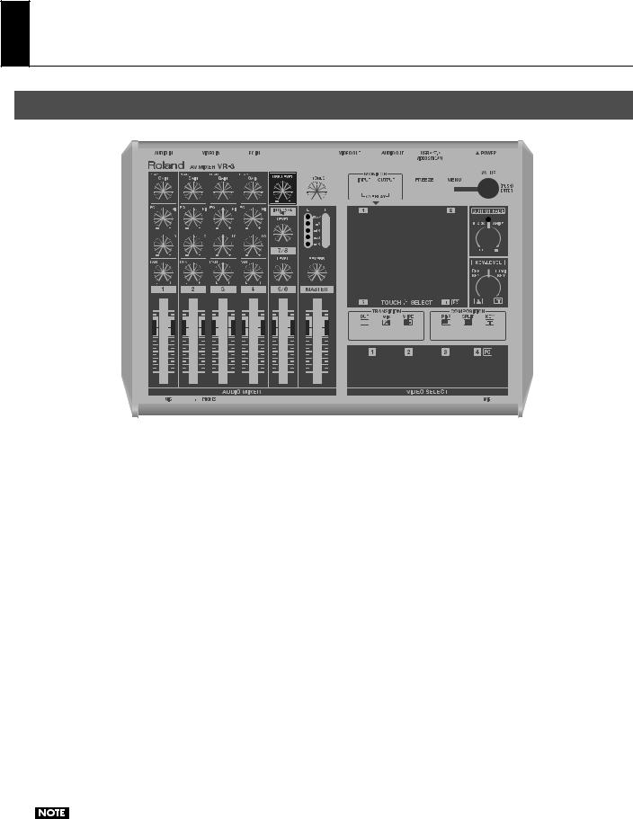
Names of Things and What They Do
Top Panel
1 |
2 |
3
1.Audio Mixer Section (p. 11)
This section is for audio mixing. Use the dials and faders to adjust the input sensitivity, output levels, and other values for each channel.
2.Video Select Section (p. 12)
This section is for switching and compositing video. Use the buttons and dials to select transition effects and compositing modes.
3.Internal Stereo Microphones
Internal microphones for picking up ambient audio are located on the left and right sides of the top panel. To adjust the level, use [LEVEL] dial of [INTERNAL MIC].
When adjusting buttons or faders, some handling noise may be heard in the internal microphones.
10
Names of Things and What They Do
Audio Mixer Section
1
2
3
4
1.GAIN Dials and PEAK Indicators
Use the [GAIN] dials to adjust the input sensitivity for channels 1 through 4. When the volume level exceeds the maximum input level, the corresponding [PEAK] indicator lights up. Excessive input volume may result in clipping or distortion. Set the [GAIN] dials for adequate audio level without clipping.
2.EQ Dials (p. 26)
Use the [Hi] dials to emphasize or attenuate the high band. Use the [Lo] dials to emphasize or attenuate the low band.
3.PAN Dials (p. 26)
These adjust the stereo position of the respective channels.
4.Channel Faders (p. 25)
These faders adjust the amount of signal being sent from each channel and the amount of signal each channel sends to the final output (MASTER).
5.USB LEVEL Dial (p. 40)
This adjusts the audio level for USB output.
6.PHONES Dial
This adjusts the level for headphones output.
5 |
6 |
7 |
8 |
9 |
10 |
11 |
7.INTERNAL MIC LEVEL Dial (p. 26)
This adjusts the level for the internal microphones.
8.Level Meter (p. 28)
This displays the audio output level. If [OVER] lights up, distortion might occur. Turn down the [MASTER] level if the [OVER] indicator lights up.
9.7/8 LEVEL Dial
This adjusts the level of audio input coming from a computer connected to the [7/8] connector on the rear panel.
10.REVERB Dial (p. 28)
This adjusts the amount of reverb applied to output.
11.MASTER Fader (p. 28)
This adjusts the level for final output.
11

Names of Things and What They Do
Video Select Section
1
2
3
4
1.MONITOR Buttons
These switch the view mode for the monitor. Choose a mode from the followings.
•[INPUT]
This displays the inputs from the respective source devices.
•[OUTPUT]
This displays the result of video mixing on the VR-3 (the final output).
•OVERLAY
When the [INPUT] button and [OUTPUT] button are pressed simultaneously, the output picture is overlaid on a four-way split screen of the input.
2.Monitor
When the view mode is set to [INPUT], you can switch the video by touching the screen. When the mode is set to [OUTPUT], you can adjust the position and size of the Picture-in-Picture (PinP) inset screen. Menus are also displayed here.
* During two-screen compositing, the background picture can be switched by touching the screen.
3.TRANSITION Buttons (p. 22)
You can select a transition effect for the video using these buttons. When switching from one video source to another, this effect will be applied during the transition.
5
6
7
8
9
4.VIDEO SELECT Buttons (p. 23)
You can use these buttons to switch the video instead of the touch panel.
*During two-screen compositing, use buttons [1] through [4] to switch the inset screen or foreground picture.
5.FREEZE Button (p. 24)
Use this button to freeze the final output image.
6.MENU Button and VALUE Dial (p. 44)
Use the [MENU] button to call up various menus on the VR-3. The menus are displayed on the monitor.
The [VALUE] dial is for changing settings. Press the [VALUE] dial to apply a new setting (ENTER).
*You can change a setting value up or down by ten units at a time by holding the [VALUE] dial down while you turn it.
7.OUTPUT FADE Dial (p. 24)
Use this when you want to apply a fade-in or fade-out to final output from the VR-3. Turning the dial counterclockwise applies a black fade, and turning it clockwise applies a white fade. Applying a fade makes the indicator above the dial flash.
12
Names of Things and What They Do
8.KEY LEVEL Dial (p. 35, p. 37)
This adjusts the degree of the extraction (removal) in key compositing. The extraction color for key compositing differs according to the direction in which you turn the dial. At the center position, no extraction at all occurs. (The background video is not visible.) Turning the dial all the way clockwise or counterclockwise enables complete extraction, and the foreground picture is not visible. Turn the dial slowly to find the optimal degree of extraction.
• |
[LUMI KEY] |
Turning the dial clockwise enables luminance-key compositing. Black or white backgrounds are extracted. |
• |
[CHR KEY] |
Turning the dial counterclockwise enables chroma-key compositing. Blue or green backgrounds are extracted. |
*In the factory-default state, black is the extraction color for luminance-key compositing, and blue is the extraction color for chroma-key composition. You can use the menus to change the extraction color. Refer to “Menu Operations” (p. 44) and “VIDEO Menu” (p. 45).
Examples of Key Compositing
 Black (or White)
Luminance Key
Chroma Key
Blue (or Green)
9. COMPOSITION Buttons (p. 29, p. 33, p. 34)
You can select a composition mode from below using buttons here.
• [PinP] |
This performs Picture-in-Picture compositing. |
|
• |
[SPLIT] |
This performs compositing with the screen split vertically or horizontally. |
• |
[KEY] |
This performs compositing using chroma key or luminance key. |
13
Names of Things and What They Do
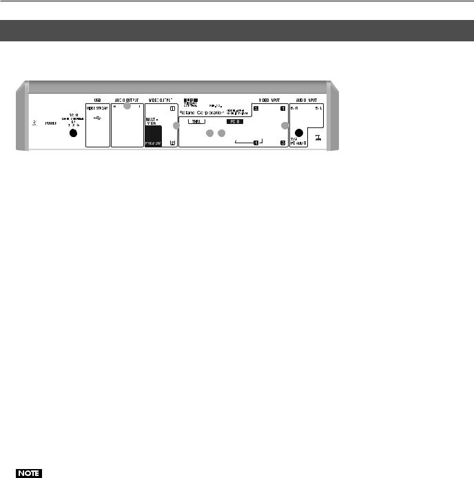
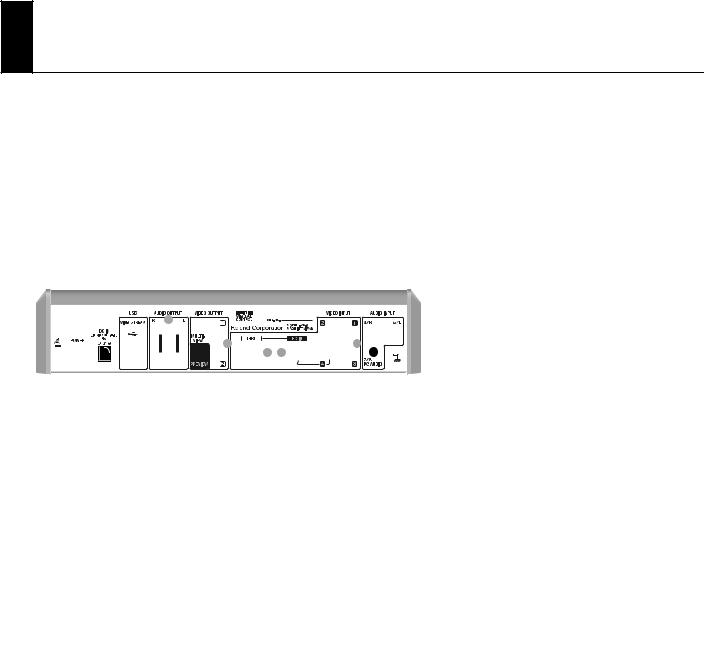
Rear Panel
1 |
2 |
3 |
|
|
4 |
|
|
5 |
6 |
|
|
|
|
|
7 |
|
8 |
|||||||||
|
|
|
|
|
|
|
|
|
|
|
|
|
|
|
|
|
|
|
|
|
|
|
|
|
|
|
|
|
|
|
|
|
|
|
|
|
|
|
|
|
|
|
|
|
|
|
|
|
|
|
|
|
|
|
|
|
|
|
|
|
|
|
|
|
|
|
|
|
|
|
|
|
|
|
|
|
|
|
|
|
|
|
|
|
|
|
|
|
|
|
|
|
|
|
|
|
|
|
|
|
|
|
|
|
|
|
|
|
|
|
|
|
|
|
|
|
|
|
|
|
|
|
|
|
|
|
|
|
|
|
|
|
|
|
|
|
|
|
|
|
|
|
|
|
|
|
|
|
|
|
|
|
|
|
|
|
|
|
|
|
|
|
|
|
|
|
|
|
|
|
|
|
|
|
|
|
|
|
|
|
|
|
|
|
|
|
|
|
|
|
|
|
|
|
|
|
|
|
|
|
|
|
|
|
|
|
|
|
|
|
|
|
|
|
|
|
|
|
|
|
|
|
|
|
|
|
|
|
|
|
|
|
|
|
|
|
|
|
|
|
|
|
|
|
|
|
|
|
|
|
|
|
|
|
|
|
|
|
|
|
|
|
|
|
|
|
|
|
|
9
1.POWER Button
This switches the power to the VR-3 on and off.
2.DC IN Connector
This is for connecting the included AC adapter.
*Use the cord hook to secure the AC adapter cord in place (p. 8).
3.USB Port
You can use this to output the results of video and audio mixing on the VR-3 to a computer.
4.AUDIO OUTPUT Connectors
These output the results of audio mixing. Connect output equipment (an amplifier or speakers) and recording equipment (such as a video recorder).
5.VIDEO OUTPUT Connectors
These output the results of video mixing. Connect output equipment (such as a projector) and recording equipment (such as a video recorder).
The PREVIEW connector is for connecting a preview monitor.
6.PC IN and THRU Connectors
You can connect RGB output from a computer to the PC IN connector and input logos, text, or still images. Input made via this connector is assigned to channel 4. When composite input and RGB input are made to channel 4 at the same time, the RGB input takes priority.
The THRU connector is for connecting a computer monitor.
Small text from a computer may not be shown clearly on the final output. If you input text, the font size should be big enough.
7.VIDEO INPUT Connectors
Use these to connect video cameras or other video sources. When composite input and RGB input are made to channel 4 at the same time, the RGB input takes priority.
*You can use the menus to lock the channel-4 input to composite or RGB. Go to the [SYSTEM] menu and select [PC IN], then use [CH4 INPUT SOURCE] to select [PC IN] or [VIDEO]. Refer to “Menu Operations” (p. 44) and “SYSTEM Menu” (p. 47).
8.AUDIO INPUT Connectors
These are for connecting the audio output of video players or other source equipment. Input made via the RCA connectors is assigned to channels 5/6.
9.PC AUDIO Connector
This is for connecting audio output from a computer. Input from the computer is assigned to channels 7/8.
14

Names of Things and What They Do
Left Side Panel
2
1 


1.PHANTOM +48V Switch (p. 19)
This switches the phantom power of the AUDIO INPUT (XLR/TRS) connectors on and off. The unit has a switch for channels 1/2 and a switch for channels 3/4.
2.AUDIO INPUT (XLR/TRS) Connectors
These are for connecting microphones or an external audio mixer, or other audio sources. Input made via these connectors is assigned to channels 1 through 4.
Right Side Panel
OUT/THRU |
IN |
MIDI IN and MIDI OUT/THRU connectors are equipped here. You can connect external MIDI devices to remote control the VR-3. Refer to “About Remote Control” (p. 48).
Front Panel
Two headphones (PHONES) connectors are located here. You can use these to connect standard-type (1/4-inch) headphones and mini-stereo headphones.
The volume levels for the two PHONES connectors cannot be adjusted independently. Operating the [PHONES] dial changes the volume for both simultaneously.
15

Names of Things and What They Do
Signal Flow
Signal flow inside the VR-3 is as shown in the figure below.
RGB
Converter
1 |
2 |
3 |
4 |
Video Mixer
|
|
PinP / Split / Key |
|
Video Fader |
Video |
|
|
|
|
|
USB |
1 |
2 |
|
3 |
4 |
|
Preview |
|
|
Audio Effects
1 |
2 |
3 |
4 |
5/6 |
7/8 |
INT MIC |
Audio Mixer
Level Master Fader / Audio Effects Level
Audio
USB |
16
Connecting External Equipment
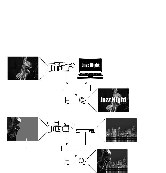
You can connect external equipment as shown below. For information on specific connections, refer to the following pages.
*To prevent malfunction and/or damage to speakers or other devices, always turn down the volume, and turn off the power on all devices before making any connections.
This unit is equipped with balanced (XLR/TRS) type jacks. Wiring diagrams for these jacks are shown below. Make connections after first checking the wiring diagrams of other equipment you intend to connect.
Howling could be produced depending on the location of microphones relative to speakers. This can be remedied by:
1.Changing the orientation of the microphone(s).
2.Relocating microphone(s) at a greater distance from speakers.
3.Lowering volume levels.
17
 Loading...