


 Version 2.0
USER GUIDE
q
Before using this unit, carefully read the sections entitled: “IMPORTANT SAFETY INSTRUCTIONS” (Owner’s Manual p. 2), “USING THE UNIT SAFELY” (Owner’s Manual p. 3, 4), and “IMPORTANT NOTES” (Owner’s Manual p. 5).
These sections provide important information concerning the proper operation of the unit. Additionally, in order to feel assured that you have gained a good grasp of every feature provided by your new unit, User Guide, Owner’s Manual, and Appendices should be read in their entirety. The manual should be saved and kept on hand as a convenient reference.
Copyright © 2002 ROLAND CORPORATION
All rights reserved. No part of this publication may be reproduced in any form without the written permission of ROLAND CORPORATION.
Roland Web site http://www.roland.co.jp/

2

Contents |
|
Contents .................................................................................................. |
3 |
Preparations ............................................................................................ |
5 |
Required Preparations ............................................................................................................................... |
5 |
Installing an Internal Hard Disk .............................................................................................................. |
5 |
Cautions When Installing a Hard Disk........................................................................................ |
5 |
Installation de dispositifs optionnels |
|
(French language for Canadian Safety Standard).................................................................................. |
8 |
Précautions à prendre lors de l’installation de dispositifs optionnels .................................... |
8 |
Installer un disque dur (série HDP35) ......................................................................................... |
8 |
Installing Effect Expansion Boards ........................................................................................................ |
11 |
Cautions When Installing an Effect Expansion Board............................................................. |
11 |
Installation de la carte d’extension d’effets |
|
(French language for Canadian Safety Standard)................................................................................ |
14 |
Précautions lors de l’installation de la carte d’extension d’effets .......................................... |
14 |
How to Replace the Battery .................................................................................................................... |
16 |
Basic Connections (Power Supply, Audio Devices and Headphones)............................................. |
18 |
Turning On the Power ............................................................................................................................. |
19 |
Adjusting the Display Contrast .................................................................................................. |
20 |
If You Do Not Understand the Display or Don’t Know What to Do .................................... |
20 |
Mixer and Utility Parameters Initialize................................................................................................. |
20 |
Setting the Date and Time of the Internal Clock.................................................................................. |
22 |
Turning Off the Power............................................................................................................................. |
23 |
Listening to the Demo Performance ................................................... |
25 |
How To Load a Demo Song (CD-R Recover)....................................................................................... |
25 |
For Making the Preparations Which Listen to a Demo Performance (Project Select) .................... |
27 |
Playing Back the Demo Performance .................................................................................................... |
28 |
Viewing the Level Meters. ........................................................................................................... |
28 |
Adjusting the Overall Volume .................................................................................................... |
29 |
Adjusting the Volume of an Individual Track.......................................................................... |
29 |
Adjusting the Headphone Volume............................................................................................. |
29 |
Listening to the Demo Performance with a Different Arrangement (Scene) .................................. |
30 |
Making a Multi-Track Recording.......................................................... |
31 |
Creating a New Project (Project New)................................................................................................... |
31 |
Connecting Microphones ........................................................................................................................ |
33 |
Cautions When Connecting Microphones ................................................................................ |
34 |
Adjusting the Input Sensitivity .............................................................................................................. |
35 |
Recording On a Track .............................................................................................................................. |
36 |
Playing Back the Performance You Recorded...................................................................................... |
38 |
Canceling the Recording ......................................................................................................................... |
39 |
Canceling a Record Result (Undo) ............................................................................................. |
39 |
Canceling the Undo (Redo) ......................................................................................................... |
39 |
Re-Recording a Specified Portion (Punch-In/Punch-Out) ..................................................... |
40 |
Erasing Just a Portion of a Recording (Track Erase) ................................................................ |
41 |
Recording On a V.Track .......................................................................................................................... |
42 |
Comparing the Recorded content of Two V.Tracks ............................................................................ |
43 |
Recording On Other Tracks (Overdubbing)......................................................................................... |
44 |
Playing Back Two or More Tracks ......................................................................................................... |
45 |
Adjust the Volume Balance of the Tracks.................................................................................. |
45 |
Adjusting the Stereo Position of Each Track............................................................................. |
46 |
Use the Equalizer To Adjusting the Tone of Each Track......................................................... |
46 |
Use the Filter To Adjusting the Tone of Each Track ................................................................ |
47 |
Saving Your Performance (Project Store).............................................................................................. |
49 |
Contents
3

Contents
Using Effects ......................................................................................... |
50 |
Selecting the effect patch you wish to use ............................................................................................ |
50 |
Selecting the effect bus assignment ....................................................................................................... |
52 |
Applying a Loop Type Effect During Playback................................................................................... |
53 |
Applying a Loop Type Effect Only to the Monitor Sound as You Record ...................................... |
55 |
Switching Effects During Playback........................................................................................................ |
57 |
Applying a Loop Type Effect While You Record ................................................................................ |
59 |
Applying an Insertion-Type Effect During Playback.......................................................................... |
61 |
Applying an Insertion-Type Effect During Recording ....................................................................... |
64 |
Add Finishing Touches to Your Project ............................................. |
67 |
Combining the Performances of Multiple Tracks (Track Bouncing) ................................................ |
67 |
Mixing down to the mastering tracks (Mastering Room) .................................................................. |
72 |
Mixing down to the mastering tracks ........................................................................................ |
72 |
Playing back the mastering tracks ......................................................................................................... |
75 |
Erasing an Unwanted Portion (Track Cut) ........................................................................................... |
77 |
Selecting the Portion that will be Written to the CD-R disc ................................................... |
77 |
Deleting an Unwanted Portion At the End of the Project....................................................... |
78 |
Deleting an Unwanted Portion At the beginning of the Project ............................................ |
79 |
Adding Track Number Markers ............................................................................................................ |
80 |
Assigning Track Numbers ........................................................................................................... |
81 |
Erasing Track Number Markers ................................................................................................. |
81 |
Creating an Original Audio CD ............................................................ |
82 |
Connecting the CD-R/RW Drive ........................................................................................................... |
82 |
Writing a Project to a CD-R/RW disc ................................................................................................... |
82 |
Auditioning the Project You Wrote ....................................................................................................... |
86 |
About the Demo Performances ........................................................... |
87 |
Index....................................................................................................... |
89 |
4

Preparations
Required Preparations
The VS-2480/2480CD is an audio recorder that allows multi-track recording to a hard disk. To make a multi-track recording, you will need at least the following items.
•VS-2480/2480CD
•Power cable (1: included)
•Internal IDE hard disk (HDP35 series: sold separately in some countries)
•Audio device for master output, monitor output, or headphones (sold separately)
•Microphone or other audio source to record, such as an electric guitar, synthesizer, or CD player etc. (sold separately)
•Short Cut Seal
User guide will also explain the use of the following equipment, which you may purchase as desired.
•VS8F-2 (effect expansion board: The VS-2480/2480CD contains one VS8F-2, sold separately for increase.)
•External CD-R/RW drive (sold separately)
IDE (Appendices p.12)
The CD-R/RW drive becomes necessary without fail to Recover the demo performance to the HDP35 series from CD-ROM of a belonging.
Installing an Internal Hard Disk 
In some countries, VS-2480’s do not come with the Hard Disk
installed. A Roland HDP35 series hard disk (sold separately in some countries) can be installed in the VS-2480. In order to take full advantage of the VS-2480’s functionality for the number of tracks that can be recorded/played back simultaneously, we recommend that you install the HDP35-40G or higher model.
 The VS-2480CD contains an internal 80 GB hard disk. The procedure described below is not required.
■Cautions When Installing a Hard Disk
•Use a Philips screwdriver that is suitable for the size of the screw (a number 2 screwdriver). If an unsuitable screwdriver is used, the head of the screw may be stripped.
•To remove a screw, rotate the screwdriver counter-clockwise. To tighten a
screw, rotate the screwdriver clockwise.
fig.01-01e
loosen |
tighten |
•When installing a hard disk, remove only the specified screws.
•Be careful that the screws you remove do not drop into the interior of the VS-2480.
•Do not leave the front panel cover in a detached state. Be sure to reattach it after the hard disk has been installed.
•Do not touch any of the printed circuit pathways or connection terminals.
•Be careful not to cut your hand on the edge of the installation bay.
•When circuit board installation is complete, double-check your work.
1.Turn off the power of the VS-2480 and of all connected devices, and disconnect all cables from the VS-2480.
The explanations in this manual include illustrations that depict what should typically be shown by the display. Note, however, that your unit may incorporate a newer, enhanced version of the system, so what you actually see in the display may not always match what appears in the manual.
The VS-2480 saves all of the data, such as performance data, mixing data, system data, etc., on a hard disk drive. Thus, it cannot operate without either having the HDP35 series hard disk.
Preparations
5

Preparations
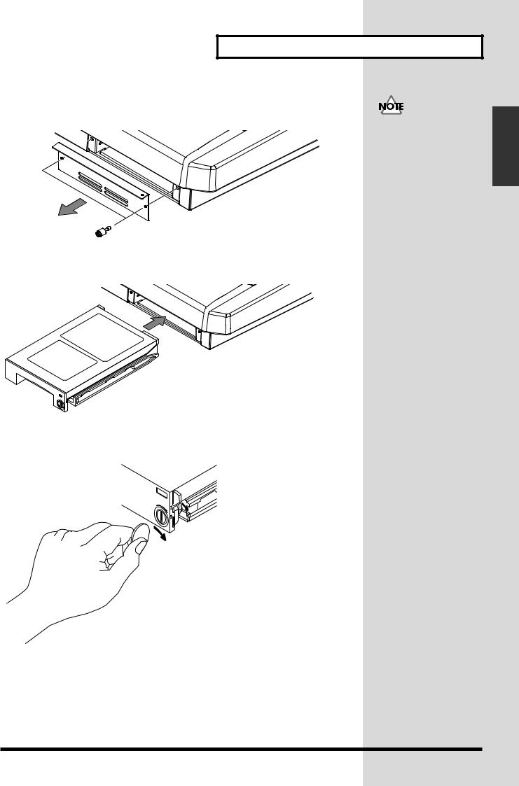
2.Remove the front panel cover from the VS-2480.
fig.01-02_50
3.With the warning label of the hard disk facing upward, slide it gently into the installation bay as far as it will go. You can hook the indentation of the attachment hardware over the protrusion on the chassis of the VS-2480.
fig.01-03_40
4.After you install the hard disk to the unit you use, please lock it to fix. Apply a coin, etc. to the lock and turn it clockwise until it clicks and it is locked correctly.
fig.01-04
LOCK
5.Reattach the front panel cover as it originally was.
The hard disk inside the VS-2480CD cannot be removed or exchanged.
When transporting the VS-2480, please pack it in the original carton and shock-absorbing material, or the equivalent. If an internal IDE hard disk (HDP35 series) is installed, reverse the installation procedure to remove it from the VS-2480, pack the hard disk in its own packing carton for transport. If the VS-2480 is transported with the hard disk installed, project data may be lost, or the hard disk itself may be damaged.
6

Preparations
fig.01-05_50
When you turn on the
power after an unformatted
disk has been installed, the
"Format Drive" screen will appear automatically. Follow the displayed instructions to format the
disk.
6. As described in “Turning On the Power (p. 19),” turn on the power and verify that the VS-2480 starts up correctly.
If the Display Indicates “Not Found any Drives”
The internal hard disk was not recognized correctly. Use the rear panel power switch to turn off the power (p. 23), and re-install the hard disk correctly.
fig.dialog-NotFoundDrive
Preparations
7

Preparations
Installation de dispositifs optionnels
(French language for Canadian Safety Standard)
■Précautions à prendre lors de l’installation de dispositifs optionnels
•Toujours éteindre et débrancher l’appareil avant de commencer l’installation de la carte. (modèle no série HDP35; User Guide p. 23).
•N’installez que les cartes de disque dur spécifiées (modèle no série HDP35). Enlevez seulement les vis indiquées.
•Veuillez suivre attentivement les instructions suivantes quand vous manipulez la carte afin d’éviter tout risque d’endommagement des pièces internes par l’électricité statique.
•Toujours toucher un objet métallique relié à la terre (comme un tuyau par exemple) avant de manipuler la carte pour vous décharger de l’électricité statique que vous auriez pu accumuler.
•Lorsque vous manipulez la carte, la tenir par les côtés. Évitez de toucher aux composants ou aux connecteurs.
•Conservez le sachet d’origine dans lequel était la carte lors de l’envoi et remettez la carte dedans si vous devez la ranger ou la transporter.
•Veillez à ne pas laisser tomber de vis dans le châssis du VS-2480.
•Ne pas toucher aux circuits imprimés ou aux connecteurs.
•Ne jamais forcer lors de l’installation de la carte de disque dur. Si la carte s’ajuste mal au premier essai, enlevez la carte et recommencez l’installation.
•Quand l’installation de la carte de disque dur est terminée, revérifiez si tout est bien installé.
■Installer un disque dur (série HDP35)
Le VS-2480 s’utilise avec un disque dur Roland de la série HDP35 vendu séparément. Pour maximiser les capacités du VS-2480 -nombre de pistes lors des enregistrements et lectures simultanés ou taille de la mémoire-, il est conseillé d’utiliser un modèle supérieur au 40 GB.
1.Éteindre tous les appareils reliés au VS-2480 et détacher tous les câbles qui y sont reliés.
8
Preparations
2.Enlever les vis indiquées sur le schéma suivant et détacher la plaque avant du VS-2480.
fig.38
3.Orienter le disque dur de façon à ce que la face sur laquelle est collée l’étiquette de mise en garde se trouve sur le dessus.
Afin d’éviter d’infliger des dommages à l’appareil lors de déplacements, enlever le disque dur installé en suivant, dans le sens contraire, les étapes de son installation de la p. 6. Il est impératif d’enlever le disque dur du VS-2480 lors de déménagement ou d’envoi. Lors de tels déplacements, ne pas oublier de bien remettre le disque dur dans son emballage d’origine et de placer le disque emballé dans l’espace prévu à cet effet dans la boîte d’emballage du VS-2480.
4.Après avoir installé le disque dur dans le VS-2480, fixez-le bien afin qu'il ne se détache pas.
LOCK
Preparations
9

Preparations
5.Pour ce faire, insérez une pièce de monnaie dans la fente et tournez dans le sens des aiguilles d'une montre jusqu'à ce que vous entendiez un déclic.
6.Cela signifie que le disque est bien fixé.
Les vis peuvent s’enlever avec les doigts. Si elles sont trop serrées pour être dévissées avec les doigts, vous pouvez utiliser une pièce de monnaie.
Si le message “Not Found any Drives” s’affiche, cela signifie que le disque dur installé n’est pas reconnu correctement. Éteindre l’appareil avec le bouton arrière et
recommencer l’installation du disque dur.
fig.01-06
10
Installing Effect Expansion Boards
The VS-2480/2480CD contains one VS8F-2 effect expansion board (EFFECT A section).
An additional three VS8F-2 boards can be installed in the VS-2480/2480CD. When four VS8F-2 boards are installed, you will be able to use up to eight stereo effects simultaneously.
■ Cautions When Installing an Effect Expansion Board
lTo avoid the risk of damage to internal components that can be caused by static electricity, please carefully observe the following whenever you handle the board.
•Before you touch the board, always first grasp a metal object (such as a water pipe), so you are sure that any static electricity you might have been carrying has been discharged.
•When handling the board, grasp it only by its edges. Avoid touching any of the electronic components or connectors.
•Save the bag in which the board was originally shipped, and put the board back into it whenever you need to store or transport it.
•Use a Phillips screwdriver that is suitable for the size of the screw (a number 2 screwdriver). If an unsuitable screwdriver is used, the head of the screw may be stripped.
•To remove a screw, rotate the screwdriver
counter-clockwise. To tighten a screw, rotate the loosen |
tighten |
screwdriver clockwise. |
|
fig.01-07j
•When installing effect expansion boards, remove only the specified screws.
•Be careful that the screws you remove do not drop into the interior of the VS-2480/2480CD.
•Do not leave the bottom cover in a detached state. Be sure to reattach it after the effect expansion boards have been installed.
•Do not touch any of the printed circuit pathways or connection terminals.
•Be careful not to cut your hand on the edge of the installation bay.
•Never use excessive force when installing a circuit board. If it doesn’t fit properly on the first attempt, remove the board and try again.
•When circuit board installation is complete, double-check your work.
1.Before installing the VS8F-2, turn off the power of the VS-2480/2480CD and all connected devices, and disconnect all cables from the VS-2480/2480CD.
2.Turn the VS-2480/2480CD on its back, and remove only the screws shown in the following diagram.
Preparations
Preparations
11

Preparations
fig.01-08_50
EFFECT B
EFFECT D
EFFECT C
EFFECT A
3.Inside, there are four connectors and 12 resin pins. Insert the connectors of the VS8F-2 in to the internal connectors, and simultaneously insert the resin pins into the holes of the VS8F-2 to fasten the unit in place.
4.Use the screws that you removed in step 2 to fasten the cover back in place. This completes installation of the effect expansion board.
5.Connect the cables that you disconnected earlier.
6.Turn on the power, as described in “Turning On the Power (p. 19).”
7.After proper startup of the VS-2480/2480CD, press [EFFECT] and confirm that the FX 1 and 2 icons are displayed. If two VS8F-2 units are installed, press [EFFECT] and confirm that the icons for FX 1–4 are displayed.
When turning the unit upside-down, get a bunch of newspapers or magazines, and place them under the four corners or at both ends to prevent damage to the buttons and controls. Also, you should try to orient the unit so no buttons or controls get damaged.
When turning the unit upside-down, handle with care to avoid dropping it, or allowing it to fall or tip over.
Install VS8F-2 effect expansion boards in the order of EFFECT A, EFFECT B, EFFECT C, and EFFECT D. Do not skip slots when installing these boards.
The VS-2480/2480CD comes equipped with one internal effects expansion board (containing two effects processors).
12

Preparations
fig.01-09(FXAssign)
Preparations
If the Display Indicates “No EFFECT Board”
The internal effect expansion board was not detected correctly. Turn off the power (Shutdown operation), as described in “Turning Off the Power (p. 23),” and re-install the effect expansion board correctly.
13

Preparations
Installation de la carte d’extension d’effets
(French language for Canadian Safety Standard)
Quand une ou deux cartes VS8F-2 sont installées, il est possible d’utiliser jusqu’à 2 effets stéréo pour chaque carte sans brancher aucun équipement additionnel au VS-2480/2480CD. Deux de ces cartes peuvent être installées dans le VS-2480/2480CD. Il est recommandé d’installer au moins une carte d’extension à effet pour pouvoir utiliser pleinement le VS-2480/2480CD.
■ Précautions lors de l’installation de la carte d’extension d’effets
●Pour éviter tout dommage des composants internes pouvant provenir de l’électricité statique, veuillez suivre les conseils suivants quand vous installez la carte.
•Avant de toucher la carte, saisissez toujours un objet métallique (tuyau d’eau ou autre) pour être sûr que l’électricité statique se décharge.
•Quand vous saisissez la carte, prenez-la par les bords. Evitez de toucher les composants électroniques ou les connecteurs.
•Conservez le sac dans lequel la carte était emballée et remettez la carte dedans pour l’expédier ou l’entreposer.
●Utiliser un tournevis cruciforme correspondant à la taille de la vis (un tournevis
numéro 2). En cas d’utilisation d’un tournevis inapproprié, la tête de la vis pourrait |
|||
être endommagée. |
|
|
|
●Pour enlever les vis, tourner le tournevis dans |
|
|
|
|
|
||
le sens contraire des aiguilles d’une montre. Pour |
desserrer |
resserrer |
|
resserrer, tourner dans le sens des aiguilles d’une |
|||
|
|
||
montre. |
|
|
|
|
|
||
●Lors de l’insertion de la carte d’extension |
|
|
|
d’effets, enlevez seulement les vis indiquées dans les instructions. |
|
||
●Veillez à ne pas laisser tomber de vis dans le châssis du VS-2480/2480CD. ●Ne pas laisser le panneau de protection avant détaché. S’assurer de l’avoir rattacher après avoir installé le disque dur.
●Ne touchez aucun des circuits imprimés ni les bornes de connexion.
●Veillez à ne pas vous couper les doitgs sur le bord de l’ouverture d’installation. ●Ne jamais forcer quand vous installez une carte de circuits. Si la carte ne rentre pas correctement, ressortez-la et ressayez.
●Quand la carte est installée, vérifiez si l’installation est correcte.
1.Éteindre le VS-2480/2480CD et tous les appareils qui y sont reliés et débrancher tous les câbles du VS-2480/2480CD.
Lorsque vous retournez à l'envers le VS-2480/2480CD, posez-le sur une surface molle afin de ne pas abîmer le tableau de commande ou l'écran de commande. Retournez le VS-2480/2480CD et enlevez seulement les vis indiquées sur la figure.
14

Preparations
2.A l’intérieur se trouvent deux connecteurs et 12 goupilles de plastique. Reliez les connecteurs de la VS8F-2 à ceux du VS-2480/2480CD tout en insérant les goupilles de plastique dans les orifices de la VS8F-2.
fig.1-05.f
|
Si vous installez une seule |
|
carte d’extension d’effets, |
|
installez-la dans |
EFFECT B |
EFFECT A. |
EFFECT D
EFFECT C
EFFECT A
3.Reposez le couvercle en remettant les vis enlevées (comme spécifié) à l’étape 2. L’installation de la carte d’extension d’effets est terminée.
4.Rabranchez les câbles.
5.Mettez le VS-2480/2480CD sous tension en procédant comme indiqué dans “Turning On the Power (p. 19).”
6.Si le VS-2480/2480CD démarre normalement, appuyez sur la touche [EFFECT] et assurez-vous que les icônes FX 1,2 s'affichent. Si vous avez installé deux VS8F-2, lorsque vous appuyez sur la touche [EFFECT] , assurez-vous que les icônes FX 1--4 s'affichent.
Si “No EFFECT Board” apparaît à l’écran
Ce message signifie que la carte d’extension d’effets n’a pas été reconnue correctement. Mettez l’appareil hors service et hors tension comme indiqué dans “Mise hors tension”, puis réinstallez correctement le VS8F-2.
Preparations
15

Preparations
How to Replace the Battery
A lithium battery inside the unit powers its time-keeping functions, and provides the power for maintaining information about certain parameters. Once this battery gets weak, the unit may no longer be able to reliably perform the time management functions for data, or return to the state is was in before power was turned off. If you see a message warning that the battery is depleted, promptly change the battery, following the procedure below.
fig.01-10(BattLow)
1.Before changing the lithium battery, store the current project (p. 49).
2.Turn off the power of VS-2480/2480CD and all connected devices, and disconnect all cables from VS-2480/2480CD.
3.Turn the VS-2480/2480CD on its back, and remove only the screws shown in the following diagram.
fig.01-10a_50
16

Preparations
fig.battery1_69
Preparations
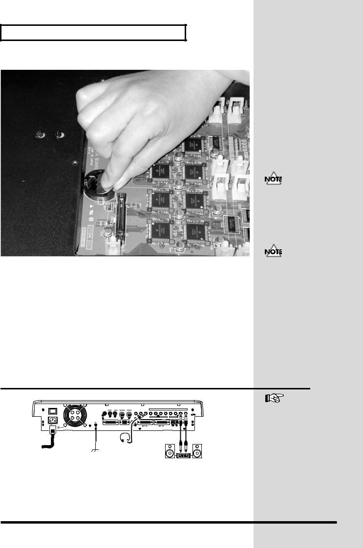
4.The battery should now be visible, as shown in the following.
fig.battery2_69
CR2032
When turning the unit upside-down, get a bunch of newspapers or magazines, and place them under the four corners or at both ends to prevent damage to the buttons and controls. Also, you should try to orient the unit so no buttons or controls get damaged.
5.If Effect Expansion Board (VS8F-2) installed on the EFFECT A section, remove the VS8F-2 of the EFFECT A section.
6.Replace the old battery with a new one.
17
Preparations
fig.battery3_69
7.Reinstall the effect expansion board (VS8F-2) if removed in Step 5. Insert the plastic pin in the VS8F-2’s hole, making sure the board is securely fastened in place.
8.Use the screws that you removed in step 2 to fasten the cover back in place. This completes the process of exchanging the lithium battery.
9.Connect the cables that you disconnected earlier.
10.Turn on the power, as described in “Turning On the Power (p. 19).”
11.Confirm that the message warning that the lithium battery is depleted does not appear in the display.
12.Set the current time (p. 22).
Basic Connections (Power Supply, Audio
Devices and Headphones)
A CR2032 lithium battery is used for the VS-2480/2480CD. This type of battery is available at an electric appliance, or similar store.
The internal clock is powered by the lithium battery. Changing the lithium battery may cause this clock to stop, or may result in the current time being altered. Always make sure to newly set the correct time after the lithium battery has been replaced.
fig.01-11j_60
POWER |
|
|
|
|
|
|
|
|
|
|
|
|
|
|
|
|
|
THIS DEVICE COMPLIES WITH PART 15 OF |
SMPTE |
PS / 2 |
|
MIDI |
FOOT |
|
|
|
|
ANALOG MULTI OUTPUT +4dBu BALANCED / -2dBu UNBALANCED |
|
||||
ON |
THE FCC RULES. OPERATION IS SUBJECT |
KEYBOARD MOUSE |
OUT / THRU |
IN |
PHONES 2 |
PHONES 1 |
8 |
7 |
6 |
5 |
4 |
3 |
2 |
1 |
||
TO THE FOLLOWING TWO CONDITIONS: |
IN |
SWITCH |
||||||||||||||
|
(1) THIS DEVICE MAY NOT CAUSE HARMFUL |
|
|
|
|
|
|
|
|
|
|
|
|
|
|
GND COLD |
|
INTERFERENCE, AND (2) THIS DEVICE MUST |
|
|
|
|
|
|
|
|
|
|
|
|
|
|
|
|
ACCEPT ANY INTERFERENCE RECEIVED, |
|
|
|
|
|
|
|
|
|
|
|
|
|
|
(SLEEVE) (RING) |
|
INCLUDING INTERFERENCE THAT MAY |
|
|
|
|
|
|
|
|
|
|
|
|
|
|
HOT |
AC IN |
CAUSE UNDESIRED OPERATION. |
|
|
|
|
|
|
|
|
|
|
|
|
|
|
(TIP) |
|
|
|
|
|
|
|
|
R |
L |
R |
L |
R |
L |
R |
L |
|
|
|
|
|
|
|
|
|
|
|
MONITOR |
|
AUX B |
|
AUX A |
|
MASTER |
|
|
|
|
|
|
|
|
|
|
|
|
DIGITAL |
|
|
|
|
SCSI |
VGA OUT |
WORD CLOCK IN |
2 |
1 |
OUT |
IN |
OUT |
IN |
|
|
|
DIGITAL 8ch I / O |
DIGITAL 8ch I / O |
OPTICAL |
COAXIAL |
||
For details refer to Owner’s Manual “Working with the VS-2480 Output. (p. 287)”
Stereo Headphones (RH-25, RH-50, etc.)
To Power Outlet |
Ground (Earth) |
Stereo Set, etc.
If you are using headphones, connect them to the rear panel PHONES 1 or PHONES 2 jack. The PHONES jack will output the same signal as the MONITOR jacks. When you purchase the VS-2480/2480CD, it will be set so that all analog audio signals are output from the MASTER jacks. The MONITOR jacks will output the same sound as the MASTER jacks.
fig.01-12
18

Preparations
Be sure to ground the device to prevent any minor leakage of current from the
VS-2480/2480CD, connectors, or other possible sources.
The VS-2480/2480CD Support the “Mouse” and
the “VGA Monitor”
The VS-2480/2480CD has a “Mouse connector” that allows a mouse to be connected. If a mouse is connected, you will be able to use a mouse to operate the buttons and control knobs that appear in the display of the VS-2480/2480CD.
If a personal computer VGA monitor is connected to the “VGA connector,” you can view your operations on a larger screen than the display built into the VS-2480/2480CD
Turning On the Power
To prevent malfunction and/or damage to speakers or other devices, always turn down the volume before making any connections.
Do not connect a mouse to the keyboard connector. It becomes the cause of malfunction.
1.The rear panel POWER switch turns on the power of the VS-2480/2480CD. Use the rear panel POWER switch to turn on the power of the VS-2480/2480CD. The current system version number will be displayed with the opening
screen. Please wait. |
System Version # |
fig.01-13
2.When the VS-2480/2480CD starts up correctly, the following display (Home Condition screen) will appear.
3.Turn on the power of your audio system.
4.Raise the volume of your audio system to an appropriate level.
Always make sure to have the volume level turned down before switching on power. Even with the volume all the way down, you may still hear some sound when the power is switched on, but this is normal, and does not indicate a malfunction.
Once the connections have been completed (p. 18), turn on power to your various devices in the order specified. By turning on devices in the wrong order, you risk causing malfunction and/or damage to speakers and other devices.
When the power is turned on, the disk drive will be detected, and necessary data will be read. For this reason there will be an interval of time before operation can begin.
Preparations
19
Preparations
■ Adjusting the Display Contrast |
CONTRAST |
fig.01-14_50 |
|
|
The text or icons in the VS-2480/2480CD’s display (Operation |
|
|
Display) may be difficult to read immediately after the unit is turned |
PHONES 1 |
|
on or after it has been used for long periods, or depending on the |
|
|
environment in which the unit is used. If this occurs, rotate the |
0 |
10 |
CONTRAST knob located at the left side of the display to adjust the |
PHONES 2 |
|
|
|
|
display contrast. |
0 |
10 |
|
||
|
MONITOR |
|
Operating the CONTRAST knob will not affect the screen displayed by the VGA monitor connected to the VGA connector.
■If You Do Not Understand the Display or Don’t Know What to Do
DISPLAY
F4 |
F5 |
F6 |
HOME |
fig.01-15
If an unfamiliar display appears or if you do not know how you arrived at the current condition, press
[HOME (DISPLAY)]. This will return you to the initial power-on screen, allowing you to re-do the procedure from the beginning.
Mixer and Utility Parameters Initialize
You can restore the default parameter settings of a project. This is convenient when you have made many changes to the Input Mixer, the Track Mixer, the Master Block, as well as changes in the System Menu screens, and you want to quickly restore the VS-2480/2480CD to its default settings.
•If you attempt to perform an incorrect operation or if the specified operation cannot be executed, an error message will appear in the display. Please refer to “Error Messages” (Appendices p. 9) and take the appropriate action.
•If the results are not as described in the User Guide or Owner’s Manual even though you have followed the specified steps, please refer to “Troubleshooting” (Appendices p. 5).
•If the information in “Troubleshooting” does not resolve the problem, contact a nearby Roland Service Center or authorized Roland Distributor.
After initializing mixer and system settings, many settings will not be affected. Some of the settings that are not affected by Mixer and System Initialize include project, Scene, tempo map, and sync track data. Additionally, the IDE drive, SCSI ID, Scene Mode, Shift Lock, and Numerics Type settings are not changed as a result of Mixer/System Initialize.
20
fig.01-17_50
2 |
|
|
|
|
5 |
3 |
DISPLAY |
PAGE |
F1 |
F2 |
F3 |
F4 |
F5 |
F6 |
HOME |
EZ |
|
|
|
TRACK EDIT |
|
|
ROUTING |
COPY |
MOVE |
TRIM IN |
TRIM OUT |
DELETE |
SPLIT |
PATCH BAY |
COPY |
MOVE |
INSERT |
CUT |
ERASE |
COMP / EXP. |
|
||||||
AUTOMIX |
A.PUNCH |
IN |
OUT |
FROM |
TO |
LOOP |
|
||||||
CD-RW |
MENU |
|
|
MASTERING PROJECT |
TRACK |
EFFECT |
UTILITY |
1 |
MIDI / DISK |
|
LOCATOR / MARKER / SCENE |
|
||
LOCATOR |
7 |
8 |
9 |
SCENE |
BANK |
AUX 7 |
AUX 8 |
USER |
BANK |
MARKER |
4 |
5 |
6 |
|
|
AUX 4 |
AUX 5 |
AUX 6 |
|
|
1 |
2 |
3 |
|
|
AUX 1 |
AUX 2 |
AUX 3 |
|
|
PREVIOUS |
0 / - |
NEXT |
SHIFT |
|
|
|
|
|
NEW PHRASE
IMPORT 
 REGION GRADATION
  AUTOMIX
WAVE DISP |
UNDO |
|
REDO |
+
ZOOM +
TIME / VALUE
SHUTTLE
4 |
PREVIEW
TO |
THRU |
FROM |
EXT SYNC |
ENTER |
EXIT |
|
SCRUB |
|
|
/ YES |
/ NO |
|
|
PROJECT TOP |
PROJECT END |
|
|
|
|
|
ZERO |
STOP |
PLAY |
REC |
|
|
|
STORE |
SHUT / EJECT |
RESTART |
AUTOMIX REC |
|
6 |
6 |
1.Press [UTILITY]. Utility Menu screen will appear.
2.Press [PAGE] several times until function tab “Page3” will be appeared at the front.
3.Press [F6 (PrmIni)]. MIXER/UTILITY Parameter Initialize screen will appear.
4.Use TIME/VALUE dial to select the parameter that you wish to initialize.
5.Press [F5 (OK)].
6.“Initialize Parameter?” message will appear. If you wish to initialize, press
[ENTER/YES]. If you wish to cancel the operation, press [EXIT/NO].
fig.dialog-initparam
Preparations
Preparations
21
Preparations
Setting the Date and Time of the Internal
Clock
The VS-2480/2480CD contains a clock. When you record a performance, a time stamp is added which indicates the date and time of the recording. This is a convenience that helps you keep track of the date or order in which recordings were made. After turning on the power for the first time after purchase, please use the following procedure to set the date and time of the internal clock.
fig.01-19_50
2 |
|
|
|
|
3,5 |
|
6 |
|
|
|
|
|
DISPLAY |
||
PAGE |
F1 |
F2 |
F3 |
F4 |
F5 |
F6 |
HOME |
EZ |
|
|
|
TRACK EDIT |
|
|
|
|
ROUTING |
COPY |
MOVE |
TRIM IN |
TRIM OUT |
DELETE |
SPLIT |
NEW |
PHRASE |
PATCH BAY |
COPY |
MOVE |
INSERT |
CUT |
ERASE |
COMP / EXP. |
IMPORT |
REGION |
|
GRADATION |
AUTOMIX |
||||||
|
|
|
|
|
|
|
||
AUTOMIX |
A.PUNCH |
IN |
OUT |
FROM |
TO |
LOOP |
WAVE DISP |
UNDO |
|
||||||||
|
|
|
|
|
|
|
|
REDO |
CD-RW |
|
MENU |
|
|
|
|
4 |
|
MASTERING |
PROJECT |
TRACK |
EFFECT |
UTILITY |
|
|
+ |
|
1 |
|
|
|
|
MIDI / DISK |
|
||
|
LOCATOR / MARKER / SCENE |
|
|
|
ZOOM |
+ |
||
|
7 |
8 |
9 |
|
|
|
||
LOCATOR |
SCENE |
|
|
|
|
|||
BANK |
AUX 7 |
AUX 8 |
USER |
BANK |
|
|
|
|
|
4 |
5 |
6 |
|
|
|
TIME / VALUE |
|
MARKER |
|
|
|
SHUTTLE |
|
|||
|
|
|
|
|
||||
|
AUX 4 |
AUX 5 |
AUX 6 |
|
|
|
|
|
|
1 |
2 |
3 |
|
|
|
4 |
|
|
AUX 1 |
AUX 2 |
AUX 3 |
|
|
|
|
|
|
PREVIOUS |
0 / - |
NEXT |
|
SHIFT |
|
|
|
|
|
|
|
|
|
|
|
|
1.Press [UTILITY]. Utility Menu screen will appear.
2.Press [PAGE] several times until function tab “Page3” will be appeared at the front.
3.Press [F5 (DATE)].
4.Use [  ][
][  ][
][  ][
][  ] to move the cursor. Use TIME/VALUE dial to set each value.
Date Edit
Set the year, month, and day.
Date Format
Select how the date will be displayed. (The examples shown here are for February 1, 2001.)
mm/dd/yyyy: month/day/year (Example: 02/01/2001) dd/mm/yyyy: day/month/year (Example: 01/02/2001) yyyy/mm/dd: year/month/day (Example: 2001/02/01) MMM. dd, ‘YY: month/day/year (Example: Feb. 01, ‘01) dd MMM ‘YY: day/month/year (Example: 01 Feb ‘01)
Time Edit
Set the current time in 24-hour format.
5.After setting the date the time, press [F5 (SET)] at the moment that the specified time arrives. The specified time will take effect at that moment.
6.Press [HOME (DISPLAY)]. Home Condition screen will appear.
The internal clock operates on a battery. There is no need to perform this operation the second and subsequent times you turn on the VS-2480/2480CD. However, you may set the clock again if for some reason it should become inaccurate.
22

Preparations
Turning Off the Power
If you simply turn off the power, not only can recorded content be lost, but the VS-2480/2480CD itself could malfunction. In order to safeguard the recorded performance and turn off the power safely, you must perform the Shutdown procedure when you are finished.
fig.01-20_50
1 |
2 |
3 |
|
|
AUX 1 |
AUX 2 |
AUX 3 |
|
|
PREVIOUS |
0 / - |
NEXT |
SHIFT |
|
|
|
|
|
|
PREVIEW |
|
|
|
|
TO |
THRU |
FROM |
ENTER |
EXIT |
SCRUB |
|
EXT SYNC |
/ YES |
/ NO |
|
PROJECT TOP |
PROJECT END |
|
ZERO |
STOP |
PLAY |
REC |
STORE |
SHUT / EJECT |
RESTART |
AUTOMIX REC |
12,4 4
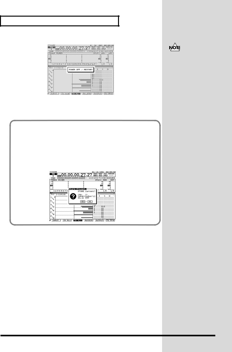
1.Hold [SHIFT] and press [SHUT/EJECT (STOP)]. “SHUTDOWN/EJECT?” message will appear.
Shutdown (Appendices p. 13)
fig.dialog-shutdown
2.Press [ENTER/YES].
3.“STORE Current?” message will appear.
fig.dialog-current store
4.If you wish to store the currently selected project, press [ENTER/YES]. If you do not need to save it, press [EXIT/NO]. However, this display will not appear in the case of a demo performance or if the project is protected (i.e., cannot be edited).
5.When the shutdown procedure ends correctly, the display will indicate “POWER OFF / RESTART” (turn off the power / restart).
Current Project (Appendices p. 12)
For details refer to Owner’s manual Project and Drive Operations –“PROTECT (p. 75)”.
Preparations
23
Preparations
fig.dialog-poweroff
6.Lower the volume of your audio equipment.
7.Turn off the power of your audio equipment.
8.Use the rear panel POWER switch to turn off the VS-2480/2480CD.
If “STORE Current?” is Displayed
When you execute various operations (including Shutdown), “STORE Current?” (Store the current project?) may be displayed. This message asks whether or not you wish to store the currently selected project to disk. If you wish to store the project before continuing with the operation, press [ENTER/YES]. If you do not need to save the project (i.e., if you wish to discard the recording and editing that was done up to that point, and revert to the condition in which the project was last saved), press
[EXIT/NO].
fig.dialog-current store
After the power is turned off, the hard disk will continue rotating for a time due to inertia. During this time, applying physical shock to the VS-2480/2480CD may damage the disk. Before moving a VS-2480/2480CD that contains a hard disk, wait approximately a few seconds after turning off the power.
24

Listening to the Demo Performance
A demo performance needs to be Recovered from CD-ROM of a belonging. Also, the CD-R/RW drive such as the Roland CD Recorder is necessary to the Recover. For details please see the leaflet “To Recover the demo performance” of a belonging.
If you are using a VS-2480 that does not have an internal CD-RW drive, you will need a separately sold CD-RW drive (Roland CD Recorder).
A number of demo performances were placed on the hard disk inside the VS-2480CD before it left the factory.
Using these demo performance for any purpose other than personal enjoyment without permission of the copyright owner is prohibited by law.
How To Load a Demo Song (CD-R Recover)
1.Turn off the power supply of all apparatus.
2.-1. Connect the VS-2480 with the Roland CD Recorder according to “Connecting the CD-R/RW Drive (p. 82)”
-2. Turn on the power of the Roland CD Recorder.
-3. Insert a attached CD in the Roland CD Recorder.
3.Turn on the power of the VS-2480 (rear panel).
4.Press [PROJECT]. Project list appears.
5.Use the TIME/VALUE dial to move the cursor to the drive in which the demo CD-ROM is inserted.
6.Press [F6 (LIST)]. “Change Current Drive?” message appears.
7.Press [ENTER/YES]. “Store Current?” message appears.
8.If you wish to save the current project, press [ENTER/YES]. If not, press [EXIT/NO].
9.Use the TIME/VALUE dial to move the cursor to the demo project that you wish to recover.
10.Press Page 3 [F2 (Recovr)]. Project Recover screen appears.
•CD Speed
Select the speed at which data will be read from a CD-R/RW disc. This parameter will be displayed only if a CD-R/RW drive is selected as the read source.
•Erase All Projects
Off—if you want to add the project(s) you’re recovering to the list of projects already on the destination drive.
On—if you want to clear the drive so it contains only your recovered
In the case of usage, an optional the Roland CD Recorder is required in VS-2480 which do not build in the CD-RW drive.
Demo the to Listening
Performance
25

Listening to the Demo Performance
projects.
11.Select the recovery-destination. Press [F4 (SelDrv)].
Use the TIME/VALUE dial to move the cursor to the recovery-destination, and press [F5 (SELECT)]. If you change your mind about the drive selection, press [F6 (CANCEL)].
12.Press [F5 (OK)]. “Recover from SCSIx Sure?” (x is SCSI ID number) message is displayed.
13.Press [ENTER/YES]. Loading of data starts. If loading finishes, it will return to a home condition screen.
If a disc tray does not open
If the power is turned off with the disc still in the drive (such as due to a power failure), the disc tray cannot be opened by pressing the eject button. In this case, you can insert a piece of wire to force the tray open.
1.Turn off the power of the VS-2480CD.
2.Insert a thin object such as a wire into the emergency eject hole. The disc tray will open.
Emergency Eject Hole
Make sure the VS-2480CD's power has been turned OFF before attempting to use the emergency eject hole. If you insert something while the power is on, the disc could get damaged, or unexpected problems may occur.
26

Listening to the Demo Performance
For Making the Preparations Which Listen to a
Demo Performance (Project Select)
Select a demo song, when you listen to a demo performance. Use the following procedure to select a project.
fig.2-05
1.Press [PROJECT]. Project List screen appears.
2.Use the TIME/VALUE dial to move the cursor to the project that you want to listen to the demo project.
fig.sel-demo_73
3.Press [PAGE] several times until function tab “Page1” will display at the front.
4.Press [F1 (SELECT)]. “Select Project, Sure?” message appears.
5.Press [ENTER/YES]. “STORE Current?” message appears.
EZ |
|
|
|
TRACK EDIT |
|
ROUTING |
COPY |
MOVE |
TRIM IN |
TRIM OUT |
DELETE |
PATCH BAY |
COPY |
MOVE |
INSERT |
CUT |
ERASE |
|
|||||
AUTOMIX |
A.PUNCH |
IN |
OUT |
FROM |
TO |
|
|||||
CD-RW |
MENU |
|
|
MASTERING PROJECT |
TRACK |
EFFECT |
UTILITY |
MIDI / DI
6.If you wish to save the current project, press [ENTER/YES]. If not, press [EXIT/NO].
7.The project will be selected, and you will return to the home condition display.
Using these demo performance for any purpose other than personal enjoyment without permission of the copyright owner is prohibited by law.
The demo projects are protected so that their content cannot be modified (Project Protect) (Owner’s manual p. 48). They cannot be recorded, edited, or stored. If a demo performance or a project for which Project Protect is turned on has been selected, the “STORE Current?” message will not appear, so you can skip step 6.
Demo the to Listening
Performance
27
Listening to the Demo Performance
Playing Back the Demo Performance
fig.02-01_30 |
|
|
|
|
|
|
|
|
|
|
|
|
|
|
|
|
|
|
|
|
|
FROM |
|
|
|
|
|
|
|
|
|
|
|
|
|
|
|
|
|
SOLO |
MUTE |
|
|
|
|
|
|
|
|
|
|
TRACK STATUS // PHRASE PAD |
|
|
|
|
|
|
TR 1-16 |
TR 17-24 |
|
1 |
|||
TO |
|
|
|
|
|
|
|
|
|
|
|
|
|
|
|
|
|
|
FX RTN |
|
|
TRACK |
|
|
|
|
|
|
|
|
|
|
|
|
|
|
|
|
|
|
|
|
|
REC |
|
|
|
|
|
|
|
|
|
|
|
|
|
|
|
|
|
|
V.FADER |
|
|
PLAY |
|
|
|
|
|
|
|
|
|
|
|
|
|
|
|
|
|
MASTER |
|
||
OFF |
|
1 |
2 |
3 |
4 |
5 |
6 |
7 |
8 |
9 |
10 |
11 |
12 |
13 |
14 |
15 |
16 |
EDIT |
|
|
|
PHRASE |
FADER |
|
|
||||||||||||||||||
PAD |
|
|
|
||||||||||||||||||
|
|
17 |
18 |
19 |
20 |
21 |
22 |
23 |
24 |
AUX1MST |
AUX 2 |
AUX 3 |
AUX 4 |
AUX 5 |
AUX 6 |
AUX 7 |
AUX 8 |
MASTER |
|
|
|
|
|
FX1RTN |
FX 2 |
FX 3 |
FX 4 |
FX 5 |
FX 6 |
FX 7 |
FX 8 |
|
|
||||||||||
|
|
|
|
|
|
|
|
|
|
|
|
|
|
||||||||
(dB) |
|
|
|
|
|
|
|
|
|
|
|
|
|
|
|
|
(dB) |
|
|
|
|
R |
6 |
|
|
|
|
|
|
|
|
|
|
|
|
|
|
|
|
6 |
|
R |
|
3 |
4 |
|
|
|
|
|
|
|
|
|
|
|
|
|
|
|
|
4 |
|
|
|
0 |
|
|
|
|
|
|
|
|
|
|
|
|
|
|
|
|
0 |
|
|
|
|
4 |
|
|
|
|
|
|
|
|
|
|
|
|
|
|
|
|
4 |
|
|
|
|
|
|
|
|
|
|
|
|
|
|
|
|
|
|
|
|
|
|
|
|
||
|
8 |
|
|
|
|
|
|
|
|
|
|
|
|
|
|
|
|
8 |
|
|
|
|
12 |
|
|
|
|
|
|
|
|
|
|
|
|
|
|
|
|
12 |
|
|
|
|
18 |
|
|
|
|
|
|
|
|
|
|
|
|
|
|
|
|
18 |
|
|
|
|
24 |
|
|
|
|
|
|
|
|
|
|
|
|
|
|
|
|
24 |
|
|
|
|
42 |
|
|
|
|
|
|
|
|
|
|
|
|
|
|
|
|
42 |
|
|
4,6 |
L |
|
|
|
|
|
|
|
|
|
|
|
|
|
|
|
|
|
|
|
L |
|
|
|
|
|
|
|
|
|
|
|
|
|
|
|
|
|
|
|
|
|
|
|
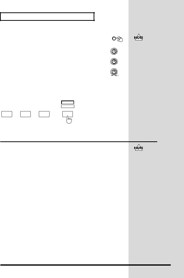
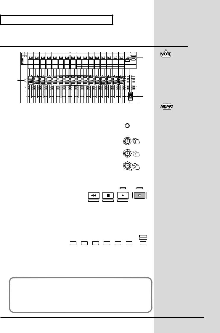
1.Press [TR 1-16 (MASTER EDIT)]. [TR 1-16 (MASTER EDIT)] indicator will light, the channel fader will adjust to the Track Mixer level of channel 1–16.
fig.02-02_50
2.Set the MONITOR knob to the 0 dB position (3 o’clock).
3.Set all channel faders to the 0 dB position.
4.Lower the master fader to the lowest position.
5.Press [PLAY]. The demo performance will play back, and the playback time, level meters, and the playback state of each track (play list) will begin moving.
CONTRAST |
|
||
PHONES 1 |
7 |
||
0 |
10 |
||
|
|||
PHONES 2 |
|
||
0 |
10 |
7 |
|
MONITOR |
|
||
6. Slowly raise the master fader to adjust the volume. The |
2 |
playback time, level masters, and playback status of each track (playlist) etc. will be displayed.
|
fig.02-03 |
|
7. |
To adjust the volume of the |
ZERO |
|
headphones, rotate the PHONES 1 or
STORE
the PHONES 2 knob.
8.When you finish demo performance,
press [STOP]. The demo performance will stop.
STOP |
PLAY |
REC |
SHUT / EJECT |
RESTART |
AUTOMIX REC |
8 |
5 |
|
■ Viewing the Level Meters.
fig.02-04_50
|
|
|
|
|
|
|
|
DISPLAY |
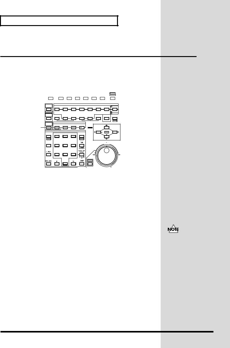
1. |
Press [HOME (DISPLAY)]. |
F1 |
F2 |
F3 |
F4 |
F5 |
F6 |
HOME |
|
|
|
|
|
|
|
||
|
Home Condition screen |
|
|
2 |
|
|
3 |
1 |
|
will appear. |
|
|
|
|
|||
|
|
|
|
|
|
|
|
2.Press [F3 (TR Mix)]. At this time, the level meters will show the volume level of the playback tracks.
Using these demo performance for any purpose other than personal enjoyment without permission of the copyright owner is prohibited by law.
If you set the Track Mixer 17–24, press [TR 17-24/FX
RTN (V.FADER)].
This switches the type of level meters displayed for the function buttons in home condition.
[F1 (INPUT)] |
Levels being input to the input jacks |
[F2 (IN Mix)] |
Levels being input to the input mixer |
[F3 (TR Mix)] |
Track mixer levels |
[F4 (AUXDIR)] |
Signal levels flowing through AUX bus and direct path |
[F5 (OUTPUT)] |
Levels being output to the output jacks |
28
 Loading...