


 Loading...


Table of Contents
1—Welcome to Version Two |
7 |
|
About the VS-2000 Version Two Addendum ............................................................................................................... |
7 |
|
Procedure Descriptions ............................................................................................................................................. |
|
7 |
To Get the Most From Version Two ............................................................................................................................... |
|
8 |
VGA Terminology: The Mixers and the Master Block ................................................................................................ |
8 |
|
2—Version Two Enhancements |
9 |
|
Importing rhythm patterns from SMF (SMF Import) .................................................................................................. |
9 |
|
Cautions concerning import of SMF data .............................................................................................................. |
9 |
|
The SMF IMPORT screen ......................................................................................................................................... |
|
9 |
Importing rhythm patterns from SMF .................................................................................................................. |
|
10 |
Backing Up and Recovering a project via USB ........................................................................................................... |
11 |
|
Data structure of the VS-2000’s internal hard disk ............................................................................................. |
11 |
|
Backing up a project on your computer ............................................................................................................... |
|
13 |
Recovering a backed-up project from your computer ....................................................................................... |
14 |
|
Backing up and Recovering User Rhythm Arranges or Rhythm Patterns ...................................................... |
14 |
|
Added parameters and shortcuts ................................................................................................................................. |
|
15 |
UTILITY Menu System Parameter ........................................................................................................................ |
|
15 |
UTILITY Menu PlayRec Parameter ....................................................................................................................... |
|
15 |
The METRONOME screen ..................................................................................................................................... |
|
15 |
The MASTER EDIT screen ...................................................................................................................................... |
|
16 |
CH PARAMETER LEVEL knob ............................................................................................................................ |
|
16 |
New Shortcuts .......................................................................................................................................................... |
|
16 |
Change in editing method for Rhythm Arrange ........................................................................................................ |
17 |
|
Creating or Editing a Rhythm Arrange ................................................................................................................ |
|
17 |
Using the mouse to input a Rhythm Pattern ....................................................................................................... |
18 |
|
The procedure for editing Harmony has changed ..................................................................................................... |
19 |
|
The HARMONY ASSIGN screen .......................................................................................................................... |
|
19 |
b/# indications have been added .......................................................................................................................... |
|
19 |
Sequencing Harmonies in Step Time .................................................................................................................... |
|
20 |
Audio data waveform display ............................................................................................................................... |
|
20 |
The HARMONY MICRO EDIT screen ................................................................................................................. |
|
21 |
3—Version Two VGA Overview |
23 |
|
The Main Display and the Info Display |
....................................................................................................................... |
23 |
Setting the Operation Target .................................................................................................................................. |
|
23 |
About the Main Display ................................................................................................................................................. |
|
24 |
The LCD as Main Display ....................................................................................................................................... |
|
24 |
The VGA as Main Display ...................................................................................................................................... |
|
24 |
About the Info Display ................................................................................................................................................... |
|
26 |
When the VGA is Designated as the ..............................................................................................Info Display |
26 |
|
When the LCD is Designated as the ...............................................................................................Info Display |
28 |
|
Roland VS-2000 Owner’s Manual, Version Two Addendum |
www.RolandUS.com |
3 |

4—VGA Main Display Universal Elements |
29 |
VGA Menus ...................................................................................................................................................................... |
29 |
The PROJECT Menu ................................................................................................................................................ |
29 |
The TRACK Menu .................................................................................................................................................... |
30 |
The EFFECT Menu ................................................................................................................................................... |
30 |
The UTILITY Menu .................................................................................................................................................. |
31 |
MIXER Menu ............................................................................................................................................................ |
32 |
EZROUTING Menu ................................................................................................................................................. |
32 |
CD-RW MASTERING Menu .................................................................................................................................. |
32 |
RYHTHM TRACK Menu ........................................................................................................................................ |
34 |
VGA Control Bar ............................................................................................................................................................. |
35 |
PAN Knob Strip ............................................................................................................................................................... |
39 |
The VGA Input Clipping Indicators ............................................................................................................................. |
39 |
VGA F Buttons ................................................................................................................................................................. |
39 |
Status Strip ........................................................................................................................................................................ |
40 |
VGA Remaining Space Status Strip .............................................................................................................................. |
40 |
5—VGA Main Display Home Screen |
41 |
The Meters Strip .............................................................................................................................................................. |
41 |
Working with the Meters Strip ............................................................................................................................... |
42 |
The Playlist Area ............................................................................................................................................................. |
44 |
Operating the VGA Playlist .................................................................................................................................... |
44 |
VGA Playlist Track Controls .................................................................................................................................. |
46 |
The Playlist’s Measure Bar ...................................................................................................................................... |
50 |
Editing VGA Playlist Track Audio ........................................................................................................................ |
51 |
The VGA Playlist Control Panel ............................................................................................................................ |
53 |
The VGA Wave Display .......................................................................................................................................... |
55 |
6—VGA Main Display CH VIEW Screens |
57 |
Displaying CH EDIT Parameters on the VGA ............................................................................................................ |
57 |
Universal CH VIEW Elements ....................................................................................................................................... |
58 |
Input/Output Control Strip ................................................................................................................................... |
58 |
AUX and FX Send Controls .................................................................................................................................... |
59 |
DIR (DIRECT) 1-8 Selector ...................................................................................................................................... |
60 |
Channel-Specific Parameter Strips ................................................................................................................................ |
60 |
Input Channel Parameter Strip .............................................................................................................................. |
60 |
Track Channel Parameter Strip .............................................................................................................................. |
61 |
FX Return Channel Parameter Strip ...................................................................................................................... |
62 |
Input and Track Channel CH VIEW Elements ........................................................................................................... |
63 |
Track/V-Track Info .................................................................................................................................................. |
63 |
Dynamics and EQ Controls .................................................................................................................................... |
63 |
EFFECT INSERT Controls ...................................................................................................................................... |
66 |
FX Return Channel CH VIEW Elements ...................................................................................................................... |
67 |
LOOP FX ASSIGN .................................................................................................................................................... |
67 |
Effect Algorithm Display ........................................................................................................................................ |
67 |
4 |
www.Roland.com |
Roland VS-2000 Owner’s Manual, Version Two Addendum |

7—Mixer Views |
69 |
|
Shared Elements .............................................................................................................................................................. |
|
69 |
Shared MASTER Fader Strip .................................................................................................................................. |
69 |
|
AUX and FX Send Sliders ....................................................................................................................................... |
70 |
|
Input Mixer/Master Block View .................................................................................................................................. |
71 |
|
Input Channel Strips ............................................................................................................................................... |
71 |
|
Master Block Strips |
.................................................................................................................................................. |
72 |
Track Mixer/FX Return Mixer View ............................................................................................................................ |
74 |
|
Track Channel Strips ............................................................................................................................................... |
74 |
|
FX Return Channel Strips ....................................................................................................................................... |
76 |
|
8—VGA Main Display EZ ROUTING Screen |
77 |
Making Connections ....................................................................................................................................................... |
77 |
Routing on the VGA Using a Mouse .................................................................................................................... |
77 |
Recording Bus Attenuation ........................................................................................................................................... |
78 |
9—VGA Main Display Automix Editing |
79 |
|
Editing Automix Data on the VGA .............................................................................................................................. |
79 |
|
|
Targeting Automix Tracks and Data for Editing ................................................................................................ |
80 |
Index |
81 |
|
Roland VS-2000 Owner’s Manual, Version Two Addendum |
www.RolandUS.com |
5 |

6 |
www.Roland.com |
Roland VS-2000 Owner’s Manual, Version Two Addendum |

1—Welcome to Version Two
The VS-2000 Version Two Addendum is a companion to the VS-2000 Owner’s Manual and describes the features of the Version 2.00 operating system for the VS-2000.
About the VS-2000 Version Two Addendum
Throughout the Addendum, we’ll refer to both V-Studios as the“VS-2000” to make things simpler. Unless otherwise noted, everything in the Addendum applies equally to the VS-2000.
Though many ofVersion Two’s new features involve the use of an externalVGA display, it also adds new capabilities to theVS-2000 itself.These are described in the Addendum’s second chapter,“Version Two Enhancements.” The remaining chapters discuss Version Two’s VGA display-related features—these chapters assume you’ve connected a color VGA display and configured it for use.
Since most VGA display features are also found on the VS-2000 itself, the VS-2000 Owner’s Manual already contains descriptions of how they work. When the Owner’s Manual explains how a VGA feature works, we’ll point you to the relevant page or pages. We’ll do this in either of two ways:
•When groups of items are presented in lists, their Owner’s Manual pages will be shown at their right.
• In other cases, we’ll use the double-arrow symbol shown here. In |
123 |
|
|
this example, we’d be directing you to Page 123. |
|
Procedure Descriptions
Most of the VS-2000’s operations can be performed from its top panel or the VGA display.You’ll often be able to, for example, use a button by pressing it on the VS-2000 or by clicking it with your mouse on the VGA or the VS-2000’s LCD.You could also set a level by moving a channel strip fader or by dragging your mouse.
When we refer to the“LCD,” we’re referring to the VS-2000’s own, built-in LCD. To avoid confusion, bear this in mind if your external VGA display is also an LCD.
For the sake of simplicity, certain sections of the Addendum describe actions as if you’re working the VS-2000’s top-panel controls. As you follow these steps, bear in mind that in many cases you can just as easily use your mouse on the VGA or the VS-2000’s LCD. The same applies to most of the operations described in the VS-2000 Owner’s Manual.
Roland VS-2000 Owner’s Manual, Version Two Addendum |
www.RolandUS.com |
7 |

1—Welcome to Version Two
To Get the Most From Version Two
Connect an optional color VGA display to the VS-2000 to take full advantage of Version Two’s capabilities. WithVersion Two, theVS-2000 offers the power and convenience of a computer-based DAW (“digital audio workstation”) and dedicated control surface with none of the setup, configuration or maintenance difficulties.
To learn about connecting, setting up and configuring a VGA display and/or ASCII keyboard, see Pages 64 and 66 of the VS-2000 Owner’s Manual.
If you’d prefer to use your VS-2000 without a VGA display, make sure that the UTILITY menu’s OPERATION TARGET parameter is set to LCD. See “Setting the Operation Target” on Page 23.
VGA Terminology: The Mixers and the Master Block
The VS-2000 contains a powerful 40-channel mixer that has dedicated input, track, and FX return channels—all of these channels are always active and available. See Page 52 of the VS-2000 Owner’s Manual for a description of what these channels do.
To help navigate its menus and screens, the VGA display treats the various channel types as if they belong to separate mixers. These are the:
•Input Mixer—which contains all 10 of the VS-2000’s input channels.
•Track Mixer—which contains all 18 of the VS-2000’s track channels.
•FX Return Mixer—which contains all six of the stereo FX return channels.
In addition, the two Aux and six FX send master channels are grouped together with the MASTER EDIT Aux and FX bus and Direct path configuration settings as the “Master Block.”
While we use these terms to make getting around onscreen easier, it’s important to remember that they’re not really separate mixers. They’re all just sections of the VS-2000’s single massive 40-channel mixer. Therefore, viewing one of these“mixers” doesn’t de-activate any of the others—it just makes the selected mixer visible.
8 |
www.Roland.com |
Roland VS-2000 Owner’s Manual, Version Two Addendum |

2—Version Two Enhancements
This chapter describesVersion Two enhancements that add new features to theVS-2000. These new features can be used from the VS-2000 LCD or a VGA display. Chapter 3 describes choosing the display on which you want to work.
Importing rhythm patterns from SMF (SMF Import)
SMF (Standard MIDI File) data from a CD-ROM or CD-R/RW can be imported as rhythm patterns (SMF Import).
Cautions concerning import of SMF data
•Data can be imported only from ISO9660 format CD-ROM or CD-R/RW discs.
•A maximum of eight measures can be loaded from the SMF, starting at the location you specify.
•SMF Format 0 or Format 1 data can be loaded.
•Depending on the SMF data, there may be drum sounds that are not played by the internal PCM sound generator. By using an external MIDI sound module you can play the drum sounds corresponding to each note number (Owner’s Manual Page 321).
The SMF IMPORT screen
1.Insert a CD containing SMF data into your CD-R/RW drive.
2.Navigate to the RHYTHM PATTERN SETUP screen (Owner’s Manual Page 314).
3.If“SMFImp” isn’t visible above F3, press the PAGE button so it is.
4.Press F3 (SMFImp)—the SMF IMPORT screen appears.
This screen presents you a list of all of the SMF and folders in the CD’s currently selected directory.You can select any item in the list by using " and # or the Time/ Value dial to highlight it.
Each file directory on the CD appears in the displayed list as a folder. To open a folder, select it and press F5 (ChgDir) for“Change Directory.” When you’re inside a folder, an upward arrow points you back to the folder’s parent directory.To move up and back out of the folder, highlight“<<Parent Directry>>” and press F5 (ChgDir) again.
The list provides information about each of its SMF. This column can show you each file’s:
•Size—indicates the file size (in bytes).
•Date/Time—indicates the date and time at which the file was last modified.
Roland VS-2000 Owner’s Manual, Version Two Addendum |
www.RolandUS.com |
9 |

2—Version Two Enhancements
Importing rhythm patterns from SMF
The SMF data is imported into the current rhythm pattern. However, you need to remember that the imported rhythm pattern is temporary. If you select another rhythm pattern or turn off the power before saving the imported rhythm pattern, it will be lost. If you want to keep a rhythm pattern that you imported using the SMF Import function, you must save it as a Project Rhythm Pattern or as a User Rhythm Pattern (Owner’s Manual Page 319).
1.Insert a CD containing SMF data into your CD-R/RW drive.
2.Navigate to the RHYTHM PATTERN SETUP screen (Owner’s Manual Page 314).
3.If“SMFImp” isn’t visible above F3, press the PAGE button so it is.
4.Press F3 (SMFImp).
5.Highlight the SMF you want to import.
6.Press F5 (SELECT)—the SMF Import parameter screen appears.
To return to the SMF IMPORT screen, press F1 <<BACK). To abort the procedure, press F6 (EXIT).
In the SMF IMFORMATION area shows information about the SMF you selected in the SMF IMPORT screen.
•NAME—file name
•FORMAT—SMF format. SMF Format 0 or Format 1 data can be imported.
•TRACKS—number of tracks
•BEAT—time signature
•TPQN (Ticks Per Quarter Note)—smallest unit of time in the SMF (the resolution per quarter note)
7.In the IMPORT PARAMETER area, you can specify the data that will be imported from the SMF as a rhythm pattern. Set the parameter to:
•TRACK—select the track that you want to import.
•CHANNEL—select the channel that you want to import.
•MEASURE—specify the measure from which you want to start importing.
•LENGTH—specify the number of measures (length) that you want to import.
8.Press F5 (OK) to import the SMF into the current rhythm pattern.
9.When SMF import is completed, the Rhythm Pattern Setup screen appears.
10 |
www.Roland.com |
Roland VS-2000 Owner’s Manual, Version Two Addendum |
2—Version Two Enhancements
Backing Up and Recovering a project via USB
The following operations have been added. When connected with computer via USB, you can:
•Backing up and Recovering VS-2000’s project
•Backing up and Recovering VS-2000’s user rhythm arrange or rhythm pattern
 Important
You must carefully read“Caution when using USB Storage Mode” (Owner’s Manual Page 81) together with this chapter, and perform this procedure as directed. Roland Corporation accepts no responsibility for any loss of data or malfunction of theVS-2000 caused by incorrect operation. Nor will Roland accept responsibility for recovering any lost hard disk content nor any damages that may result from such loss.
Data structure of the VS-2000’s internal hard disk
VS-2000 icons
When USB Storage mode starts up and the internal hard disk of the VS-2000 has been detected by your computer, one or more“VS-2000 icons” will appear.
Each VS-2000 corresponds to a partition. Up to four partitions (IDE:0–IDE:3) will be detected in order of the partition number.
•Windows ME/2000/XP
The VS-2000 icon(s) will be added to“My Computer.”
[Example] Windows 2000
The drive letter (the alphabetical name of the drive) will depend on your computer system.
•Mac OS 10.2 or later
The VS-2000 icon(s) will be added to the desktop.
Roland VS-2000 Owner’s Manual, Version Two Addendum |
www.RolandUS.com |
11 |

2—Version Two Enhancements
VS-2000 internal hard disk data structure
When you click a VS-2000 icon, the files and folders of the VS-2000’s internal hard disk (partition) will be displayed on your computer.
These files and folders are organized as follows.
/ (root)
SONG0001.VS2
Project folder
SONG0002.VS2
Project folder
* A separate folder is created for each project.
PORT used to recover a data backed up
PORT on your computer.
AMIXPCTL.VS2
Automix pattern data file
PRJRHARR.VS2
Project rhythm arrangement file
PRJRHPAT.VS2
Project rhythm pattern file
USRRHARR.VS2
User rhythm arrangement file
USRRHPAT.VS2
User rhythm pattern file
SONGLIST.VS2
Project list file
SYSTEM.VS2
System data file
TMPAMX0.VS2
Automix data 0 file
TMPAMX9.VS2
Automix data 9 file
TMPSCENE.VS2
Scene file
You can back up the following folders and files.
Never copy/move/rename/delete any folders or files other than those listed below. Doing so will render the VS-2000 system unable to function correctly, and may also result in the loss of your valuable data. Roland cannot guarantee that the VS-2000 will operate if you manipulate any folders or files other than the following.
•SONGxxxx.VS2 folder—These folders contain the project data.You must back up the entire folder.
•USRRHPAT.VS2 file—This is the user rhythm pattern data.
•USRRHARR.VS2 file—This is the user rhythm arrangement data.
12 |
www.Roland.com |
Roland VS-2000 Owner’s Manual, Version Two Addendum |

2—Version Two Enhancements
Backing up a project on your computer
You must not rename or rewrite the folders or files backed up to your computer. Doing so will make it impossible to recover the data correctly.
1.Start up USB Storage Mode as described in“Establishing a connection to your computer” (Owner’s Manual Page 82). After a time, your computer will detect the VS-2000’s internal hard disk.
2.As described in “VS-2000 icons” on Page 11, double-click the VS-2000 icon for the partition that contains the project you want to back up. The files and folders on the VS-2000’s internal hard disk will be displayed.
[Example] Windows 2000
<< Project and folder names >>
The data for each project is saved in a separate folder named “SONGxxxx.VS2”.
The “xxxx” portion of the folder name will be a number in the order of the projects shown in the project list.
3.Copy the entire folder“SONGxxxx.VS2” for the project you want to back up onto the hard disk of your computer. The project data will be copied to your computer.
[Example] Windows 2000
Copy the entire “SONGxxxx.VS2” folder.
4.Exit USB Storage Mode as described in“Terminating the connection to your computer” (Owner’s Manual Page 84).
Roland VS-2000 Owner’s Manual, Version Two Addendum |
www.RolandUS.com |
13 |

2—Version Two Enhancements
Recovering a backed-up project from your computer
1.Start up USB Storage Mode as described in“Establishing a connection to your computer” (Owner’s Manual Page 82).
2.As described in “VS-2000 icons” on Page 11, double-click the“VS-2000 icon” for the recovery-destination partition (i.e., the partition to which you will be recovering the project). The folders and files in the VS-2000’s internal hard disk will be displayed.
3.Copy the entire backed-up folder into the“PORT folder.”
Before copying the backed-up project into the “PORT folder,” you must disable the “read-only” attribute from the folder and the files it contains.
The backed-up project will be recovered into the VS-2000’s internal hard disk.
[Example] Windows 2000
Copy the entire backed-up “SONGxxxx.VS2 folder” into the “PORT folder.”
4.Exit USB Storage Mode as described in“Terminating the connection to your computer” (Owner’s Manual Page 84).
5.Access the Project List screen (Owner’s Manual Page 99), and verify that the Recover operation was successful. The recovered project will be added at the end of the project list in the recover-destination partition.
Backing up and Recovering User Rhythm Arranges or Rhythm Patterns
You can back up and recover user rhythm arrangements and patterns in the same way as when backing up and recovering a project. Simply back up and restore the following files.
•USRRHPAT.VS2 file (User rhythm patterns)
•USRRHARR.VS2 file (User rhythm arrangements)
User Rhythm Arrangement/Pattern data files are shared by all projects in the partition. Be aware that when you recover these files, the existing user rhythm arrangement/ pattern data files will be overwritten.
14 |
www.Roland.com |
Roland VS-2000 Owner’s Manual, Version Two Addendum |

2—Version Two Enhancements
Added parameters and shortcuts
UTILITY Menu System Parameter
DYNAMICS/4Bnd EQ Sw parameter has been added on the Param1 screen of the UTILITY menu’s System parameter. This selects the screen that appears in the LCD display when you press DYNAMICS or EQ.You can set the parameter to:
• Dynm/EQ—the Dynamics or Equalizer screen for the current channel appears.
•Ch VIEW—the Mixer View screen for the current channel will appear.
In the VGA display, the Mixer View screen for the current channel is always displayed.
UTILITY Menu PlayRec Parameter
FX Rtn SOLO ENABLE parameter has been added on the Param1 screen of the UTILITY menu’s PlayRec parameter. This specifies solo setting of EX return channels.You can set the parameter to:
•On—channel 1-6 of FX return will be automatically soloed subject that solo of Input or Track channel is turned on.
•Off—no channel of FX return will be automatically soloed. Solo must be manually set selecting channel of FX return.
This setting is valid if SOLO/MUTE TYPE PlayRec parameter is set to All BUS Send.
The METRONOME screen
OUTPUT SELECT parameter has been added on the METRONOME screen (Owner’s Manual Page 308). When you set METRONOME OUT parameter to INT, this field selects the output jack(s) and a digital connector from which the metronome sound will be output. The metronome sound will be output from the jack(s) whose check box is selected.
Roland VS-2000 Owner’s Manual, Version Two Addendum |
www.RolandUS.com |
15 |

2—Version Two Enhancements
The MASTER EDIT screen
Function button F4 (FX RTN) has been added (the LCD display only). Press F4 (FX RTN) the FX return Parameter View screen (Owner’s Manual Page 231). When this screen appear, the FADER parameter is displayed as default.
CH PARAMETER LEVEL knob
You can use the CH PARAMETER Level knob to adjust the Ratio of the DYN parameter (Owner’s Manual Page 167).
CH PARAMETER Knob: |
Expander parameter: |
Compressor parameter: |
|
|
|
LEVEL knob |
Ratio |
Level |
New Shortcuts
A variety of new shortcuts have been added in Version Two.
Hold down: |
To: |
|
|
CLEAR and press CH EDIT |
switches the UTILITY menu’s Rtn TO Tr STATUS |
|
Sw on/off parameter (Owner’s Manual Page 379). |
|
|
CLEAR and |
When the CH EDIT VIEW screen or the Parameter |
turn the TIME/VALUE dial |
View screen is displayed, this edits the following |
|
parameters for each mixer. |
In addition, when the CH EDITVIEW screen or the ParameterView screen is displayed:
Hold down: |
To: |
CLEAR and
turn the TIME/VALUE dial
edits the following parameters for each mixer.
•Track Mixer—V-TRACK, MIX Switch, SOLO Switch, MUTE Switch
•Input Mixer—MIX Switch, SOLO Switch, MUTE Switch
•Effect return Mixer—MIX Switch, SOLO Switch, MUTE Switch
The mixer channel that is edited will be the mixer for the current channel.You will need to select the parameters that will be affected.
16 |
www.Roland.com |
Roland VS-2000 Owner’s Manual, Version Two Addendum |

2—Version Two Enhancements
Change in editing method for Rhythm Arrange
The Rhythm Arrange editing method has been changed in VS-2000 system version 2.0. The procedure described below replaces the section“Creating or Editing a Rhythm Arrange” (Owner’s Manual Page 309).
The F buttons in the RHYTHM ARRANGE EDIT screen have also been moved. The F buttons have been moved as follows.
In Version One:
In Version Two:
If you’re looking for an screen whose F button is currently hidden, press PAGE repeatedly until its F button appears.
Creating or Editing a Rhythm Arrange
Creating and editing a rhythm arrange are really the same process, since you always start with the currently selected rhythm arrange.
Temporary Rhythm Arrange Memory
When you modify a rhythm arrange, it’s automatically copied into a special area of temporary memory within theVS-2000. Any changes to make to the rhythm arrange are made to this copy. Its name changes to“TEMP” to show this. When you’re satisfied with your work, save the rhythm arrange in the user or project Rhythm Track memory.
Once you begin editing an existing rhythm arrange, the VS-2000 holds it in a special temporary memory area—the display shows“TEMP” at the front of the rhythm arrange’s name. To avoid losing your work, save the rhythm arrange to user or project memory before selecting a different rhythm arrange or turning off the VS-2000. See “Saving a Rhythm Arrange” on Owner’s Manual Page 311.
1.Press RHYTHM TRACK to display the RHYTHM TRACK screen.
2.To create a new rhythm arrange from scratch, select USER 1—Empty Arrange.
Otherwise, select the rhythm arrange you wish to edit.
3.Press F2 (EDIT) to display the RHYTHM ARRANGE EDIT screen.
|
|
|
|
|
RHYTHM PATTERN |
Information about |
|
|
area |
||
|
|
ARRANGE EDIT |
|||
the rhythm pattern |
|
|
area |
||
assigned to the |
|
|
|
||
current measure is |
|
|
|
|
|
shown. |
|
|
|
||
4.If you’re creating a new rhythm arrange, press " to highlight MEASURE and turn the Time/Value dial to Measure 1. If you’re editing a rhythm arrange, select a measure whose rhythm pattern you wish to change.
Roland VS-2000 Owner’s Manual, Version Two Addendum |
www.RolandUS.com |
17 |

2—Version Two Enhancements
5.Press # to highlight the Group parameter and select the type of pattern you wish to use at Measure 1.
6.Select the specific pattern you want to use by setting the No. value.
The selected rhythm pattern’s name appears beneath the Group and No. parameters. To the right of its name is the pattern’s nominal length.
You can press F1 (Previw) to select rhythm pattern preview mode; the selected rhythm pattern will play repeatedly. If“Previw” isn’t visible above F1, press the PAGE button so it is. To exit preview mode, press F1 (Previw) once again.
7.You can selected one of two modes when you input Rhythm Pattern in the ARRAGEN EDIT area. If“Overwr” or“INSERT” doesn’t appear above F2 or F3, press the PAGE button once. Then press F2 (Overwr) or F3 (INSERT). Press:
•F2 (Overwr)—The rhythm pattern at the“MEASURE” location will be overwritten.
•F3 (INSERT)—The number of measures (length) of the selected rhythm pattern will be inserted at the“MEASURE” location. The rhythm patterns assigned to subsequent measures will not be overwritten.
8.Adjust the LENGTH value as desired—as you do so, you see the pattern’s size change to reflect the LENGTH value.
Pattern boxes |
Box—Indicates the same rhythm pattern. |
|
Dotted lines within box—Indicate locations at |
|
|
|
which the rhythm pattern will repeat. |
|
|
9.Set MEASURE to the next project section to set up, and repeat Steps 5-8.
Here’s a quick formula that tells you the next measure to be programmed when you’re creating a new pattern from the top. Add the MEASURE value to the LENGTH value— the total is the next measure you need to work on.
When you’re programming a rhythm arrange, you can increase the MEASURE value using the FF button, or decrease it by pressing the REW button.
10.Repeat Step 9 until you’ve finished creating or editing the rhythm arrange.
11.Save you work before selecting a new rhythm arrange or turning off the VS-2000. See“Saving a Rhythm Arrange” on Owner’s Manual Page 311.
Using the mouse to input a Rhythm Pattern
When step-recording a rhythm pattern (Owner’s Manual Page 317), you can use a mouse to input drum sounds as follows.
In the pattern editing grid, move the mouse pointer to the desired drum sound and input location so that the pointer changes to the“  ” shape, and click.
The velocity value of the drum note will change as follows each time you click.
using mouse: |
the velocity value changes: |
|
||
|
|
|
|
|
Left-click |
None (blank) → |
25 → |
50 → |
75 → 100 → 127 |
|
|
|
|
|
Right-click |
127 → 100 → 75 → |
50 → |
25 → |
None (blank) |
18 |
www.Roland.com |
Roland VS-2000 Owner’s Manual, Version Two Addendum |

2—Version Two Enhancements
The procedure for editing Harmony has changed
The HARMONY ASSIGN screen
OFF (Use No FX) can be selected under USE EFFECT BOARD parameter.You can visually confirm whether harmony is turned on or off.
b/# indications have been added
If TRACK/STATUS button 12 (b/#) is pressed,“b” or“#” symbols are now displayed in the HARMONY REALTIME RECORD screen and HARMONY STEP EDIT (NOTE) screen.
Roland VS-2000 Owner’s Manual, Version Two Addendum |
www.RolandUS.com |
19 |

2—Version Two Enhancements
Sequencing Harmonies in Step Time
Event list
TARGET Parameter has been added
TARGET parameter has been added on the HARMONY STEP EDIT (NOTE) screen (Owner’s Manual Page 339).You can now specify the harmony part and input note events.You can select:
•NOTE—The harmony part is assigned automatically.
•NOTE 1–NOTE 6—Directly specify the harmony part 1–6. NOTE 1–NOTE 6 correspond to harmony parts 1–6.
New Event List Display
Note events (boxes) other than the harmony part specified by“TARGET” are displayed in light gray.
Audio data waveform display
In the screens listed below, the WAVE area now always displays the audio data waveform for the harmony source track. In conjunction with this change, the F button F1 (WAVE) which switched the WAVE area waveform display on/off has been eliminated.
•HARMONY REALTIME RECORD screen
•HARMONY STEP EDIT (NOTE) screen
•HARMONY MICRO EDIT screen
20 |
www.Roland.com |
Roland VS-2000 Owner’s Manual, Version Two Addendum |
2—Version Two Enhancements
The HARMONY MICRO EDIT screen
EVENT: NOTE 1–NOTE 6 have been added
You can now specify the harmony part (1–6) of note events as follows:
•NOTE—The harmony part is assigned automatically.
•NOTE 1–NOTE 6—Directly specify the harmony part 1–6. NOTE 1–NOTE 6 correspond to harmony parts 1–6.
Val1: Note pitch editing
In the Harmony Micro Edit screen, you can now edit“Val1: pitch” of note events.
If editing“Val1: pitch” causes an overlap with an existing note event, a“Note event overlaps! Overwrite?” dialog appears. Press ENTER/YES, the existing note event is overwritten. To cancel, press EXIT/NO.
Roland VS-2000 Owner’s Manual, Version Two Addendum |
www.RolandUS.com |
21 |

2—Version Two Enhancements
22 |
www.Roland.com |
Roland VS-2000 Owner’s Manual, Version Two Addendum |
3—Version Two VGA Overview
The Main Display and the Info Display
Whenever an external VGA monitor is connected, the VS-2000 provides a main display and an Info Display. The:
•main display—is where you work.You can interact with the main display using your mouse, keyboard and the VS-2000’s top-panel controls. All messages appear here.
•Info Display—is a non-interactive screen that provides helpful supplemental information. Page 26 describes how to determine the contents of the Info Display.
You can select the VGA display or the LCD display as the main display, but not both at the same time. When you select the main display—by setting the OPERATION TARGET parameter—the other display is automatically designated as the Info Display.
Setting the Operation Target
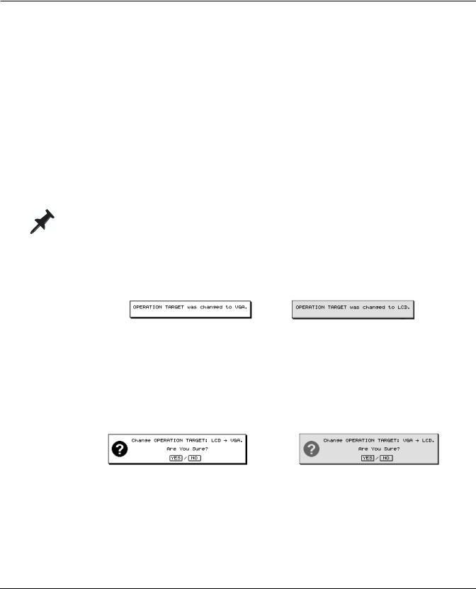
The VS-2000 displays the currently selected operation target when it powers up.
•You can toggle between the two OPERATION TARGET settings—VGA or LCD—by
holding down HOME and pressing the LCD↔ VGA button. Each time you reset the OPERATION TARGET, the previously selected main display confirms the change.
The internal LCD shows: The external VGA shows:
•You can manually set the OPERATION TARGET parameter as described below.
Manually Setting the OPERATION TARGET Parameter
1.Hold down SHIFT and press F4 (UTIL).
2.If“SYSTEM” isn’t visible above F1, press PAGE until it is.
3.Press F1 (SYSTEM).
4.Press F2 (Param3) and locate the OPERATION TARGET parameter.
5.Set OPERATION TARGET to VGA or LCD. On the main display, the VS-2000 asks:
or
6.Press ENTER/YES to proceed, or EXIT/NO to cancel the change.
Roland VS-2000 Owner’s Manual, Version Two Addendum |
www.RolandUS.com |
23 |

3—Version Two VGA Overview
About the Main Display
The LCD as Main Display
When the LCD is designated as the main display, it behaves as described in the VS-2000 Owner’s Manual.
The VGA as Main Display
With a connected external VGA display, your mouse and keyboard become your main tools and the VS-2000 acts as a full-featured control surface. Its faders, knobs and buttons provide a great way to physically interact with what’s on the VGA display:
•You can select channels and parameters on the VGA with your mouse, and change their settings using the VS-2000’s faders or knobs if you wish.
•You can use the VS-2000’s transport buttons (Owner’s Manual Page 175) to operate the hard disk recorder as you view your project on the VGA display.
•You can select audio or other data on theVGA using your mouse, and perform edits instantly by pressing the appropriate button on the VS-2000.You can undo any edit using the top panel’s UNDO•REDO button or its onscreen counterparts.
•You can use the VS-2000’s LCD as an secondary display on which you can keep important information in view as you work on the VGA.
Of course, there’s no single“correct” way to use all of the VS-2000’s available tools— odds are you’ll intuitively develop the easiest, fastest way to work for your needs.
Areas of the VGA Main Display
When the VGA acts as the main display, it’s comprised of several different areas, described in detail in the following chapters.
HOME button
Menus and control bar
PAN knob strip and clipping indicators
Meters strip
Content pane
F buttons, status strip and remaining space status strip
On the VGA main display Home screen—shown here—the lower pane contains the project playlist, described in Chapter 5.
24 |
www.Roland.com |
Roland VS-2000 Owner’s Manual, Version Two Addendum |

3—Version Two VGA Overview
Some of these areas are always available and some change, as described later in the
Addendum:
•Menus, control bar, F buttons, status strip and remaining space status strip—are always visible on the VGA. See Chapter 4.
•PAN knob strip and clipping indicators—are always visible on the VGA. See Chapter 4.
•The meters strip—shows the currently selected level meters. See Chapter 5.
•Content pane—the contents of this area change as described in Chapters 5-8.
The VGA’s Main Display Home Screen
Like the LCD, the VGA main display has its own Home screen, shown on the previous page.You can return to the Home screen at any time by clicking the HOME button in the upper right-hand corner of the display (as shown on Page 24), the HOME button on the VS-2000 or the Home button on your keyboard.
Button Colors on the VGA Main Display
The VGA contains a wide assortment of on/off switches, presented as clickable buttons. Unless otherwise noted, when a button is switched on, it turns yellow—when it’s off, it’s gray.
The transport REC button and the Mastering Room and Automix Record buttons behave a little differently: they turn red when activated.
Gray |
|
|
|
|
|
|
Off |
|
|
|
|
|
|
||||
Yellow |
|
|
|
|
|
|
On |
|
|
|
|
|
|
||||
Gray |
|
|
|
|
|
Off |
||
|
|
|
|
|
||||
|
|
|
||||||
|
|
|
|
|
||||
Red |
|
|
|
|
|
On |
||
|
|
|
|
|
||||
|
|
|
|
|
|
|
|
|
Interaction with the VS-2000’s Top-Panel Controls
The VS-2000’s top-panel buttons generally interact with the currently selected main display as described in the VS-2000 Owner’s Manual. When the VGA is selected as the main display, however, there are a few minor differences:
•Hold down SHIFT and press F1 (PROJ), F2 (TRACK), F3 (EFFECT) or F4(UTIL) button on the VS-2000 to display the corresponding menu on the VGA. To close a menu, press EXIT/NO.
•The Home screen’s fader/pan buttons determine what’s displayed in the lower part of the screen. Press:
•IN F/P—to display the Input Mixer and Master Block.
•TR F/P—to display the Track Mixer and FX Return Mixer.
Sub-Windows
In some cases, when you click a button on theVGA main display or select a menu item, a window opens that looks just like the corresponding screen on the VS-2000’s LCD, with the same F buttons available at the bottom of the window. The contents of the window behave the same way they do on the VS-2000’s LCD.You can exit the screen by clicking the box in its upper-left corner or by pressing F6 (EXIT).
Roland VS-2000 Owner’s Manual, Version Two Addendum |
www.RolandUS.com |
25 |

3—Version Two VGA Overview
About the Info Display
You can choose what you’d like to see on the Info Display using the PAGE and F buttons (see Owner’s Manual Pages 69 and 68).You can press these buttons on the VS-2000 or click them on the VGA display.
When the VGA is Designated as the Info Display
Most of the VGA Info Display’s screens are divided into four areas.
 VGA control bar
 PAN knob strip
Meters strip
Bottom pane
The Info Display also provides a date and time readout in its upper right-hand corner.
VGA Control Bar
The VGA control bar is described in Chapter 4, starting on Page 35.
PAN Knob Strip
PAN select button
Clipping indicators
PAN knob settings
This strip shows the input or track channels’ current PAN settings. Click one of the PAN select buttons at upper left of the trip, you can switch display of the PAN parameter. To the right of the strip are input clipping indicators that show when a channel’s input signal level is too loud.
Meters Strip
In certain display modes—see “Selecting Info Displays Manually” below—the meters strip shows the set of meters currently selected on the Home screen.
|
|
|
|
|
|
|
|
Meters for the |
|
|
|
|
|
|
|
|
MONITOR and |
|
|
|
|
|
|
|
MASTER busses |
|
|
Currently selected meters |
|
||||||
26 |
www.Roland.com |
Roland VS-2000 Owner’s Manual, Version Two Addendum |

3—Version Two VGA Overview
Bottom Pane
The contents of the Info Display’s bottom pane changes from screen to screen.
Controlling What’s On the Info Display
As you navigate the VS-2000’s LCD display, the Info Display automatically switches between various screens.You can manually switch to a few key screens, and you can lock the display so that it doesn’t change as you move around on the VS-2000.
Selecting Info Displays Manually
You can access several key screens from the VS-2000’s Home screen.
1.Press HOME.
2.Press PAGE until“ID PL” appears above the F1 button.
3.You can press F1 through F5 to view the following screens:
•ID PL (Info Display Playlist screen)—shows the track playlist in the lower area on the display.
•ID IN (Info Display Input Channels)—shows all 10 input channels in the lower area on the display.
•ID TR (Info Display Track Channels)—shows all 18 track channels in the lower area on the display.
•ID ChV (Info Display Channel View)—shows the CH EDIT parameters for the currently selected input, track or FX return channel.
When the ID PL, ID IN or ID TR screens are in view, the meters strip is visible.You can change what’s shown on the left side of the meters strip—the right side always shows the MONITOR and MASTER output levels:
1.Press HOME.
2.Press PAGE until INPUT appears above F1.
3.Press:
•INPUT—to meter the VS-2000’s analog and digital input jacks and connectors.
•IN Mix—to meter input channel levels.
•TR Mix—to meter track channel levels.
•AUXDIR—to meter the AUX and DIR bus levels.
•OUTPUT—to meter the VS-2000’s output levels.
Locking the Info Display
You can lock the currently displayed Info Display screen so that it stays in view as you move from screen to screen on the VS-2000 itself.
1.Press HOME.
2.Press PAGE until“IDHold” appears above the F6 button.
3.Press F6 (IDHold).
4.To unlock the display, repeat Steps 1-3.
Roland VS-2000 Owner’s Manual, Version Two Addendum |
www.RolandUS.com |
27 |
Loading...