


 Loading...
Model PR-C1
Machine Code: (D010)
SERVICE MANUAL
Feb. 19th, 2007
Subject to change

Safety Notices
Important Safety Notices
Prevention of Physical Injury
1.Before disassembling or assembling parts of the copier and peripherals, make sure that the copier power cord is unplugged.
2.The wall outlet should be near the copier and easily accessible.
3.If any adjustment or operation check has to be made with exterior covers off or open while the main switch is turned on, keep hands away from electrified or mechanically driven components.
4.The copier drives some of its components when it completes the warm-up period. Be careful to keep hands away from the mechanical and electrical components as the copier starts operation.
5.The inside and the metal parts of the fusing unit become extremely hot while the copier is operating. Be careful to avoid touching those components with your bare hands.
Health Safety Conditions
1.Toner and developer are non-toxic, but if you get either of them in your eyes by accident, it may cause temporary eye discomfort. Immediately wash eyes with plenty of water. If unsuccessful, get medical attention.
2.This machine, which uses a high voltage power source, can generate ozone gas. High ozone density is harmful to human health. Therefore, the machine must be installed in a well-ventilated room.
Observance of Electrical Safety Standards
This machine and its peripherals must be serviced by a customer service representative who has completed the training course on those models.
•Keep the machine away from flammable liquids, gases, and aerosols. A fire or an explosion might occur.
Safety and Ecological Notes for Disposal
1.Do not incinerate toner bottles or used toner. Toner dust may ignite suddenly when exposed to an open flame.
1

2.Dispose of used toner, the maintenance unit which includes developer or the organic photoconductor in accordance with local regulations. (These are non-toxic supplies.)
3.Dispose of replaced parts in accordance with local regulations.
Laser Safety
The Center for Devices and Radiological Health (CDRH) prohibits the repair of laser-based optical units in the field. The optical housing unit can only be repaired in a factory or at a location with the requisite equipment. The laser subsystem is replaceable in the field by a qualified Customer Engineer. The laser chassis is not repairable in the field. Customer engineers are therefore directed to return all chassis and laser subsystems to the factory or service depot when replacement of the optical subsystem is required.
•Use of controls, or adjustment, or performance of procedures other than those specified in this manual may result in hazardous radiation exposure.
•WARNING: Turn off the main switch before attempting any of the procedures in the Laser Optics Housing Unit section. Laser beams can seriously damage your eyes.
•CAUTION MARKING:
2

Symbols and Abbreviations
This manual uses several symbols and abbreviations. The meaning of those symbols and abbreviations are as follows:
*See or Refer to
Clip ring
Screw
Connector
Clamp
E-ring
SEF |
Short Edge Feed |
|
|
LEF |
Long Edge Feed |
3

TABLE OF CONTENTS |
|
Safety Notices..................................................................................................................................................... |
1 |
Important Safety Notices............................................................................................................................... |
1 |
Safety and Ecological Notes for Disposal................................................................................................... |
1 |
Laser Safety..................................................................................................................................................... |
2 |
Symbols and Abbreviations............................................................................................................................... |
3 |
1. Installation |
|
Installation Requirements................................................................................................................................. |
13 |
Environment.................................................................................................................................................. |
13 |
Machine Level.............................................................................................................................................. |
14 |
Minimum Space Requirements................................................................................................................... |
14 |
Power Requirements.................................................................................................................................... |
15 |
Copier Installation............................................................................................................................................ |
16 |
Power Sockets for Peripherals.................................................................................................................... |
16 |
Accessory Check.......................................................................................................................................... |
16 |
Installation Procedure.................................................................................................................................. |
17 |
Platen Cover Installation.................................................................................................................................. |
22 |
Accessory Check.......................................................................................................................................... |
22 |
Installation Procedure.................................................................................................................................. |
22 |
ARDF Installation.............................................................................................................................................. |
23 |
Accessory Check.......................................................................................................................................... |
23 |
Installation Procedure.................................................................................................................................. |
24 |
Two-tray Paper Tray Unit Installation............................................................................................................. |
27 |
Accessory Check.......................................................................................................................................... |
27 |
Installation Procedure.................................................................................................................................. |
27 |
One-Bin Tray Installation................................................................................................................................. |
29 |
Accessory Check.......................................................................................................................................... |
29 |
Installation Procedure.................................................................................................................................. |
29 |
Bridge Unit Installation..................................................................................................................................... |
32 |
Component Check....................................................................................................................................... |
32 |
Installation Procedure.................................................................................................................................. |
32 |
500-Sheet Finisher (B792).............................................................................................................................. |
37 |
Accessory Check.......................................................................................................................................... |
37 |
Installation Procedure.................................................................................................................................. |
38 |
4

Anti-condensation Heater Installation............................................................................................................ |
41 |
Tray Heaters..................................................................................................................................................... |
42 |
Tray Heater................................................................................................................................................... |
42 |
Tray Heaters for the Optional Paper Feed Unit......................................................................................... |
43 |
Key Counter Interface Installation................................................................................................................... |
47 |
GDI Expansion................................................................................................................................................. |
49 |
Accessory Check.......................................................................................................................................... |
49 |
Installing Expansion Component................................................................................................................ |
49 |
PCL Option........................................................................................................................................................ |
52 |
Accessory Check.......................................................................................................................................... |
52 |
Installing PCL Option................................................................................................................................... |
52 |
Mechanical Counter........................................................................................................................................ |
56 |
Component Check....................................................................................................................................... |
56 |
Installing Mechanical Counter.................................................................................................................... |
56 |
2. Preventive Maintenance |
|
PM Tables......................................................................................................................................................... |
61 |
Optics............................................................................................................................................................ |
61 |
Drum Area.................................................................................................................................................... |
61 |
Paper Feed................................................................................................................................................... |
62 |
Fusing Unit.................................................................................................................................................... |
63 |
ARDF............................................................................................................................................................. |
63 |
Paper Tray Unit............................................................................................................................................ |
63 |
How to Reset the PM Counter......................................................................................................................... |
65 |
3. Replacement and Adjustment |
|
General Cautions............................................................................................................................................. |
67 |
PCU (Photoconductor Unit)......................................................................................................................... |
67 |
Transfer Roller.............................................................................................................................................. |
67 |
Scanner Unit................................................................................................................................................. |
67 |
Laser Unit...................................................................................................................................................... |
68 |
Fusing Unit.................................................................................................................................................... |
68 |
Paper Feed................................................................................................................................................... |
68 |
Special Tools and Lubricants........................................................................................................................... |
70 |
Exterior Covers and Operation Panel............................................................................................................ |
71 |
5

Rear Cover................................................................................................................................................... |
71 |
Tray Harness Cover..................................................................................................................................... |
71 |
Copy Tray..................................................................................................................................................... |
72 |
Inner Cover................................................................................................................................................... |
72 |
Upper Covers............................................................................................................................................... |
73 |
Left Cover...................................................................................................................................................... |
74 |
Front Cover................................................................................................................................................... |
74 |
Front Right Cover......................................................................................................................................... |
75 |
Right Rear Cover.......................................................................................................................................... |
75 |
Right Door (Duplex Unit)............................................................................................................................. |
76 |
By-pass Tray................................................................................................................................................. |
77 |
Right Lower Cover........................................................................................................................................ |
78 |
Platen Cover Sensor.................................................................................................................................... |
78 |
Scanner Unit..................................................................................................................................................... |
79 |
Exposure Glass/DF Exposure Glass ......................................................................................................... |
79 |
Lens Block..................................................................................................................................................... |
80 |
Lamp Stabilizer Board and Exposure Lamp.............................................................................................. |
81 |
Original Width/Length Sensor................................................................................................................... |
82 |
Scanner Motor............................................................................................................................................. |
84 |
Scanner Home Position Sensor................................................................................................................... |
85 |
Adjusting Scanner Positions........................................................................................................................ |
86 |
Laser Unit.......................................................................................................................................................... |
90 |
Location of Caution Decal........................................................................................................................... |
90 |
Toner Shield Glass....................................................................................................................................... |
91 |
Laser Unit...................................................................................................................................................... |
91 |
LD Unit........................................................................................................................................................... |
92 |
Polygonal Mirror Motor.............................................................................................................................. |
93 |
Laser Unit Alignment Adjustment................................................................................................................ |
93 |
PCU Section...................................................................................................................................................... |
96 |
PCU............................................................................................................................................................... |
96 |
Pick-off Pawls and Toner Density Sensor................................................................................................... |
97 |
OPC Drum.................................................................................................................................................... |
98 |
Charge Roller and Cleaning Brush............................................................................................................. |
99 |
6

Cleaning Blade.......................................................................................................................................... |
100 |
Developer.................................................................................................................................................. |
101 |
After Replacement or Adjustment............................................................................................................. |
102 |
Toner Supply Motor...................................................................................................................................... |
103 |
Paper Feed Section........................................................................................................................................ |
104 |
Paper Feed Roller: Tray 1 ........................................................................................................................ |
104 |
Paper Feed Roller: Tray 2......................................................................................................................... |
104 |
Friction Pad................................................................................................................................................ |
105 |
Paper End Sensor...................................................................................................................................... |
105 |
Upper/Lower Paper Lift Motors............................................................................................................... |
106 |
Exit Sensor.................................................................................................................................................. |
107 |
By-Pass Feed Roller and Paper End Sensor............................................................................................ |
108 |
Registration Roller...................................................................................................................................... |
109 |
By-Pass Paper Size Switch........................................................................................................................ |
110 |
Registration Clutch .................................................................................................................................... |
111 |
Registration Sensor.................................................................................................................................... |
111 |
Upper Paper Feed Clutch and By-Pass Feed Clutch.............................................................................. |
112 |
Relay Clutches........................................................................................................................................... |
113 |
Upper Relay Sensor.................................................................................................................................. |
113 |
Lower Relay Sensor .................................................................................................................................. |
114 |
Lower Paper Feed Clutch.......................................................................................................................... |
114 |
Upper/Lower Paper Size Sensors........................................................................................................... |
115 |
Upper/Lower Paper Lift Sensor............................................................................................................... |
116 |
Upper/Lower Paper Height Sensors....................................................................................................... |
117 |
Image Transfer............................................................................................................................................... |
119 |
Image Transfer Roller................................................................................................................................ |
119 |
Image Density Sensor............................................................................................................................... |
120 |
Discharge Plate.......................................................................................................................................... |
121 |
Fusing.............................................................................................................................................................. |
124 |
Fusing Unit.................................................................................................................................................. |
124 |
Thermistor................................................................................................................................................... |
125 |
Fusing Lamps.............................................................................................................................................. |
125 |
Hot Roller Stripper Pawls.......................................................................................................................... |
126 |
7

Hot Roller................................................................................................................................................... |
127 |
Thermostat.................................................................................................................................................. |
127 |
Pressure Roller and Bushings.................................................................................................................... |
128 |
Nip Band Width Adjustment..................................................................................................................... |
128 |
Cleaning Roller.......................................................................................................................................... |
130 |
Duplex Unit .................................................................................................................................................... |
131 |
Duplex Exit Sensor.................................................................................................................................... |
131 |
Duplex Entrance Sensor............................................................................................................................ |
131 |
Duplex Inverter Sensor.............................................................................................................................. |
132 |
Duplex Transport Motor........................................................................................................................... |
133 |
Duplex Inverter Motor............................................................................................................................... |
133 |
Other Replacements...................................................................................................................................... |
135 |
Quenching Lamp....................................................................................................................................... |
135 |
High-Voltage Power Supply Board......................................................................................................... |
135 |
BICU (Base-Engine Image Control Unit)................................................................................................. |
136 |
Main Motor............................................................................................................................................... |
137 |
Duplex Fan................................................................................................................................................. |
137 |
Rear Exhaust Fan....................................................................................................................................... |
138 |
PSU (Power Supply Unit).......................................................................................................................... |
139 |
Gearbox..................................................................................................................................................... |
140 |
Copy Adjustments Printing/Scanning.......................................................................................................... |
142 |
Printing........................................................................................................................................................ |
142 |
Scanning.................................................................................................................................................... |
144 |
ARDF Image Adjustment........................................................................................................................... |
146 |
4. Troubleshooting |
|
Service Call Conditions................................................................................................................................. |
149 |
Summary.................................................................................................................................................... |
149 |
SC Code Descriptions............................................................................................................................... |
149 |
Electrical Component Defects....................................................................................................................... |
164 |
Sensors....................................................................................................................................................... |
164 |
Switches..................................................................................................................................................... |
167 |
Blown Fuse Conditions.................................................................................................................................. |
168 |
LED Display.................................................................................................................................................... |
169 |
8

BICU........................................................................................................................................................... |
169 |
5. Service Tables |
|
Service Program Mode................................................................................................................................. |
171 |
How to Enter the SP Mode....................................................................................................................... |
171 |
Copier SP Mode Tables................................................................................................................................ |
173 |
SP1-XXX (Feed)......................................................................................................................................... |
173 |
SP2-XXX (Drum)......................................................................................................................................... |
177 |
SP3-XXX (Process)..................................................................................................................................... |
181 |
SP4-XXX (Scanner).................................................................................................................................... |
185 |
SP5-XXX (Mode)....................................................................................................................................... |
194 |
SP6-XXX (Peripherals)............................................................................................................................... |
197 |
SP7-XXX (Data Log).................................................................................................................................. |
199 |
SP8-XXX (Data Log 2)............................................................................................................................... |
205 |
SP9-XXX (Etc.)............................................................................................................................................ |
210 |
Printer/Scanner SP Mode Tables (GDI Controller only)........................................................................... |
211 |
Printer Service Mode................................................................................................................................. |
211 |
Scanner System and Others..................................................................................................................... |
211 |
Using SP Modes............................................................................................................................................. |
212 |
Adjusting Registration and Magnification............................................................................................... |
212 |
ID Sensor Error Analysis (SP 3310)......................................................................................................... |
212 |
Display APS Data (SP 4301-1)............................................................................................................... |
213 |
Memory Clear........................................................................................................................................... |
214 |
Input Check ............................................................................................................................................... |
216 |
Output Check ............................................................................................................................................ |
221 |
Serial Number Input (SP 5811)............................................................................................................... |
224 |
NVRAM Data Upload/Download (SP 5824/5825)........................................................................... |
225 |
Firmware Update Procedure ................................................................................................................... |
227 |
Test Pattern Print (SP 5902-1).................................................................................................................. |
231 |
Paper Jam Counters (SP 7504)............................................................................................................... |
234 |
SMC Print (SP 5990)................................................................................................................................ |
235 |
Original Jam History Display (SP 7508)................................................................................................. |
235 |
ADF APS Sensor Output Display (SP 6901)........................................................................................... |
236 |
6. Detailed Section Descriptions
9
Overview........................................................................................................................................................ |
239 |
Component Layout.................................................................................................................................... |
239 |
Paper Path.................................................................................................................................................. |
241 |
Drive Layout............................................................................................................................................... |
242 |
Board Structure.............................................................................................................................................. |
243 |
Block Diagram........................................................................................................................................... |
243 |
BICU (Base Engine and Image Control Unit).......................................................................................... |
244 |
SBU (Sensor Board Unit).......................................................................................................................... |
244 |
Copy Process Overview................................................................................................................................ |
245 |
Scanning......................................................................................................................................................... |
247 |
Overview.................................................................................................................................................... |
247 |
Scanner Drive............................................................................................................................................ |
248 |
Original Size Detection in Platen Mode.................................................................................................. |
249 |
Image Processing........................................................................................................................................... |
252 |
Overview.................................................................................................................................................... |
252 |
SBU (Sensor Board Unit).......................................................................................................................... |
253 |
IPU (Image Processing Unit)..................................................................................................................... |
254 |
Video Control Unit (VCU)......................................................................................................................... |
264 |
Laser Exposure............................................................................................................................................... |
266 |
Overview.................................................................................................................................................... |
266 |
Auto Power Control (APC)........................................................................................................................ |
267 |
LD Safety Switch........................................................................................................................................ |
268 |
Photoconductor Unit (PCU)........................................................................................................................... |
269 |
Overview.................................................................................................................................................... |
269 |
Drive........................................................................................................................................................... |
270 |
Drum Charge................................................................................................................................................. |
271 |
Overview.................................................................................................................................................... |
271 |
Charge Roller Voltage Correction........................................................................................................... |
272 |
ID Sensor Pattern Production Timing........................................................................................................ |
273 |
Drum Charge Roller Cleaning.................................................................................................................. |
273 |
Development.................................................................................................................................................. |
275 |
Overview.................................................................................................................................................... |
275 |
Drive........................................................................................................................................................... |
276 |
10

Developer Mixing..................................................................................................................................... |
277 |
Development Bias...................................................................................................................................... |
277 |
Toner Supply.............................................................................................................................................. |
278 |
Toner Supply Mechanism......................................................................................................................... |
279 |
Toner Density Control................................................................................................................................ |
280 |
Toner Supply in Abnormal Sensor Conditions........................................................................................ |
284 |
Toner Near End/End Detection and Recovery...................................................................................... |
284 |
Drum Cleaning and Toner Recycling........................................................................................................... |
286 |
Drum Cleaning........................................................................................................................................... |
286 |
Toner Recycling......................................................................................................................................... |
287 |
Paper Feed..................................................................................................................................................... |
288 |
Overview.................................................................................................................................................... |
288 |
Paper Feed Drive Mechanism.................................................................................................................. |
289 |
Paper Feed and Separation Mechanism................................................................................................ |
290 |
Paper Lift Mechanism................................................................................................................................ |
291 |
Paper End Detection.................................................................................................................................. |
292 |
Paper Height Detection............................................................................................................................. |
293 |
Paper Size Detection................................................................................................................................. |
294 |
Side Fences................................................................................................................................................ |
297 |
Paper Registration..................................................................................................................................... |
298 |
Tray Lock Mechanism............................................................................................................................... |
298 |
Image Transfer and Paper Separation......................................................................................................... |
300 |
Overview.................................................................................................................................................... |
300 |
Image Transfer Current Timing................................................................................................................. |
301 |
Transfer Roller Cleaning........................................................................................................................... |
302 |
Paper Separation Mechanism.................................................................................................................. |
303 |
Image Fusing and Paper Exit........................................................................................................................ |
304 |
Overview.................................................................................................................................................... |
304 |
Fusing Unit Drive and Release Mechanism............................................................................................. |
305 |
Fusing Entrance Guide Shift...................................................................................................................... |
307 |
Pressure Roller............................................................................................................................................ |
307 |
Fusing Temperature Control..................................................................................................................... |
308 |
Overheat Protection.................................................................................................................................. |
310 |
11

Duplex Unit..................................................................................................................................................... |
311 |
Overall....................................................................................................................................................... |
311 |
Drive Mechanism....................................................................................................................................... |
312 |
Basic operation.......................................................................................................................................... |
312 |
Feed In and Exit Mechanism.................................................................................................................... |
315 |
Energy Saver Modes of Basic Machines..................................................................................................... |
317 |
Overview.................................................................................................................................................... |
317 |
AOF............................................................................................................................................................ |
318 |
Timers......................................................................................................................................................... |
318 |
Recovery.................................................................................................................................................... |
318 |
Energy Saver Modes of GDI Machines...................................................................................................... |
319 |
Overview.................................................................................................................................................... |
319 |
AOF............................................................................................................................................................ |
320 |
Timers......................................................................................................................................................... |
320 |
Recovery.................................................................................................................................................... |
320 |
7. Specifications |
|
General Specifications.................................................................................................................................. |
321 |
Supported Paper Sizes.................................................................................................................................. |
325 |
Original Size Detection............................................................................................................................. |
325 |
Paper Feed and Exit.................................................................................................................................. |
328 |
Machine Configuration................................................................................................................................. |
331 |
Optional Equipment....................................................................................................................................... |
332 |
ARDF........................................................................................................................................................... |
332 |
Two-Tray Paper Tray Unit......................................................................................................................... |
332 |
One-Bin Tray............................................................................................................................................. |
333 |
Bridge Unit................................................................................................................................................. |
333 |
500-Sheet Finisher.................................................................................................................................... |
334 |
12

1. Installation
Installation Requirements |
1 |
|
|
|
|
|
|
|
•When you install or move a main machine, first remove the optional units other than ARDF, bridge unit, duplex unit, 1-bin tray unit and controller box from a main machine.
•Before installing options, please do the following:
•If there is a printer option in the machine, print out all data in the printer buffer.
•Turn off the main switch and disconnect the power cord, the telephone line, and the network cable.
Environment
–Temperature and Humidity Chart–
• |
Temperature Range: |
10°C to 32°C (50°F to 89.6°F) |
|
|
|
• |
Humidity Range: |
15% to 80% RH |
|
|
|
13

1. Installation
|
• |
Ambient Illumination: |
Less than 1,500 lux (do not expose to direct sunlight) |
|
|
|
|
|
• |
Ventilation: |
3 times/hr/person or more |
1 |
|
|
|
• |
Ambient Dust: |
Less than 0.1 mg/m3 (2.7 x 10⁻⁶ oz/yd3) |
|
|
|
|
|
•Avoid areas exposed to sudden temperature changes:
1)Areas directly exposed to cool air from an air conditioner.
2)Areas directly exposed to heat from a heater.
•Do not place the machine in areas where it can get exposed to corrosive gases.
•Do not install the machine at any location over 2,000 m (6,500 ft.) above sea level.
•Place the machine on a strong and level base. (Inclination on any side should be no more than 5 mm.)
•Do not place the machine where it is subjected to strong vibrations.
Machine Level
Front to back: |
Within 5 mm (0.2") of level |
|
|
Right to left: |
Within 5 mm (0.2") of level |
|
|
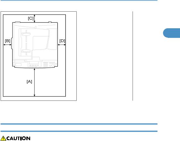
Minimum Space Requirements
Place the copier near the power source, providing clearance as shown:
14
Installation Requirements
1
A (front): 750 mm (30")
B (left): 150 mm (6")
C (rear): 50 mm (2")
D (right): 250 mm (10")
The recommended 750 mm front space is sufficient to allow the paper tray to be pulled out. Additional front space is required to allow operators to stand at the front of the machine.
Power Requirements
•Make sure that the wall outlet is near the machine and easily accessible. After. completing installation, make sure the plug fits firmly into the outlet.
•Avoid multi-wiring.
•Be sure to ground the machine
Input voltage:
North and South America, Taiwan: |
110 |
– 120 V, 60 Hz, 12 A |
|
|
|
Europe, Asia: |
220 |
– 240 V, 50/60 Hz, 7 A |
|
|
|
15
1. Installation
Copier Installation
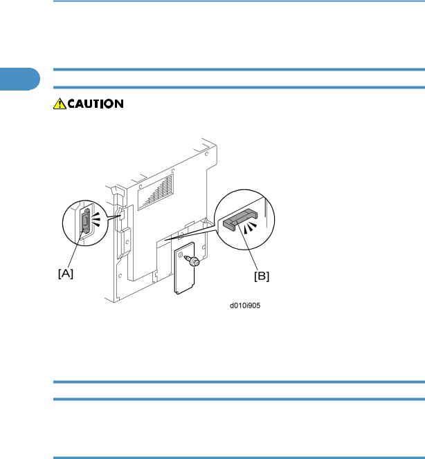
1 Power Sockets for Peripherals
• Make sure to plug the cables into the correct sockets.
[A]: Socket for ARDF (Rated voltage output max. DC24 V)
[B]: Socket for paper tray unit (Rated voltage output max. DC24 V)
Accessory Check
Check that you have the accessories in this list.
D010
No. |
Description |
Q’ty |
|
|
|
1 |
NECR-English (-17) |
1 |
|
|
|
2 |
EU Safety Sheet (-26, -27) |
1 |
|
|
|
3 |
Operating Instructions - Book (-17, -19, -21, -29) |
1 |
|
|
|
16

|
|
|
|
Copier Installation |
||
|
|
|
|
|
|
|
|
|
|
|
|
|
|
No. |
Description |
|
Q’ty |
|
|
|
|
|
|
|
|
|
|
4 |
Operating Instructions - CD-ROM (-17, -19, -21, -29) |
1 |
|
|
|
|
|
|
|
|
1 |
||
5 |
Language Kit (-26, -27) |
1 |
||||
|
|
|
|
|
|
|
6 |
Model Name Plate (-29) |
1 |
|
|
|
|
|
|
|
|
|
|
|
7 |
Emblem Cover (-29) |
1 |
|
|
|
|
|
|
|
|
|
|
|
D043 |
|
|
|
|
|
|
|
|
|
|
|
|
|
|
|
|
|
|
|
|
No. |
Description |
|
Q’ty |
|
|
|
|
|
|
|
|
|
|
1 |
Operating Instructions - Book |
|
1 |
|
|
|
|
|
|
|
|
|
|
2 |
Operating Instructions - CD-ROM |
|
1 |
|
|
|
|
|
|
|
|
|
|
3 |
Model Name Plate (-29) |
|
1 |
|
|
|
|
|
|
|
|
|
|
4 |
Emblem Cover (-29) |
|
1 |
|
|
|
|
|
|
|
|
|
|
5 |
Caution Sheet - CD-Driver (-29) |
|
1 |
|
|
|
|
|
|
|
|
|
|
6 |
Sheet -EULA |
|
1 |
|
|
|
|
|
|
|
|
|
|
Installation Procedure
• Unplug the machine power cord before starting the following procedure.
17

1. Installation
1
1. Remove filament tape and other padding.
2. Open the front door and remove the toner bottle holder [A].
18
Copier Installation
1
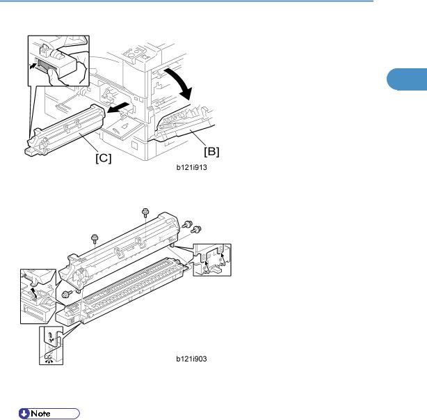
3. Open the right door [B], and remove the PCU (photo conductor unit) [C].
4.Separate the PCU into the upper part and the lower part ( x 5).
5.Put a sheet of paper on a level surface and place the upper part on it.
•This prevents foreign material from getting on the sleeve rollers
19
1. Installation
1
6.Distribute a pack of developer [D] to all openings equally.
•Do not spill the developer on the gears [E]. If you have spilled it, remove the developer by using a magnet or magnetized screwdriver.
•Do not turn the gear [E] too much. The developer may spill.
7.Reassemble the PCU and reinstall it.
8.Shake the toner bottle [F] several times. (Do not remove the bottle cap [G] before you shake the bottle.)
20
Copier Installation
9.Remove the bottle cap [G] and install the bottle on the holder. (Do not touch the inner cap [H].)
10.Set the holder (with the toner bottle) in the machine.
1
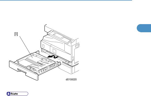
11.Pull out the paper tray [I] and adjust the positions of the end and side guides.
•To move the side guides, release the green lock on the rear side guide.
12.Install the optional ARDF or platen cover.
13.Plug in the main power cord and turn on the main switch.
14.Activate the SP mode and execute "Devlpr Initialize" (SP 3016-1).
15.Wait until the message "Completed" shows (about 45 seconds).
16.Activate the User Tools and select the menu "Language."
17.Specify a language. This language is used for the operation panel.
18.Load the paper in the paper tray and make a full size copy, and make sure the side-to-side and leading edge registrations are correct.
21

1. Installation
Platen Cover Installation
|
|
|
|
|
|
1 |
Accessory Check |
|
|
|
|
|
|
|
|
|
|
|
Check that you have the accessories indicated below. |
|
|
||
|
|
|
|
|
|
|
No. |
|
Description |
Q’ty |
|
|
|
|
|
|
|
|
1 |
|
Stepped Screw |
2 |
|
|
|
|
|
|
|
Installation Procedure
• Unplug the machine power cord before starting the following procedure.
Install the platen cover ( x 2).
22

ARDF Installation
ARDF Installation
|
|
Accessory Check |
1 |
|
|
Check the quantity and condition of the accessories against the following list.
No. |
Description |
Q’ty |
|
|
|
1 |
Scale Guide |
1 |
|
|
|
2 |
DF Exposure Glass |
1 |
|
|
|
3 |
Stud Screw |
2 |
|
|
|
4 |
Knob Screw |
2 |
|
|
|
5 |
Original Size Decal |
2 |
|
|
|
6 |
Screwdriver Tool |
1 |
|
|
|
7 |
Attention Decal – Top Cover |
1 |
|
|
|
8 |
Attention Decal – Scanner |
1 |
|
|
|
9 |
Cloth Holder |
1 |
|
|
|
10 |
Cloth |
1 |
|
|
|
11 |
Spacer*1 |
2 |
|
|
|
*1: These spacers are used for adjusting the trapezoid image.
23

1. Installation
Installation Procedure
1
• Unplug the copier power cord before starting the following procedure.
1. Remove the strips of tape.
2.Remove the left scale [A] ( x 2).
3.Peel off the backing [B] of the double-sided tape attached to the glass holder.
4.Place the DF exposure glass [C] on the glass holder.
24

ARDF Installation
•When installing the DF exposure glass, make sure that the painted mark [D] is placed to the downward, as shown.
5. |
Peel off the backing [E] of the double-sided tape attached to the rear side of the scale guide [F], then |
1 |
|
install it ( x 2 removed in step 2). |
|
6. |
Install the two stud screws [G]. |
|
7. |
Mount the DF on the copier, then slide the DF to the front as shown. |
|
8. |
Secure the DF unit with two screws [H]. |
|
9. |
Connect the cable [I] to the copier. |
|
10.Peel off the platen sheet [J] and place it on the exposure glass.
11.Line up the rear left corner of the platen sheet flush against corner [K] on the exposure glass.
12.Close the ARDF.
13.Attach the appropriate scale decal [L] as shown.
25
1. Installation
1
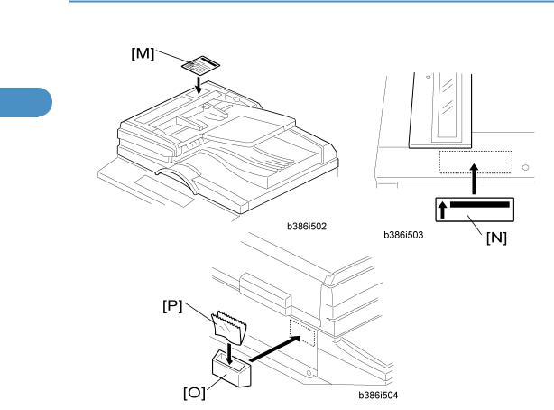
14.Attach the decal [M] to the top cover as shown, choosing the language most suitable for the machine installed.
15.Line up arrow on the decal [N] with the center of the ADF exposure glass as shown, and attach it to the cover. As with step 14, choose the language most suitable for the machine installed.
16.Attach the cloth holder [O] to the left side of the scanner as shown.
17.Insert the cloth [P] in the cloth holder.
18.Turn the main power switch on. Then check if the document feeder works properly.
19.Make a full size copy. Then check to make sure the registrations (side-to-side and leading edge) and image skew are correct. If they are not, adjust the registrations and image skew (refer to the service manual).
26
Two-tray Paper Tray Unit Installation
Two-tray Paper Tray Unit Installation
|
|
Accessory Check |
1 |
|
|
Check the quantity and condition of the accessories against the following list.
No. |
Description |
Q’ty |
|
|
|
1 |
Securing Bracket |
2 |
|
|
|
2 |
Screw - M4 x 8 |
4 |
|
|
|
Installation Procedure
•Unplug the machine power cord before starting the following procedure.
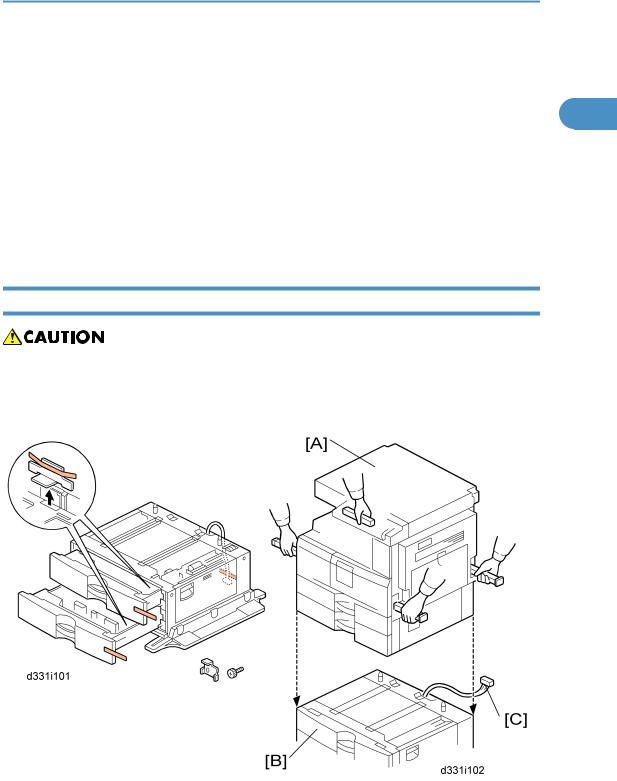
•The handles of the main machine for lifting must be inserted inside the machine and locked unless these handles are used for the installation or relocation of the main machine.
1. Remove the strips of tape.
27

1.Installation
2.Set the copier [A] on the paper tray unit [B].
•When installing the copier, be careful not to pinch the cable [C].
1
3.Remove the connector cover [D] (rivet screw x 1).
4.Connect the cable [E] to the copier, as shown.
5.Attach a securing bracket [F] to each side of the paper tray unit, as shown ( x 1 each).
6.Re-install the connector cover.
7.Remove the 2nd paper tray [G] and secure the paper tray unit with two screws [H].
8.Reinstall the 2nd paper tray.
9.Rotate the adjuster [I] until the machine cannot be pushed across the floor.
10.Loads paper into the paper trays and select the proper paper size.
11.Turn on the main switch.
12.Check the machine’s operation and copy quality.
28

One-Bin Tray Installation
One-Bin Tray Installation
|
|
Accessory Check |
1 |
|
|
Check the quantity and condition of the accessories.
No. |
|
Description |
Q’ty |
|
|
|
|
1 |
Installation procedure |
|
1 |
|
|
|
|
2 |
One-bin sorter |
|
1 |
|
|
|
|
3 |
Exit tray |
|
1 |
|
|
|
|
4 |
Tapping screw M3 x 6 |
|
1 |
|
|
|
|
Installation Procedure
• Unplug the machine power cord before starting the following procedure.
1.Remove the inverter tray [A].
2.Remove the rail [B] (2 knob screws).
3.Remove the sorter cap [C] (1 rivet).
29
Loading...