


20-496
PRO-2096 Digital Trunking
Mobile/Base Scanner
Please read this user’s guide before installing, setting up and using your new product
www.radioshack.com

Contents
Thank you for purchasing your Pro-2096 digital trunk scanner from RadioShack. You can mount your scanner in a fixed position and use it as a base scanner or you can use it as
a mobile scanner by mounting it in a vehicle. This scanner is the first of an innovative and exciting new generation, capable of receiving digital voice modulation from the newest and most sophisticated conventional and trunked radio networks. No additional hardware or add-on cards are needed.
user’s guide • quick start guide • preloaded data addendum
DC cable w/fuse
Scanner
Antenna |
AC adapter |
Mounting bracket
Knob (2)
Rubber washer (2)
Lock washer (2)
Screw (2)
DIN sleeve and keys (2)
Rubber foot (3)
2

The Basics
contents
your scanner’s keypad |
7 |
your scanner’s rear view |
9 |
your scanner’s display |
10 |
step 1: install your scanner |
11 |
mounting your scanner in your dashboard |
11 |
mobile mounting in your vehicle |
11 |
using your scanner as a base station |
12 |
step 2: power your scanner |
13 |
from a wall outlet |
13 |
through your vehicle’s ignition |
13 |
from your vehicle’s cigarrette lighter |
14 |
step 3: connect your scanner |
15 |
connect the supplied antenna |
15 |
connect an external antenna |
15 |
connect an external speaker or headphones |
16 |
step 4: set up your scanner |
17 |
squelch |
17 |
storing conventional frequencies |
17 |
deleting frequencies from channels |
18 |
searching and tuning |
19 |
basic scanning |
20 |
about channel-storage banks |
20 |
monitoring a single channel |
20 |
using CTCSS and DCS |
21 |
searching a preprogrammed frequency range |
21 |
search bank charts |
22 |
3

The Basics
searching for active frequencies |
27 |
using Zeromatic |
27 |
using seek search |
27 |
manually tuning to a frequency |
28 |
frequency copy |
29 |
copying a frequency into a specified channel |
29 |
copying a frequency to a vacant channel |
|
into a specified bank |
30 |
copying a frequency to the priority channel |
30 |
listening to the weather band |
31 |
same standby mode |
31 |
testing weather alert |
32 |
using delay |
33 |
locking out channels/frequencies |
33 |
locking out channels |
33 |
locking out frequencies |
34 |
reviewing locked-out search frequency |
34 |
clearing locked-out search frequencies |
35 |
clearing locked-out frequencies in search banks |
35 |
changing the receive mode |
35 |
using attenuator |
36 |
global attenuator |
37 |
turning the key tone on or off |
37 |
using the dimmer |
38 |
changing the display contrast |
38 |
virtual scanner |
39 |
using V-scanner |
40 |
using digital AGC |
45 |
cloning programmed data |
45 |
cloning v-scanner data |
46 |
full cloning |
47 |
selective cloning |
47 |
4

The Basics
trunking operation |
50 |
setting squelch for trunk scanning |
50 |
talkgroup ID hold |
50 |
turning an ID sub-bank on or off |
50 |
open and closed mode operation |
51 |
toggling open and closed modes |
52 |
manual ID lockout toggle |
52 |
activate ID lockout while scanning |
53 |
reviewing locked-out talkgroup IDs |
53 |
changing from ID text tag display |
|
to ID code display |
53 |
trunked delay function |
53 |
clearing talkgroups IDs |
54 |
clearing all talkgroup IDs in one bank |
55 |
programming trunked systems |
56 |
Motorola analog, digital, and APCO-25 systems |
56 |
EDACS systems |
57 |
Motorola VHF and UHF systems |
58 |
Motorola 800MHz splinter systems |
59 |
fleet maps |
59 |
programming the priority channel |
61 |
programming a stored channel frequency |
|
in the priority channel |
61 |
programming the priority channel directly |
61 |
programming a weather channel as the priority channel 62
turning priority on or off |
62 |
programming CTCSS/DCS channels |
63 |
storing talkgroup ids |
65 |
text tags |
67 |
assigning a text tag to a channel |
67 |
assigning a text tag to a group ID |
68 |
assigning a text tag to a channel-storage bank |
68 |
5

The Basics
text input chart |
69 |
using channel receive modes |
69 |
updating the DSP firmware |
69 |
truobleshooting |
70 |
resetting/initializing your scanner |
71 |
resetting your scanner |
71 |
initializing your scanner |
72 |
care |
73 |
replacing the fuse |
73 |
service and repair |
73 |
specifications |
74 |
The FCC wants you to know |
77 |
scanning legally |
77 |
glossary |
78 |
warranty |
84 |
©2004 RadioShack Corporation.
All Rights Reserved.
RadioShack, RadioShack.com. Hypersearch, Hyperscan, V-Scanner, and Adaptaplug are trademarks used by RadioShack Corporation.
Motorola, Smartnet, ASTRO and Privacy Plus are registered trademarks of Motorla Inc.
EDACS is a registered trademark of MA-COM Inc.
The IMBE(TM) Voice Coding Technology embodied in this product is protected by intellectual property rights including patent rights, copyrights and trade secrets of Digital Voice Systems, Inc. This voice coding Technology is licensed solely for use witthin this Communications Equipment. The user of this Technology is explicitly prohibited from attempting to decompile, reverse engineer, or disassemble the Object Code, or in any other way convert the Object Code into a human readable form.
U.S. Pat. Nos. 5,870,405 and 5,517,511.
This device made under license under one or more of the following U.S. Patents: 4,590,473; 4,636,791; 5,148,482; 5,185,796; 5,271,017; 5,377,229
6

The Basics
your scanner’s keypad
TRUNK — stores the trunking ID code or holds the trunking ID while scanning.
L/OUT — locks out selected channels and ID codes, and skips specified frequencies during a search.
CLEAR — clears an incorrect entry.
PROG — programs frequencies in selected channels.
PWR/VOL/SQ — long knob turns OFF/ON, and controls volume. Short knob controls squelch.
PC/IF — connect data cable for cloning or connecting to a PC.
s — attach headphones with 1/8” jack here.
7

The Basics
FUNC — press in combination with other keys to
perform various functions.
ATT — Press to activate attenuation (reduce scanner sensitivity, block strong signals). Press again to deactivate attenuation.
DIM — adjusts the backlight level (Light, Dark, or OFF).
TUNE — Press TUNE, PAUSE then e or d to tune to a
frequency.
PAUSE — pauses search or tune operation.
e or d — press to scan or search in either direction.
WX — press to scan programmed weather channels.
See p. 31
TEXT — press to input text.
SRCH — press to search through search banks.
MAN — press to manually enter a channel number.
PRI — turns the priority function on or off.
MODE — press to change the receive mode.
SCAN — press to scan programmed channels.
8

The Basics
Press to enter a number or a character (in text mode).
./DELAY — press to enter a decimal point, space, or
hyphen. Press to program delay time for a channel/search bank.
ENT — press to confirm frequency and text entries.
your scanner’s rear view
ANT — connect the supplied antenna or an external antenna here.
SCREW HOLE — use to mount the scanner in a car with some hardware (screw not supplied).
RESET— press to reset your scanner.
DC 13.8V — connect a power source here.
EXT SP — connect an
external speaker here.
9
The Basics
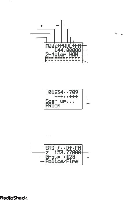
your scanner’s display
Priority On/Off Indicator
Receiving a Signal ( no signal) |
Attenuator On/Off Indicator |
||||
Delay On/Off Indecator |
|||||
Channel 00-(49) |
|||||
Lockout On/Off Indecator |
|||||
Bank 0-(9) |
|||||
(While Scanning, Scanning Direction, |
|
or |
.) |
||
(M)anual Mode |
Open/Closed Mode Indecator |
||||
(P)rogram |
|||||
|
|
|
|
||
(S)can |
Receiving Mode |
||||
|
|||||
|
Receiving Frequency |
||||
|
Stored Text |
||||
|
or Bank and Channel Numbe r |
||||
|
Detected ID Display |
||||
|
(Trunking & CTCSS/DCS) |
||||

 Bank Off


 Open Mode
Closed Mode
Scan Mode
Search Range Number
Zeromatic On/Off Indicator |
|
|
Frequency |
Sub-Group |
Bank Off |
Search Range Name |
|
Search Mode
10
The Basics
step 1: install your scanner
You can mount your digital trunking scanner in your vehicle, install it for mobility, or install it as a base station.
mounting your scanner in your dashboard
Note
Note
If you are unsure about how to install your scanner in your vehicle, consult your automobile manufacturer, dealer, or a qualified installer. Before installing, confirm your scanner fits in the desired mounting area and you have all the necessary materials. Your scanner requires a 2 x 71/8 x 5 5/16 inch
(50 x 180 x 135 mm) mounting area.
1.Remove the four rear screws and pull off the black case before installing your scanner.
2.Install the DIN sleeve into the opening in your dashboard, lip facing out.
3.Push out the top and bottom tabs to hold the sleeve firmly in place.
4. Slide the scanner into the |
|
sleeve until it locks in place. |
|
To remove your scanner from the DIN sleeve, insert the two  keys straight into the scanner’s front panel. Then, remove the scanner by pulling front panel.
When mounting in your dashboard, you will need to
 connect an external antenna and an external speaker.
mobile mounting in your vehicle
You can mount your scanner under the dashboard, or on top of it, using the mounting bracket.
11

The Basics
1. |
Attach the three |
|
|
protective rubber |
|
|
feet to the mounting |
|
|
bracket when you |
|
|
use the scanner on a |
|
|
flat surface. Do not |
|
|
use them when you |
|
|
mount the bracket with |
|
|
screws. |
|
2. |
Use the supplied |
|
|
mounting bracket as |
|
|
a template to mark |
|
|
positions for the two |
|
|
mounting screws. |
3.At the marked positions,
drill holes slightly smaller than the screws.
4.Remove the paper backing from each washer and stick one inside of each bracket’s ear, aligning the washer’s hole with the bracket’s hole.
5.Attach the mounting bracket to your vehicle’s surface using the supplied screws and lockwashers.
6.Slide the scanner into the bracket, aligning the scanner’s holes with the holes in the bracket, and then screw the mounting knobs into the scanner.
When drilling holes, be sure to avoid obstructions behind
Note
the mounting surface. Consult a qualified installer if in doubt.
using your scanner as a base station
You can place your scanner on a desk, shelf, or table to use it as a base station. Since the speaker is on the bottom of the scanner, you may want to use the mounting bracket to elevate your scanner off the surface for better sound. Follow the mobile vehicle mounting instructions above to affix your scanner to a desk, shelf, table or other flat surface (except that the bracket will be below the scanner).
12

The Basics
step 2: power your scanner
You can power your scanner from a wall outlet, through your vehicle’s ignition, or from your vehicle’s cigarette lighter.
from a wall outlet
1.Connect the tip of the supplied AC adapter to the DC 13.8V jack at the rear of your scanner.
2.Plug the AC adapter into your wall outlet.
Note
You must use a Class 2 power source that supplies 13.8V DC and delivers at least 600mA. Its center tip must be set to positive and its plug must fit the scanner’s DC 13.8V jack. Using an adapter that does not meet these specifications could damage the scanner or the adapter.
Warning! |
To prevent electric shock, do not use the AC adapter’s |
polarized plug with an extension cord, receptacle, or other outlet unless you can fully insert the blades to prevent blade exposure.
through your vehicle’s ignition
1.Disconnect the cable from the negative (-) terminal of your vehicle’s battery.
2.Ground the black wire of the supplied DC power cord to your vehicle’s chassis.
13

The Basics
Note |
Be sure the grounding screw makes complete contact |
|
with the metal frame of your vehicle. |
3.Connect the red wire of the supplied DC power cord to a voltage source that turns on and off with the ignition switch, such as a spare accessory terminal in your vehicle’s fuse box.
4.Insert the power cord’s barrel
plug into the scanner’s
DC 13.8V jack.
5. Reconnect the cable to the |
Rear View |
negative (-) terminal of your |
|
vehicle’s battery. |
|
Note
You must use a power source that supplies 12V DC and delivers at least 600 mA. Its center tip must be set to positive and its plug must fit the scanner’s DC 13.8V jack. The supplied DC power cord meets these specifications. Using a power cord that does not meet these specifications could damage the scanner or the adapter.
from your vehicle’s cigarrette lighter
To power your scanner from a 12V power source in your vehicle, such as a cigarette-lighter socket, you need a 12V, 600 mA DC cigarette-lighter adapter (not supplied), available at your local RadioShack store.
1.Insert the adapter’s barrel plug into the scanner’s DC 13.8V jack.
2.Plug the adapter’s other end into your vehicle’s cigarette lighter or power socket.
Note |
When you use a cigarette-lighter adapter, you might hear |
|
electrical noise from your engine while scanning. This is |
|
normal. |
14

The Basics
step 3: connect your scanner
connect the supplied antenna
Push the antenna onto your scanner’s antenna connector and rotate until it locks into place.
Your scanner’s sensitivity to various frequencies depends on
its location and the antenna’s
length. For best reception, adjust the antenna’s length as follows:
Frequency |
Antenna Length |
|
|
25-54 MHz |
Extend fully |
|
|
108-174 MHz |
Extend 4 segments |
|
|
216-225 MHz |
Extend 3 segments |
|
|
406-1300 MHz |
Collapse fully |
|
|
connect an external antenna
You will need to connect an external antenna when you mount your scanner in the dashboard of your vehicle. You may also want to connect an external antenna if you use your scanner as a base station.
Your local RadioShack store sells a variety of antennas. Always use 50-ohm coaxial
cable, such as RG-58 or RG-8, to connect an outdoor antenna. For
lengths exceeding 50 feet, use RG-8 low-loss dielectric coaxial
cable. If your coaxial cable does not have a BNC connector, you will also need a BNC adapter (not supplied).
15

The Basics
Warning! Use extreme caution when installing or removing an
outdoor antenna. If the antenna starts to fall, let it go! It could contact overhead power lines. If the antenna
touches a power line, touching the antenna, mast, cable, or guy wires can cause electrocution and death. Call the power company to remove the antenna. Do not attempt to do so yourself.
connect an external speaker or headphones
When you mount your scanner in your dashboard, you will need to connect an external speaker or headphones.
Connect |
Connect external |
headphones here |
speaker here |
listening safely
To protect your hearing, follow these guidelines when you use headphones.
•Adjust VOL (volume) to its lowest level before putting on headphones. With the headphones on, adjust VOL to a comfortable level.
•Avoid increasing the volume once you set it. Over time, your sensitivity to volume decreases, so volume levels that do not cause discomfort might damage your hearing.
•Avoid listening at high volume levels. Prolonged exposure to high volume levels can cause permanent hearing loss.
traffic safety
Do not wear headphones while driving. This can create a traffic hazard and is illegal in some areas. Even though some headphones let you hear outside sounds when you listen at normal levels, they still can present a traffic hazard.
16

The Basics
step 4: set up your scanner
squelch
1.Rotate VOL clockwise to turn on your scanner. DSP LOADING and Welcome To Digital Trunking appears. In a few seconds, you might hear a hissing sound.
2.Adjust VOL to a comfortable listening level.
3.Rotate SQ (squelch) fully counterclockwise to OFF. Then, rotate SQ clockwise until the hissing sound stops.
4.To turn off the scanner, turn VOL counterclockwise to OFF.
storing conventional frequencies
1.Turn on your scanner and press PROG.
2.Select the desired channel storage bank and channel, and then press PROG.
3.Use the number keys and ./DELAY (to enter the decimal point) to enter the frequency you want to store.
4.Press ENT to store the frequency.
5.The scanner configures the channels you enter after a two second delay. A D appears at the top of the display. If you do not want the scanner to pause before it resumes scanning, press ./DELAY until D no longer appears on the display.
6.To receive conventional frequencies, including AM, FM/Digital, CTCSS and DCS, press MODE. For more information on CTCSS and DCS programming, see “Programming CTCSS/DCS channels”.
7.If desired, program a text tag for the channel. See “Assigning a Text Tag to a Channel”.
8.To program additional channels, press PROG or e or d to move to the next channel memory location.
17

The Basics
Notes |
If you make a mistake entering the frequency, Invalid Freq |
|
briefly appears. |
|
When you store a frequency by pressing ENT, your |
|
scanner beeps. |
|
Press CLEAR to backspace and correct a character, or hold |
|
down CLEAR for about two seconds to clear the entire field |
|
and start over. |
|
Your scanner automatically rounds the frequency you |
|
enter to the nearest valid frequency. For example, if you |
|
enter 151.53, your scanner accepts it as 151.5275. Reception |
|
of the frequency will not be adversely affected. |
|
If you enter a frequency that is already stored, an error |
|
tone sounds. Dupl.f and the duplicated frequency number |
|
appear. Press CLEAR and enter another frequency. |
|
You can replace any stored frequency by selecting the |
|
desired bank and channel, pressing PROG, and then |
|
entering the new frequency. |
|
Press FUNC, and then CLEAR to erase programmed |
|
frequency data. |
deleting frequencies from channels
In certain circumstances you may wish to completely clear the contents of a channel. One example would be to create empty channels in a selected channel storage bank so the frequency copy function has empty channels available for copied frequencies. See “Copying a Frequency to a Vacant Channel into a Specified Bank”.
1.Press PROG.
2.Use the number keys or e or d to select the frequency you want to delete.
3.Press FUNC, and then CLEAR. The frequency is cleared, and 0.00000 appears on the display.
18

The Basics
searching and tuning
You can search for transmissions using the scanner’s preprogrammed search banks. The search banks include six preprogrammed search ranges, SR0 to SR5. You can change the search range of Bank SR6 manually by setting the lower and higher ends of the search range.
Notes |
You can use the scanner’s delay feature while searching. |
|
See “Using Delay”. |
|
You can set CTCSS or DCS mode when searching any |
|
range, except for SR0, SR1, and SR4. The scanner will |
|
display detected CTCSS or DCS codes depending on the |
|
mode setting. See “Using CTCSS and DCS”. |
|
The scanner does not search locked-out frequencies |
|
while searching ranges. |
|
You can use PAUSE to temporarily pause searching. The |
|
scanner will remain on the frequency that was active |
|
when PAUSE was pressed until you press PAUSE again. |
|
You can simply listen to the radio traffic on the paused |
|
frequency, or copy the frequency to a channel before |
|
resuming your search. |
19

The Basics
basic scanning
Press SCAN to begin scanning channels. The scanner scans through all channels in the active channel storage bank. See “About Channel Storage Banks”.
•You must store frequencies into channels before you can scan them. The scanner does not scan through empty channels.
•To change the scanning direction, press e or d while scanning.
about channel-storage banks
•To turn on a channel storage bank, press the number key corresponding to the desired bank until the bank’s number appears on the display.
•To turn off a channel storage bank, press the number key corresponding to the desired bank until the bank’s number disappears from the display.
•The scanner does not scan channels within a bank you have turned off; however, you can manually select any channel in a storage bank, even if the bank is turned off.
•You cannot turn off all channel storage banks. There must always be at least one active channel storage bank.
monitoring a single channel
You can monitor a single channel by manually navigating to that channel. The scanner will receive transmissions only on that frequency.
20
Beyond the Basics
using CTCSS and DCS
Your scanner’s advanced, DSP-based CTCSS and DCS, decoder allows you to listen only to a frequency group that is of interest to you. Simply specify the group’s specific CTCSS or DCS code for a certain frequency. CTCSS and DCS can also help reduce interfering signals that cause your scanner to stop on one channel.
When your scanner stops on a conventional frequency that is configured for CTCSS or DCS, it checks for a match between the transmitted CTCSS or DCS code and the code stored in channel memory. If the transmitted and stored codes match, the scanner stops on the transmission and allows the audio to pass to the speaker. If the codes do not match, the scanner resumes scanning. If the special “search” code is in use,
the scanner instantly displays any detected CTCSS code if programmed for CTCSS mode, or DCS code if programmed for DCS code. You can store the detected code into channel memory by pressing ENT while the code is displayed.
searching a preprogrammed frequency range
The scanner contains these preprogrammed search ranges, stored in the search bank (SR0-SR6).
Bank |
Band |
SR0 |
Marine |
SR1 |
CB |
SR2 |
FRS/GMRS/MURS |
SR3 |
Police/Fire |
SR4 |
Aircraft |
SR5 |
Ham |
SR6 |
Limit search (User configurable) |
1. Repeatedly press SRCH to select a search bank.
21

Beyond the Basics
2.In the marine, CB and FRS bands, you can directly select a channel or search through the band. When M appears on the left on the second line, you can directly select a channel (see “Search Bank Charts”). Use the numeric keypad to select a specific two-digit channel number (for example, press 1 6 to select Channel 16, or 0 5 to select
channel 5). You can also change the channels by pressing e or d.
There are several group banks in the SR3 Police/Fire and SR5 ham bands. You can turn on the groups by pressing the group numbers. For example, to turn on group 0, press 0.
3.Press FUNC, SRCH while M appears in SR0, SR1 or SR2. M changes to S. Then search through the band. To return to the previous mode, press FUNC, SRCH.
4.Rotate SQ clockwise and leave it set to a point just after the hissing sound stops. After two seconds (if the delay feature is on), the received frequency appears and the scanner starts searching.
5.When the scanner finds an active frequency, it stops searching, and resumes when the transmission ends. If delay is programmed with the search range the scanner will pause for a reply before search resumes.
search bank charts
Search bank: SR0 Marine band
Note |
For some Marine frequencies, two frequencies are |
assigned to one channel, for example, 157.000 and 161.600 are assigned to Channel 20.
22

Beyond the Basics
Receive mode: FM/Digital
Ch. |
Frequency |
Ch. |
Frequency |
|
(MHz) |
|
(MHz) |
01 |
156.0500 |
05 |
156.2500 |
06 |
156.3000 |
07 |
156.3500 |
08 |
156.4000 |
09 |
156.4500 |
10 |
156.5000 |
11 |
156.5500 |
12 |
156.6000 |
13 |
156.6500 |
14 |
156.7000 |
15 |
156.7500 |
16 |
156.8000 |
17 |
156.8500 |
18 |
156.9000 |
19 |
156.9500 |
20 |
157.0000 |
21 |
157.0500 |
|
161.6000 |
|
|
22 |
157.1000 |
23 |
157.1500 |
24 |
157.2000 |
25 |
157.2500 |
|
161.8000 |
|
161.8500 |
26 |
157.3000 |
27 |
157.3500 |
|
161.9000 |
|
161.9500 |
28 |
157.4000 |
63 |
157.1750 |
|
162.0000 |
|
|
64 |
156.2250 |
65 |
156.2750 |
|
160.8250 |
|
|
66 |
156.3250 |
67 |
156.3750 |
68 |
156.4250 |
69 |
156.4750 |
70 |
156.5250 |
71 |
156.5750 |
72 |
156.6250 |
73 |
156.6750 |
74 |
156.7250 |
77 |
156.8750 |
78 |
156.9250 |
79 |
156.9750 |
80 |
157.0250 |
81 |
157.0750 |
82 |
157.1250 |
83 |
157.1750 |
84 |
157.2250 |
85 |
157.2750 |
|
161.8250 |
|
161.8750 |
|
|
|
|
23

Beyond the Basics
86 |
157.3250 |
87 |
157.3750 |
|
161.9250 |
|
161.9750 |
88 |
157.4250 |
|
|
Search bank: SR1 CB band
Receive mode: AM
Ch. |
Frequency |
Ch. |
Frequency |
|
(MHz) |
|
(MHz) |
01 |
26.9650 |
02 |
26.9750 |
03 |
26.9850 |
04 |
27.0050 |
05 |
27.0150 |
06 |
27.0250 |
07 |
27.0350 |
08 |
27.0550 |
09 |
27.0650 |
10 |
27.0750 |
11 |
27.0850 |
12 |
27.1050 |
13 |
27.1150 |
14 |
27.1250 |
15 |
27.1350 |
16 |
27.1550 |
17 |
27.1650 |
18 |
27.1750 |
19 |
27.1850 |
20 |
27.2050 |
21 |
27.2150 |
22 |
27.2250 |
23 |
27.2550 |
24 |
27.2350 |
25 |
27.2450 |
26 |
27.2650 |
27 |
27.2750 |
28 |
27.2850 |
29 |
27.2950 |
30 |
27.3050 |
31 |
27.3150 |
32 |
27.3250 |
33 |
27.3350 |
34 |
27.3450 |
35 |
27.3550 |
36 |
27.3650 |
37 |
27.3750 |
38 |
27.3850 |
39 |
27.3950 |
40 |
27.4050 |
Search bank: SR2 FRS/GMRS/MURS
Receive Mode: FM/Digital, CT or DC
24

Beyond the Basics
Ch. |
Frequency |
Ch. |
Frequency |
|
(MHz) |
|
(MHz) |
01 |
462.5625 |
02 |
462.5875 |
03 |
462.6125 |
04 |
462.6375 |
05 |
462.6625 |
06 |
462.6875 |
07 |
462.7125 |
08 |
467.5625 |
09 |
467.5875 |
10 |
467.6125 |
11 |
467.6375 |
12 |
467.6625 |
13 |
467.6875 |
14 |
467.7125 |
15 |
462.5500 |
16 |
462.5750 |
17 |
462.6000 |
18 |
462.6250 |
19 |
462.6500 |
20 |
462.6750 |
21 |
462.7000 |
22 |
462.7250 |
23 |
151.8200 |
24 |
151.8800 |
25 |
151.9400 |
26 |
154.5700 |
27 |
154.6000 |
|
|
Search bank: SR3 Police/Fire band
Receive Mode: FM/Digital, CT or DC
Group |
Frequency (MHz) |
Step (kHz) |
0 |
33.420 – 33.980 |
20 |
|
37.020 – 37.420 |
20 |
|
39.020 – 39.980 |
20 |
|
42.020 – 42.940 |
20 |
|
44.620 – 45.860 |
40 |
|
45.880 |
|
|
45.900 |
|
|
45.940 – 46.060 |
40 |
|
46.080 – 46.500 |
20 |
25

Beyond the Basics
1 |
153.770 – 154.130 |
60 |
|
154.145 – 154.445 |
15 |
|
154.650 – 154.950 |
15 |
|
155.010 – 155.370 |
60 |
|
155.415 – 155.700 |
15 |
|
155.730 – 156.210 |
60 |
|
158.730 – 159.210 |
60 |
|
166.250 |
|
|
170.150 |
|
2 |
453.0375 – 453.9625 |
12.5 |
|
458.0375 – 458.9625 |
12.5 |
|
460.0125 – 460.6375 |
12.5 |
|
465.0125 – 465.6375 |
12.5 |
3 |
851.0125 – 860.9875 |
25 |
|
866.0125 – 868.9875 |
12.5 |
Search bank: SR4 Aircraft
Receive mode: AM
Frequency (MHz) |
Step (kHz) |
108.000 – 136.9875 |
12.5 |
Search bank: SR5 Ham band
Receive mode: FM/Digital, CT, DC, AM (depends on group)
Group |
Frequency (MHz) |
Step (kHz) |
0 |
28.0000 – 29.7000 |
5 |
1 |
50.0000 – 54.0000 |
5 |
2 |
144.0000 – 148.0000 |
5 |
3 |
222.0000 – 225.0000 |
5 |
4 |
420.0000 – 450.0000 |
12.5 |
5 |
1240.0000 – |
6.25 |
|
1300.0000 |
|
26
 Loading...