


49-830.fm Page 1 Thursday, August 19, 1999 10:37 AM
Cat. No. 49-830
OWNER’S MANUAL
RS-3000 Auto Security Alarm System
Please read this entire manual before you begin installation.

49-830.fm Page 2 Thursday, August 19, 1999 10:37 AM
FEATURES
Your RS-3000 Auto Security Alarm System’s voice alert warns away potential thieves and alerts you to trouble in a clear, loud, male voice and shouts out a panic alert in a female voice. It also includes advanced features that help protect your vehicle from theft, yet you can install it in less than an hour. The two convenient key-chain transmitters lets you arm and disarm the system, sound a panic alert, or activate the car finder feature when you are away from your vehicle.
Your RS-3000 includes these features.
Note: The following features marked with an asterisk (*) might qualify you for a discount on your vehicle insurance premium. Show your insurance agent the supplied certificate.
Talking Alarm with 120 dB Alert — advises you of the alarm’s status (armed or disarmed) and warns away potential thieves.
Piercing, 120 dB Siren — loud enough to be heard from hundreds of feet away.
Passive Arming — automatically arms the system after you exit the vehicle.
Starter Kill — prevents anyone from starting your vehicle when the system is armed.
Electronic Dual-Stage Shock Sensor — sounds a pre-alert warning the first time someone strikes your vehicle, then sounds the alert if it is hit again within 30 seconds.
Current Sensing System — triggers the alert when a door or trunk is opened and the vehicle’s dome or trunk light turns on, or when your vehicle is hot wired, by sensing the current draw.
Current Sensor Bypass — lets you turn off current sensing if other electronic devices in your vehicle (such as a high-power audio system or cellular phone) make your alarm sound false alerts.
Status Indicator — mounted in plain view, lets you easily determine the status of the alarm system (armed or disarmed) and warns away potential thieves.
High Theft Alert Mode — lets you set the alarm to announce that it is armed or to chirp every 30 seconds.
Two Easy-to-Use Key-Chain Remotes — let you easily control your alarm from a distance.
Car Finder — lets you make the alarm sound beeps to help you find your vehicle in a crowded parking lot.
2

49-830.fm Page 3 Thursday, August 19, 1999 10:37 AM
Instant Panic Alarm — calls out in a female voice to alert others nearby that you need assistance when you are in or near your vehicle.
Valet Mode — lets you easily prevent passive arming when the vehicle is being serviced, valet parked, or washed.
Programmable Options — lets you customize several of your alarm’s options.
Accessory Trigger Output — provides a negative trigger to activate (but not power) accessory sensors.
Violation Confirmation — beeps three times or says “I was tampered with!” when you disarm the system after the alarm has sounded, to let you know what happened while you were away from the vehicle.
Computer-Controlled Fan Sensor
— can tell the difference between your vehicle’s dome or trunk light and an electric cooling fan (which can make other alarms sound a false alert) without using additional wiring.
Toll-Free Help — if you have any questions about or problems with your alarm system, just call:
1-800-598-2527
Your system requires one 9-volt alkaline battery to maintain operation if the main power lead is disconnected.
Warning: Your alarm system’s alerts are painfully loud. Take care during installation to keep your head away from the system once you connect power.
FCC INFORMATION
Your alarm system might cause TV or radio interference even when it is operating properly. To determine whether your system is causing the interference, move your vehicle out of the area. If the interference goes away, your alarm system was causing the interference. Try to eliminate the interference by:
•Keeping your system away from the receiver
•Contacting your local RadioShack store for help
If you cannot eliminate the interference, the FCC requires that you stop using your alarm system.
Need Help? Call 1-800-598-2527 |
3 |

49-830.fm Page 4 Thursday, August 19, 1999 10:37 AM
CONTENTS |
|
Installing the System ..................................................................................... |
5 |
Supplied Items ........................................................................................... |
5 |
Installation Order ....................................................................................... |
6 |
Connecting the Starter Disable Module ..................................................... |
6 |
Connecting the System to Power .............................................................. |
7 |
Activating the Remote Controls ................................................................. |
8 |
Installing the Backup Battery ..................................................................... |
8 |
Mounting the System ................................................................................. |
9 |
Installing the Status Indicator .................................................................. |
10 |
Using the Alarm System ............................................................................... |
11 |
Arming the Alarm ...................................................................................... |
11 |
Temporarily Reducing the Shock Sensor’s Sensitivity ....................... |
11 |
High Theft Alert .................................................................................. |
11 |
Sounding the Panic Alarm ........................................................................ |
11 |
Alarm Violations ....................................................................................... |
12 |
Disarming the System ............................................................................. |
12 |
Using the Car Finder ............................................................................... |
12 |
Setting the System’s Options .................................................................. |
13 |
Setting the Shock Sensor’s Sensitivity .............................................. |
13 |
Setting the Current Sensor ............................................................... |
13 |
Setting the Valet Mode (Passive Arming/Disarming) ........................ |
14 |
Troubleshooting ........................................................................................... |
15 |
Care and Maintenance ................................................................................. |
17 |
Replacing the Fuse .................................................................................. |
18 |
Replacing a Remote Control’s Battery .................................................... |
18 |
Specifications ............................................................................................... |
19 |
4 |
Need Help? Call 1-800-598-2527 |
49-830.fm Page 5 Thursday, August 19, 1999 10:37 AM
INSTALLING THE SYSTEM
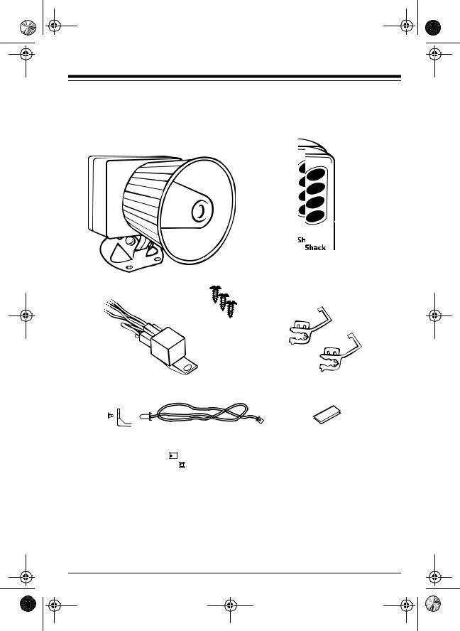
SUPPLIED ITEMS
Your alarm system includes the following items:
Two Four-Button Remotes
Main System
Mounting Screws
Starter Disable Relay |
Wire Tap-In Connectors |
Status Indicator with Bracket and Harness |
Double-Sided Tape |
||
|
|
|
|
|
|
|
|
Wire Ties
Need Help? Call 1-800-598-2527 |
5 |

49-830.fm Page 6 Thursday, August 19, 1999 10:37 AM
INSTALLATION ORDER
You can install your system in just 6 easy steps:
1.Connect the starter disable module.
2.Connect the system to power.
3.Train the remote controls.
4.Install the backup battery.
5.Mount the system.
6.Install the status indicator.
We recommend you get a wiring diagram for your vehicle before you begin, so you can easily find your vehicle’s starter solenoid wire. Wiring diagrams are available from your vehicle’s dealer or from the Auto Security Helpline at 1-800-598-2527.
You also need a 12-volt test lamp or DC voltmeter and a wire-piercing probe adapter (such as RadioShack Cat. No. 278-715) to ensure proper installation.
CONNECTING THE STARTER DISABLE MODULE
The starter disable module interrupts power to your vehicle’s starter solenoid so the vehicle does not start when the system is armed. Follow these steps to connect the module.
1.Using the starter solenoid’s colorcoded wires as a guide, locate the wire that goes from your vehicle’s ignition (key) switch to the solenoid. This wire is most easily found where the wires connect to the ignition switch near the steering column.
2.Connect the negative (usually black) lead from a 12-volt test lamp or DC voltmeter to a metal vehicle body part.
3.Connect the wire-piercing probe to the positive lead and press the pin tip through the solenoid wire’s insulation and into the wire itself.
4.Start your vehicle. The test light should light or the meter should indicate voltage only while the engine is cranking (not while it is stopped or running).
If the test fails, repeat Steps 2–4 using a different wire until you find the correct one.
6 |
Need Help? Call 1-800-598-2527 |
 Loading...