


®
Industrial
918
938
INSTRUCTION MANUAL
This instruction manual applies to machines from the following serial numbers onwards:
# 2 682 700 
296-12-18 600/002 Betriebsanleitung engl. 06.09

This Instruction Manual is valid for all models and subclasses listed in the chapter "Specifications ".
The reprinting, copying or translation of PFAFF Instruction Manuals, whether in whole or in part, is only permitted with our previous authorization and with written reference to the source.
PFAFF Industriesysteme und Maschinen AG
Hans-Geiger-Str. 12 - IG Nord
D-67661 Kaiserslautern

Contents
|
Contents ................................................................................. |
Chapter – Page |
|||
1 |
Safety ........................................................................................................................... |
|
1 |
- |
1 |
1.01 |
Regulations ................................................................................................................... |
|
1 |
- |
1 |
1.02 |
General notes on safety ................................................................................................ |
|
1 |
- |
1 |
1.03 |
Safety symbols ............................................................................................................. |
|
1 |
- |
2 |
1.04 |
Important notes for the user ......................................................................................... |
|
1 |
- |
2 |
1.05 |
Notes for operating and technical staff ......................................................................... |
|
1 |
- |
3 |
1.05.01 |
Operating staff .............................................................................................................. |
|
1 |
- |
3 |
1.05.02 |
Technical staff ............................................................................................................... |
|
1 |
- |
3 |
1.06 |
Danger .......................................................................................................................... |
|
1 |
- |
4 |
2 |
Proper use.................................................................................................................... |
|
2 |
- |
1 |
3 |
Specifications .............................................................................................................. |
|
3 |
- |
1 |
4 |
Disposal of Machine ................................................................................................... |
|
4 |
- |
1 |
5 |
Transportation, packing and storage ......................................................................... |
|
5 |
- |
1 |
5.01 |
Transportation to customer's premises ........................................................................ |
|
5 |
- |
1 |
5.02 |
Transportation inside the customer's premises ............................................................ |
|
5 |
- |
1 |
5.03 |
Disposal of packing materials ........................................................................................ |
|
5 |
- |
1 |
5.04 |
Storage ......................................................................................................................... |
|
5 |
- |
1 |
6 |
Explanation of symbols .............................................................................................. |
|
6 |
- |
1 |
7 |
Controls ....................................................................................................................... |
|
7 |
- |
1 |
7.01 |
Main switch .................................................................................................................. |
|
7 |
- |
1 |
7.02 |
Keys on the machine head (only on machines with Quick-flange motor) ...................... |
|
7 |
- |
1 |
7.03 |
Pedal ............................................................................................................................. |
|
7 |
- |
2 |
7.04 |
Lever for raising presser foot ........................................................................................ |
|
7 |
- |
2 |
7.05 |
Adjustment lever for zigzag stitch and needle position ................................................. |
|
7 |
- |
3 |
7.06 |
Reverse-feed key .......................................................................................................... |
|
7 |
- |
3 |
7.07 |
Stitch length adjustment wheel .................................................................................... |
|
7 |
- |
4 |
7.08 |
Adjustment lever of the underedge trimmer -771/.. ...................................................... 7 - |
4 |
|||
7.09 |
Control panel (only on machines with Quick-flange motor) ........................................... |
|
7 |
- |
5 |
7.09.01 |
Screen displays ............................................................................................................. |
|
7 |
- |
5 |
7.09.02 |
Function keys ................................................................................................................ |
|
7 |
- |
5 |
8 |
Installation and commissioning ................................................................................. |
|
8 - |
1 |
|
8.01 |
Installation ..................................................................................................................... |
|
8 |
- |
1 |
8.01.01 |
Adjusting the table height ............................................................................................. |
|
8 |
- |
1 |
8.01.02 |
Mounting the upper V-belt guard / Fitting the machine cover ........................................ |
|
8 |
- |
2 |
8.01.03 |
Fitting the reel stand ..................................................................................................... |
|
8 |
- |
2 |
8.02 |
Fitting the Quick-flange motor....................................................................................... |
|
8 |
- |
3 |
8.03 |
Fit the belt guard of the Quick flange-motor. ................................................................ |
|
8 |
- |
3 |
8.04 |
Connect the plug-type connections and earth cable of the Quick-flange motor. ........... |
8 |
- |
4 |
|
|
|
|
|
|
|

Contents
|
Contents ................................................................................. |
Chapter – Page |
|||
8.05 |
Commissioning ............................................................................................................. |
|
8 |
- |
5 |
8.06 |
Switching the machine on/off ....................................................................................... |
|
8 |
- |
5 |
8.07 |
Basic setting of the machine drive unit (only on machines with Quick-flange motor) |
... 8 |
- |
6 |
|
8.08 |
Mounting/connecting the start inhibitor (only on machines with Quick-flange motor) ... |
8 |
- |
8 |
|
9 |
Setting up .................................................................................................................... |
|
9 |
- |
1 |
9.01 |
Inserting the needle ...................................................................................................... |
|
9 |
- |
1 |
9.02 |
Winding the bobbin thread; adjusting the primary thread tension ................................. |
|
9 |
- |
2 |
9.03 |
Removing/inserting the bobbin case ............................................................................. |
|
9 |
- |
3 |
9.04 |
Threading the bobbin case, adjusting the thread tension .............................................. |
|
9 |
- |
3 |
9.04.01 |
PFAFF 938 without thread trimmer ............................................................................... |
|
9 |
- |
3 |
9.04.02 |
PFAFF 938 with thread trimmer .................................................................................... |
|
9 |
- |
4 |
9.04.03 |
PFAFF 918 .................................................................................................................... |
|
9 |
- |
4 |
9.05 |
Threading the needle thread / Adjusting the needle thread tension .............................. |
|
9 |
- |
5 |
9.06 |
Setting the zigzag stitch and the stitch position ............................................................ |
|
9 |
- |
6 |
9.07 |
Adjusting the stitch length ............................................................................................ |
|
9 |
- |
6 |
9.08 |
Entering the start and end backtacks ............................................................................ |
|
9 |
- |
7 |
10 |
Sewing ....................................................................................................................... |
|
10 |
- |
1 |
10.01 |
Darning program ......................................................................................................... |
|
10 |
- |
2 |
10.02 |
Counted seam ............................................................................................................. |
|
10 |
- |
2 |
10.03 |
Error messages ........................................................................................................... |
|
10 |
- |
3 |
11 |
Care and maintenance .............................................................................................. |
|
11 |
- |
1 |
11.01 |
Cleaning ...................................................................................................................... |
|
11 |
- |
1 |
11.02 |
Lubricating the hook .................................................................................................... |
|
11 |
- |
2 |
11.03 |
Oiling the zigzag drive ................................................................................................. |
|
11 |
- |
3 |
11.04 |
Cleaning the air filter of the air-filter / lubricator ........................................................... |
|
11 |
- |
4 |
11.05 |
Checking/adjusting the air pressure ............................................................................ |
|
11 |
- |
4 |
12 |
Adjustment ................................................................................................................ |
|
12 |
- |
1 |
12.01 |
Notes on adjustment ................................................................................................... |
|
12 |
- |
1 |
12.02 |
Tools, gauges and other accessories for adjusting ...................................................... |
|
12 |
- |
1 |
12.03 |
Abbreviations .............................................................................................................. |
|
12 |
- |
1 |
12.04 |
Check and adjustment aid ........................................................................................... |
|
12 |
- |
2 |
12.05 |
Adjusting the basic machine ....................................................................................... |
|
12 |
- |
3 |
12.05.01 |
Balancing weight ......................................................................................................... |
|
12 |
- |
3 |
12.05.02 |
Centering the needle in the needle hole (in sewing direction) ..................................... |
|
12 |
- |
4 |
12.05.03 |
Parallel guiding of the needle bar ................................................................................ |
|
12 |
- |
5 |
12.05.04 |
Locking lever ............................................................................................................... |
|
12 |
- |
6 |
12.05.05 |
Zero stitch and zigzag stitch scale ............................................................................... |
|
12 |
- |
7 |
12.05.06 |
Centering the needle in the needle hole (crosswise to sewing direction).................... |
|
12 |
- |
8 |
12.05.07 |
Zigzag stitch width ...................................................................................................... |
|
12 |
- |
9 |
12.05.08 |
Zigzag stitch movement .............................................................................................. |
|
12 |
- 10 |
|
12.05.09 |
Needle penetration symmetry (left, centre and right) .................................................. |
|
12 |
- 11 |
|
|
|
|
|
|
|

Contents
|
Contents ................................................................................. |
Chapter – Page |
||
12.05.10 |
Needle position adjustment lever ................................................................................ |
12 |
- 12 |
|
12.05.11 |
Zero position of the bottom feed dog (with closed gear box) ...................................... |
12 |
- 13 |
|
12.05.12 |
Zeroing the bottom feed (with open gearbox) ............................................................. |
12 |
- 14 |
|
12.05.13 |
Feeding motion of the bottom feed dog ..................................................................... |
12 |
- 15 |
|
12.05.14 |
Lifting motion of the bottom feed dog ........................................................................ |
12 |
- 16 |
|
12.05.15 |
Drive belt in the gearbox housing ................................................................................ |
12 |
- 17 |
|
12.05.16 |
Hook bearing bracket .................................................................................................. |
12 |
- 18 |
|
12.05.17 |
Hook lubrication .......................................................................................................... |
12 |
- 19 |
|
12.05.18 |
Pre-adjusting the needle height ................................................................................... |
12 |
- 20 |
|
12.05.19 |
Needle rise, hook-to-needle clearance and bobbin case positioning-finger .................. |
12 |
- 21 |
|
12.05.20 |
Final adjustment of the needle height ......................................................................... |
12 |
- 22 |
|
12.05.21 |
Bobbin case opener position ....................................................................................... |
12 |
- 23 |
|
12.05.22 |
Bobbin case opener motion ........................................................................................ |
12 |
- 24 |
|
12.05.23 |
Bottom feed dog height .............................................................................................. |
12 |
- 25 |
|
12.05.24 |
Presser foot to needle plate clearance ........................................................................ |
12 |
- 26 |
|
12.05.25 |
Needle thread tension release (on machines without -900/24).................................... |
12 |
- 27 |
|
12.05.26 |
Presser foot pressure ................................................................................................. |
12 |
- 28 |
|
12.05.27 |
Thread diverter pin ...................................................................................................... |
12 |
- 29 |
|
12.05.28 |
Limiting the knee lever stroke ..................................................................................... |
12 |
- 30 |
|
12.05.29 |
Knee lever play ............................................................................................................ |
12 |
- 31 |
|
12.05.30 |
Bobbin winder ............................................................................................................. |
12 |
- 32 |
|
12.06 |
Adjusting the underedge trimmer -771/04 ................................................................... |
12 |
- 33 |
|
12.06.01 |
Resting position of the knife ....................................................................................... |
12 |
- 33 |
|
12.06.02 |
Knife height ................................................................................................................. |
12 |
- 34 |
|
12.06.03 |
Positioning of the knife ............................................................................................... |
12 |
- 35 |
|
12.06.04 |
Knife drive switch ....................................................................................................... |
12 |
- 36 |
|
12.06.05 |
Workpiece guard ......................................................................................................... |
12 |
- 37 |
|
12.07 |
Adjusting the thread trimmer -900/24 ......................................................................... |
12 |
- 38 |
|
12.07.01 |
Axial position of the control cam ................................................................................. |
12 |
- 38 |
|
12.07.02 |
Preliminary adjustment of the control cam ................................................................. |
12 |
- 39 |
|
12.07.03 |
Position of the thread catcher and cutting test ........................................................... |
12 |
- 40 |
|
12.07.04 |
Readjustment of the control cam ................................................................................ |
12 |
- 41 |
|
12.07.05 |
Needle thread tension release .................................................................................... |
12 |
- 42 |
|
12.08 |
Parameter settings ...................................................................................................... |
12 |
- 43 |
|
12.08.01 |
Selecting the user level ............................................................................................... |
12 |
- 43 |
|
12.08.02 |
Example of a parameter input ..................................................................................... |
12 |
- 44 |
|
12.08.03 |
List of parameters ....................................................................................................... |
12 |
- 45 |
|
12.09 |
Reset / Cold start ........................................................................................................ |
12 |
- 46 |
|
12.10 |
Explanation of the error signals ................................................................................... |
12 |
- 47 |
|
12.11 |
Internet update of the machine software .................................................................... |
12 |
- 48 |
|
13 |
Wearing parts ............................................................................................................ |
13 - |
1 |
|
14 |
Circuit diagrams ........................................................................................................ |
14 |
- |
1 |
|
|
|
|
|

Safety
1 Safety
1.01 Regulations
This machine is constructed in accordance with the European regulations indicated in the conformity and manufacturer's declarations.
In addition to this instruction manual, please also observe all generally accepted, statutory and other legal requirements, including those of the user's country, and the applicable pollution control regulations!
The valid regulations of the regional social insurance society for occupational accidents or other supervisory authorities are to be strictly adhered to!
1.02 General notes on safety
●The machine must only be operated by adequately trained operators and only when the instruction manual has been fully read and understood!
●All notices on safety and the instruction manual of the motor manufacturer are to be read before the machine is put into operation!
●All notes on the machine concerning danger and safety must be observed!
●The machine must be used for the purpose for which it is intended and must not be operated without its safety devices; all regulations relevant to safety must be adhered to.
●When part sets are changed (e.g. needle, presser foot, needle plate, feed dog or bob-bin), during threading, when the workplace is left unattended and during maintenance work, the machine must be isolated from the power supply by turning off the on/off switch or removing the plug from the mains!
●Daily maintenance work must only be carried out by appropriately trained persons!
●Repairs and special maintenance work must only be carried out by qualified technical staff or persons with appropriate training!
●During maintenance or repairs on the pneumatic system the machine must be isolated from the compressed air supply! The only exception to this is when adjustments or function checks are carried out by appropriately trained technical staff!
●Work on the electrical equipment must only be carried out by technical staff who are qualified to do so!
●Work on parts or equipment connected to the power supply is not permitted! The only exceptions to this are specified in regulations EN 50110.
●Conversion or modification of the machine must only be carried out under observation of all relevant safety regulations!
1 - 1
Safety
●Only spare parts which have been approved by us are to be used for repairs! We draw special attention to the fact that spare parts and accessories not supplied by us have not been subjected to testing nor approval by us. Fitting and/or use of any such parts may cause negative changes to the design characteristics of the machine. We shall not accept any liability for damage caused by the use of non-original parts.
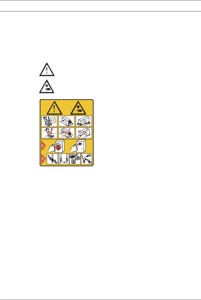
1.03 Safety symbols
Danger!
Special points to observe.
Danger of injury to operating or technical staff!
Caution
Do not operate without finger guard and safety devices.
Before threading, changing bobbin and needle, cleaning etc. switch off main switch.
 I
I
1.04 Important notes for the user
●This instruction manual belongs to the equipment of the machine and must be available to the operating staff at all times.
This instruction manual must be read before the machine is operated for the first time.
●Both operating and technical staff must be instructed on the safety devices of the machine and on safe working methods.
●It is the duty of the user to operate the machine in perfect running order only.
●The user must ensure that none of the safety devices are removed nor put out of working order.
●The user must ensure that only authorized persons operate and work on the machine. For further information please refer to your PFAFF agency.
1 - 2

Safety
1.05 Notesforoperatingandtechnicalstaff
1.05.01 Operating staff
Operating staff are the persons responsible for setting up, operating and cleaning the machine and for eliminating any malfunctioning in the sewing area.
The operating staff is obliged to observe the following points:
●The notes on safety in this instruction manual must always be observed!
●Any working methods, which adversely affect the safety of the machine, must be avoided.!
●Loose-fitting clothing should be avoided. No jewellery, such as chains and rings, should be worn!
●Ensure that only authorised persons enter the danger area of the machine!
●Any changes occurring on the machine, which may affect its safety, must be reported to the user immediately.
1.05.02 Technical staff
Technical staff are persons who have been trained in electrical engineering/electronics and mechanical engineering. They are responsible for lubricating, servicing, repairing and adjusting the machine.
The technical staff is obliged to observe the following points:
●The notes on safety in this instruction manual must always be observed!
●Before carrying out any adjustment or repair work the main switch must be switched off and measures taken to prevent it from being switched on again!
●Never work on parts or equipment still connected to the power supply! Exceptions are only permissible in accordance with the regulations EN 50110.
●All safety covers must be replaced after the completion of maintenance or repair work!
1 - 3
Safety
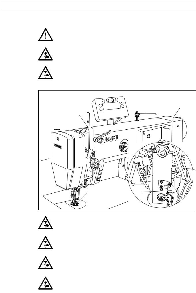
1.06 Danger
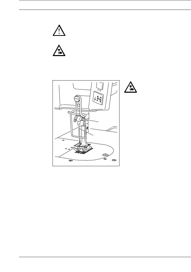
A working area of1meter is to be kept free both in front of and behind the machine while it is in operation so that it is always easily accessible.
Never reach into the sewing area while sewing! Danger of injury by the needle!
Never leave objects on the table while adjusting the machine settings!
Objects can become trapped or be slung away! Danger of injury!
|
4 |
1 |
|
|
92-002 |
2 |
3 |
Fig. 1 - 01 |
|
Do not operate the machine without the take-up lever guard1!
Danger of injury through the movement of the take-up lever.
Do not operate the machine without finger guard2!
Danger of injury from the needle!
Do not operate machines with Quick-flange motor without start inhibitor3!
Danger of injury if the machine is started accidentally!
When using an external motor do not operate the machine without belt guard4!
Danger of injury from the drive belts!
1 - 4

Proper use
2 Proper use
The PFAFF918U is a high-speed zigzag sewing machine with bottom feed and large hook. The PFAFF938U is a high-speed zigzag sewing machine with bottom feed.
The machines are used for producing zigzag lockstitch seams in the clothing and linen industry.
Any use of these machines which is not approved by the manufacturer shall be considered as improper use! The manufacturer shall not be liable for any damage arising out of improper use! Proper use shall also be considered to include compliance with the operation, adjustment, service and repair measures specified by the manufacturer!
2 - 1
|
|
Specifications |
|
3 |
Specifications ▲ |
|
|
|
Stitch type: ........................................................................................ |
304 (zigzag lockstitch) |
|
|
Needle system: ............................................................................................................. |
|
438 |
|
Needle size in 1/100 mm: |
|
|
|
Model A: ................................................................................................................... |
|
60 - 70 |
|
Model B: ................................................................................................................. |
|
80 - 100 |
|
Effective balance wheel diameter: ........................................................................... |
|
65 mm |
|
Presser foot clearance: .............................................................................................. |
|
7 mm |
|
Clearance width: .................................................................................................... |
|
260 mm |
|
Clearance height: ................................................................................................... |
|
130 mm |
|
Bedplate dimensions: ................................................................................... |
|
476 x 177 mm |
|
Sewing head dimensions: |
|
|
|
Length: .............................................................................................................. |
|
ca. 550 mm |
|
Width: ............................................................................................................... |
|
ca. 180 mm |
|
Height (above table): ......................................................................................... |
|
ca. 300 mm |
|
Max. stitch length |
|
|
|
PFAFF 918-6/01: ...................................................................................................... |
|
4,5 mm |
|
PFAFF 938-6/01; -6/27: ............................................................................................ |
|
2,5 mm |
|
Max. speed |
|
|
|
PFAFF 918: ................................................................................................... |
|
5000 Sti/min |
|
PFAFF 938-6/01; -771/04-6/27: ...................................................................... |
|
5500 Sti/min |
|
PFAFF 938-34/01 R: ...................................................................................... |
|
6000 Sti/min |
|
Max. stitch with |
|
|
|
PFAFF 918: ........................................................................................................... |
|
10,0 mm |
|
PFAFF 938-6/01: ...................................................................................................... |
|
6,0 mm |
|
PFAFF 938-771/04-6/27: .......................................................................................... |
|
3,0 mm |
|
PFAFF 938-34/01 R: ................................................................................................ |
|
4,5 mm |
|
Connection data: |
|
|
|
Operating voltage: ........................................................................... |
230 V ± 10%, 50/60 Hz |
|
|
Max. power ............................................................................................................. |
|
1,2 kVA |
|
Fuse protection: ............................................................................................ |
|
1 x 16 A, inert |
|
Noise data: |
|
|
|
Noise emission level at workplace with a sewing speed of 4000 spm: ..... |
L < 80 dB(A) |
|
|
|
|
pA |
|
(Noise measurement in accordance with DIN 45 635-48-A-1, ISO 11204, ISO 3744, ISO 4871) |
||
|
Net weight of sewing head: .................................................................................. |
|
ca. 46 kg |
|
Gross weight of sewing head: .............................................................................. |
|
ca. 54 kg |
▲ Subject to alterations
Depending on the stitch length, the maximum speed is reduced automatically within the max. pre-set value.
■ Kpa = 2.5 dB
3 - 1

Disposal of Machine
4DisposalofMachine
●Proper disposal of the machine is the responsibility of the customer.
●The materials used for the machine are steel, aluminium, brass and various plastic materials.
The electrical equipment comprises plastic materials and copper.
●The machine is to be disposed of according to the locally valid pollution control regulations; if necessary, a specialist ist to be commissioned.
Care must be taken that parts soiled with lubricants are disposed of separately
according to the locally valid pollution control regulations!
4 - 1

|
Transportation, packing and storage |
5 |
Transportation,packingandstorage |
5.01 |
Transportationtocustomer'spremises |
|
The machines are delivered completely packed. |
5.02 |
Transportationinsidethecustomer'spremises |
|
The manufacturer cannot be made liable for transportation inside the customer's premises |
|
nor to other operating locations. It must be ensured that the machines are only transported |
|
in an upright position. |
5.03 |
Disposalofpackingmaterials |
|
The packing materials of this machine comprise paper, cardboard and VCE fibre. Proper dis- |
|
posal of the packing material is the responsibility of the customer. |
5.04 |
Storage |
|
If the machine is not in use, it can be stored as it is for a period of up to six months, but It |
should be protected against dust and moisture.
If the machine is stored for longer periods, the individual parts, especially the surfaces of moving parts, must be protected against corrosion, e.g. by a film of oil.
5 - 1
Explanation of symbols
6 Explanationofsymbols
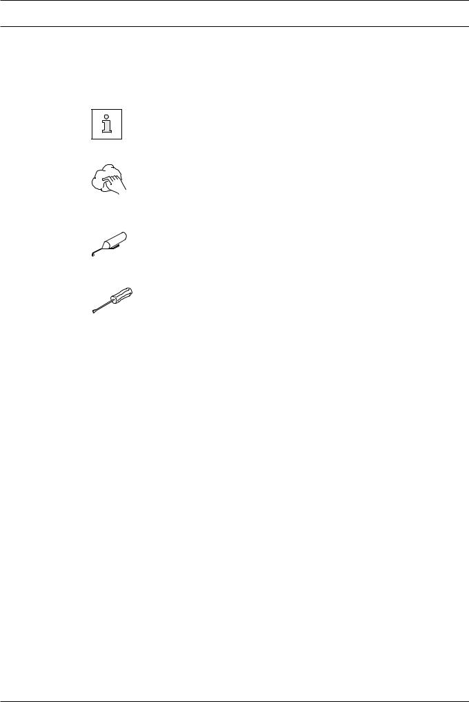
In this instruction manual, work to be carried out or important information is accentuated by symbols. These symbols have the following meanings:
Note, information
Cleaning, care
Lubrication
Maintenance, repairs, adjustment, service work (only to be carried out by technical staff)
6 - 1
Controls
7 Controls
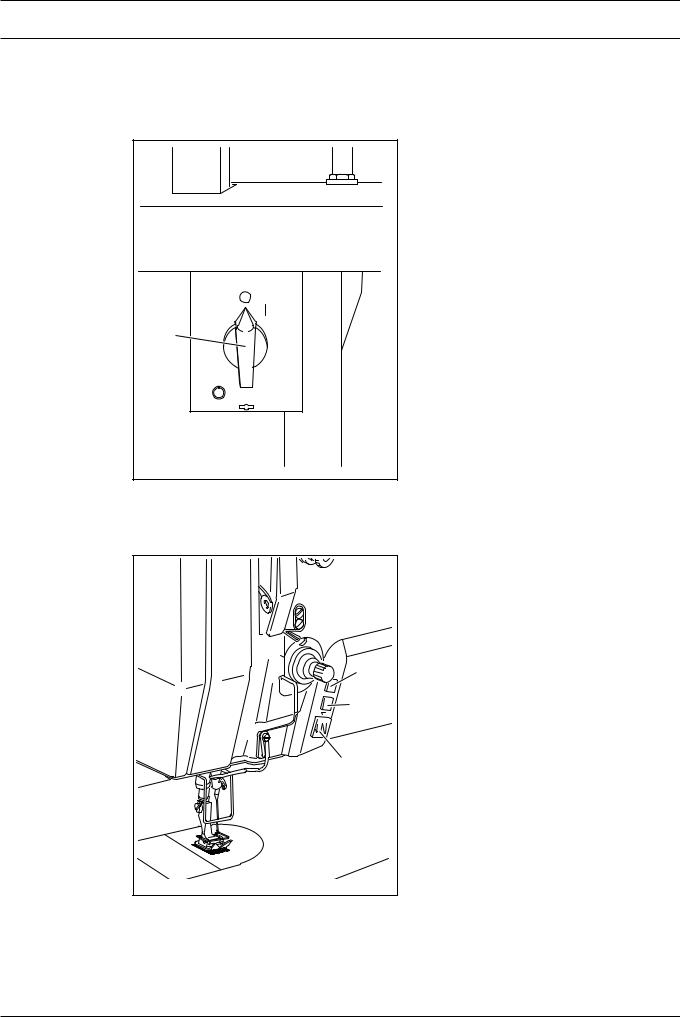
7.01 Mainswitch
1 |
|
Fig. 7 - 01 |
77-005 |
|
●The machine is switched on or off by turning the main switch1.
7.02 |
Keysonthemachinehead (only on machines with Quick-flange motor) |
3 |
2 |
1 |
4 |
Fig. 7 - 02 |
●As long as key1 is pressed during sewing, the machine sews in reverse.
●Keys2 and3 can be allocated with corresponding parameter settings, see theMotorInstructionManual.
7 - 1
Controls
7.03 |
Pedal |
|
|
0 |
= |
|
1 |
= |
|
2 |
= |
|
3 |
= |
|
0 |
|
|
1 |
|
|
2 |
|
|
3 |
|
|
Fig. 7 - 03 |
|
Neutral position
Sewing
Raise presser foot
Trim thread
7.04 Lever for raising presser foot
1 |
Fig. 7 - 04 |
●The presser foot is raised by turning lever1.
7 - 2

Controls
7.05 Adjustmentleverforzigzagstitchandneedleposition
|
|
|
● The zigzag stitch adjustment lever1 is |
||
|
|
4 |
used for adjusting the width of the zigzag |
||
|
|
|
stitch. |
|
|
|
|
|
● To change the position of the adjustment |
||
|
L |
M |
lever, the locking lever2 must be |
||
|
pressed against the adjustment lever1. |
||||
|
R |
||||
|
|
||||
3 |
|
|
|
|
|
|
|
|
|
|
|
|
|
|
|
|
The current zigzag-stitch width |
|
|
|
|
|
can be seen on scale3. |
|
|
1 |
● By turning the needle-position |
||
|
|
|
adjustment lever4 the required needle |
||
|
|
|
position can be set. |
||
|
|
2 |
L |
= |
needle-position left |
|
|
|
|||
|
|
|
M = |
needle-position center |
|
|
|
|
R = |
needle-position right |
|
Fig. 7 - 05 |
|
|
|
|
|
7.06 |
Reverse-feed key |
1 |
Fig. 7 - 06 |
●The machine sews in reverse as long as the reverse-feed key1 is pressed.
7 - 3
Controls
7.07 |
Stitchlengthadjustmentwheel |
|
● The stitch length can be adjusted by |
|
turning the stitch length adjustment |
|
wheel1. |
|
The stitch length setting can be |
|
read on scale2. |
|
1 |
|
2 |
|
08 |
|
Fig. 7 - 07 |
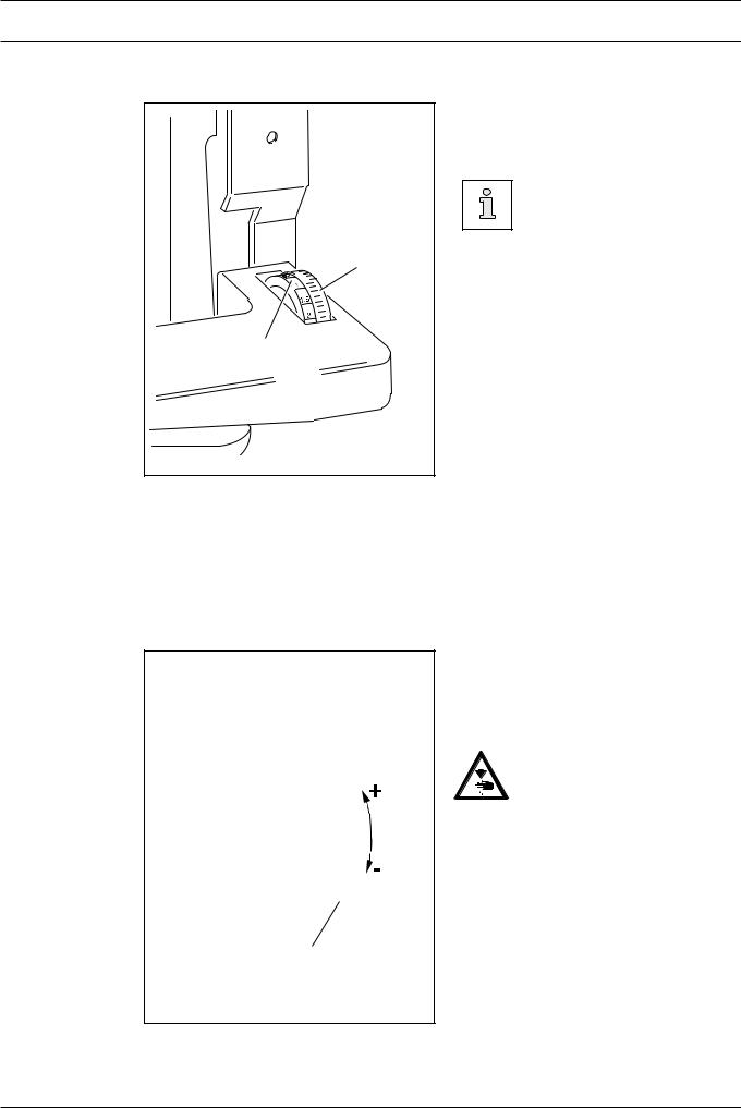
7.08 Adjustment lever of the underedge trimmer -771/04
● By pulling and turning lever1 towards "+", the underedge trimmer is switched on and the knife stroke set.
Do not touch the knife while it is running!
Danger of injury from the moving knife.
1
Fig. 7 - 08
7 - 4
Controls
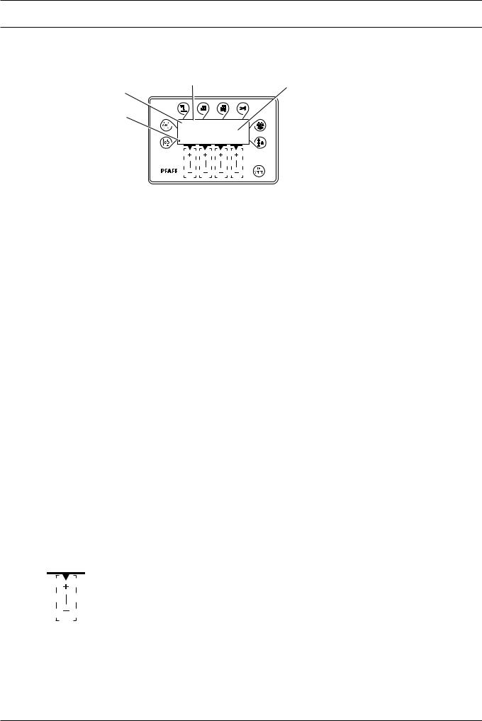
7.09 |
Controlpanel (only on machines with Quick-flange motor) |
|||
|
2 |
|
|
4 |
|
1 |
|
|
|
|
|
|
|
|
|
3 |
|
|
|
|
SPEED |
|
TE |
ERROR |
|
3 |
3 |
3 |
3 |
|
A |
B |
C |
D |
The control panel consists of display1 and the function keys described below. The display1 consists of a single-line alpha-numerical, 7 segment LCD display with 8 symbols. The texts
2, located above and next to the LCD display, show the respective status of the function keys and the operating status of the machine. The control panels switches on all LCDsegments and the horn automatically for a short time during the power-on phase, after which the lettering PFAFF appears on the display, until the higher-ranking control unit sends commands to the control panel.
The function keys are located around the display1. They are foil-packed without permanent marking and without contact signal. Fixed functions are allocated to the keys, seeChapter 7.09.02Functionkeys.
7.09.01 Screen displays
●Activated functions are displayed with a triangular marking3 below or next to the respective function key.
●In the sewing mode all relevant sewing data is displayed and can be changed directly, depending on the status of the machine, see alsoChapter10Sewing.
●During the parameter input the selected parameter number with the corresponding value is displayed, seeChapter12.08.02Exampleofaparameterinput.
7.09.02 Function keys
The function keys described below are used basically to switch machine functions on and off.
Each time a key is pressed, this must be confirmed by at least one beep tone. Irrespective of the machine mode a double beep signal is given if invalid keys are pressed or maximum values reached.
If a corresponding value has to be set for the activated function, this is carried out with the corresponding+/-key. By pressing and holding the corresponding+/-key, the relevant numerical value4 is changed slowly to begin with. If the corresponding+/-key is held down longer, the values change more quickly.
7 - 5

Controls
Startbacktacks
●If this key is pressed, the backtacks at the beginning of the seam (start backtacks) are switched on or off. The number of forward stitches (A) or reverse stitches (B) for the start backtacks can be changed by pressing the +/-key underneath. To convert from double backtack to single backtack set the number of stitches for the corresponding seam section at zero.
End backtacks
●If this key is pressed, the backtacks at the end of the seam (end backtacks) are switched on or off. The number of reverse stitches (C) or forward stitches (D) can be changed by pressing the+/-key underneath. To convert from double backtack to single backtack set the number of stitches for the corresponding seam section at zero.
Needleposition
●If this key is pressed the "needle raised after sewing stop" function is switched on or off. When the function is switched on, the needle positions at t.d.c. after sewing stops.
Footpositionafterstop
●If this key is pressed the "foot raised after sewing stop" function is switched on or off. When the function is switched on, the presser foot is raised after sewing stops.
Footpositionaftertrimming
●If this key is pressed the "foot raised after thread trimming" function is switched on or off. When the function is switched on, the presser foot is raised after thread trimming.
Threadtrimmer
● If this key is pressed the thread trimming function is switched on or off.
Darningprogram
●If this key is pressed the darning program function is switched on or off. The counted seam function is switched off automatically.
Countedseam
●If this key is pressed the counted seam function is switched on or off. The darning program function is switched off automatically.
TE/Speed
●If this key is pressed once the speed limit for the sewing mode is activated.
●If this key is pressed twice (within 5 seconds) the machine changes from sewing to input mode.
7 - 6
Installation and commissioning
8 Installationandcommissioning
The machine must only be installed and commissioned by qualified personnel!
All relevant safety regulations must be strictly adhered to!
If the machine is delivered without a table, be sure to use a stand and table top that can hold the weight of the machine with its motor.
It is very important to ensure that the stand of the machine is firm and steady, also during sewing.
8.01 Installation
The site where the machine is installed must be provided with suitable connections for electric current.
It must be ensured that the standing surface of the machine site is firm and horizontal, and that sufficient lighting is provided for.
For packing and transportation reasons the table top is in the lowered position.
The table height is adjusted as described below.
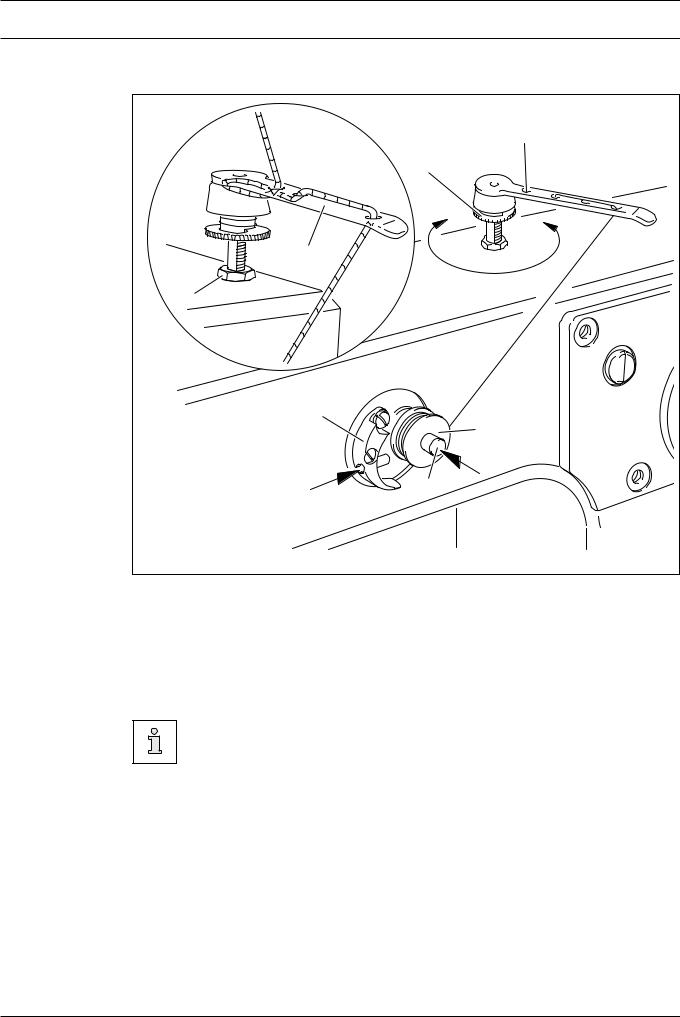
8.01.01 Adjusting the table height
2 |
1 |
1
92-010
Fig. 8 - 01
●Loosen screws1 and2 and set the table height as required.
●Firmly tighten screw1.
●Set the required pedal position and tighten screw2.
8 - 1
Installation and commissioning
8.01.02 Mounting the upper V-belt guard / Fitting the machine cover
|
|
|
● Slide the left and right halves of the V- |
|
|
|
belt guard into place with the slots |
|
|
|
behind the heads of screws1 and2. |
|
|
|
● Screw screw3 with distance bush4 into |
|
|
|
threaded hole5. |
|
1 |
|
● Align the V-belt guard, taking care that |
|
|
clip6 is behind slot7 and in front of |
|
|
|
|
|
|
|
8 |
distance bush4. |
9 |
2 |
|
● Tighten screws1 and2 (through holes 8 |
|
|
|
and9) and screw3. |
|
5 |
6 |
● When using an external motor, the motor |
|
|
cover must also be fitted as described by |
|
|
|
|
|
|
7 |
|
the motor manufacturer. |
|
|
81-007 |
|
|
|
|
|
|
4 |
|
|
Fig. 8 - 02 |
3 |
|
|
|
|
|
8.01.03 Fitting the reel stand
Fig. 8 - 03 |
●Fit the reel stand as shown inFig.8-03.
●Afterwards insert the stand in the hole in the table top and secure it with the nuts provided.
8 - 2

Installation and commissioning
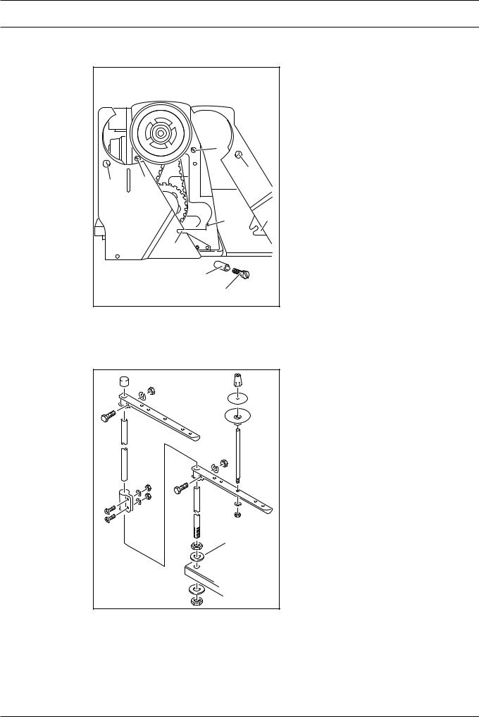
8.02 |
Fitting the Quick-flange motor. |
|
5 |
|
8 |
|
|
7 |
|
|
3 |
6 |
|
2 |
||
|
||
4 |
1 |
|
Fig. 8 - 04 |
|
●Loosen screws1 and remove toothed belt wheel2 from the motor shaft3.
●Attach bearing plate4 to the motor5 with screws6 as shown inFig.8-04.
●Slide toothed belt wheel2 onto the motor shaft 3 and fasten with screws1.
●Slightly tilt bearing plate4 with motor5 to the side and place the toothed belt7 on the toothed belt wheels.
●Align bearing plate4 of motor5 on the machine case and attach it with screws8.
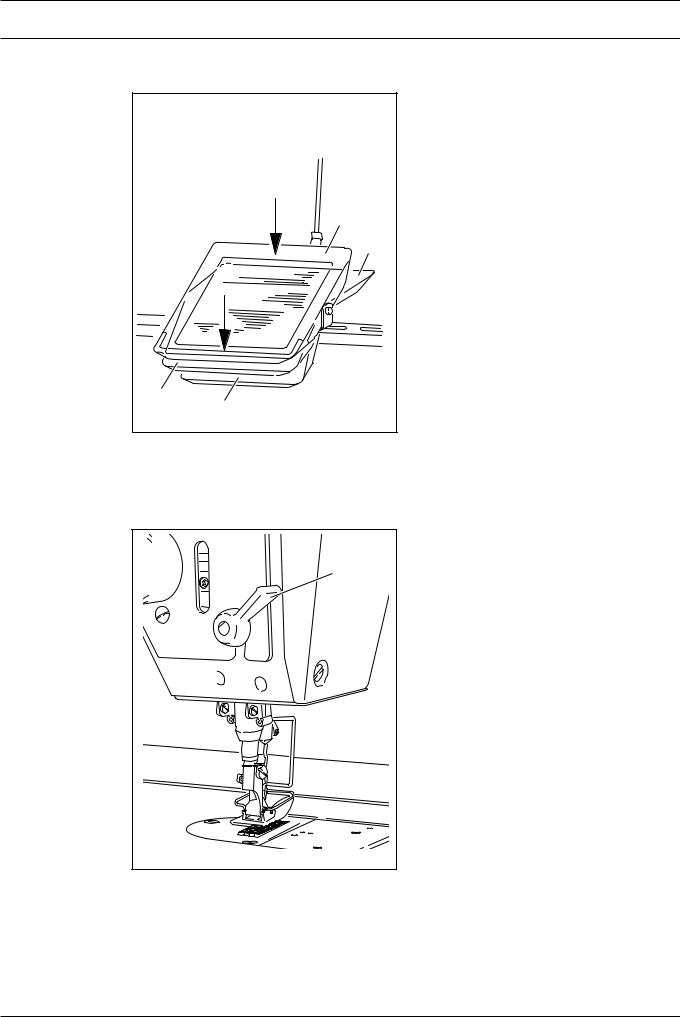
8.03 FitthebeltguardoftheQuickflange-motor.
3 |
● Attach belt guard1 with screws2 and3. |
|
|
1 |
|
2 |
|
Fig. 8 - 05 |
92-050 |
|
8 - 3
Installation and commissioning
8.04 Connecttheplug-typeconnectionsandearthcableoftheQuick-flangemotor.
7 |
6 |
A |
8 |
B |
1 |
2 |
7 |
3 |
5 |
4 |
Fig. 8 - 06 |
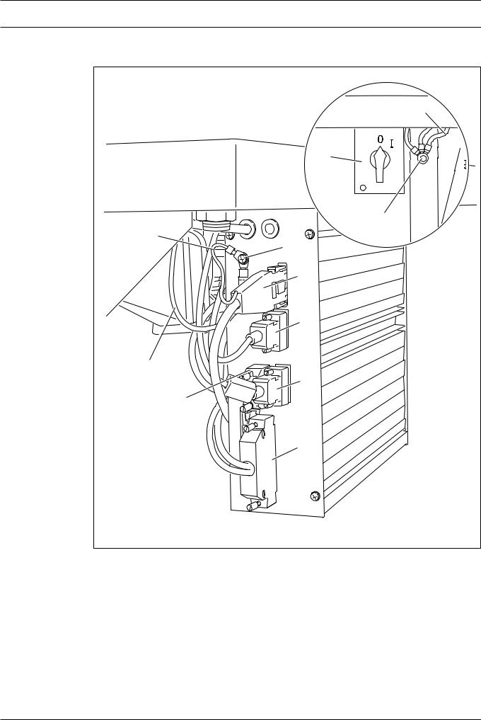
●Connect all the plugs1-5 to the control box as labelled.
●Screw the earth cable from the sewing head and from main switch6 to earth pointA.
●Connect earth pointA and earth pointB with earth cable7.
●Screw the earth cable8 from the motor to earth pointB.
8 - 4
Installation and commissioning
8.05 Commissioning
●Examine the machine, in particular the electric cables and pneumatic connection tubes for any damage.
●Clean the machine thoroughly and then oil it.
●Have qualified personnel check whether the machine can be operated with the available voltage and whether it is connected properly in the terminal box. If there are any irregularities do not operate the machine under any circumstances.
●When the machine is running, the balance wheel must turn towards the operator, see
Chapter8.07Basicpositionofthemachinedriveunit.
● Connect the machine to the compressed air system. The pressure gauge should show a pressure of 6 bar. If necessary, adjust the value, seeChapter11.05Checking/adjusting theairpressure.
1 |
2 |
Fig. 8 - 07 |
4 |
4 |
5 |
3 |
Fig. 8 - 08 |
●Before commissioning the machine remove plug1 from its hole and fill in oil up to marking2, seeChapter11.02Oilingthehook.
Plug1 serves as a safety device for transportation and should not be used
during sewing operations.
●Before commissioning the machine remove screw3 and fill in oil up to the marking (inspection glass on the front side of the machine), seeChapter11.03Oilingthezigzag
drive.
8.06 Switchingthemachineon/off
●Switch the machine on, seeChapter7.01Mainswitch.
●Carry out a test run.
8 - 5
Installation and commissioning
8.07 |
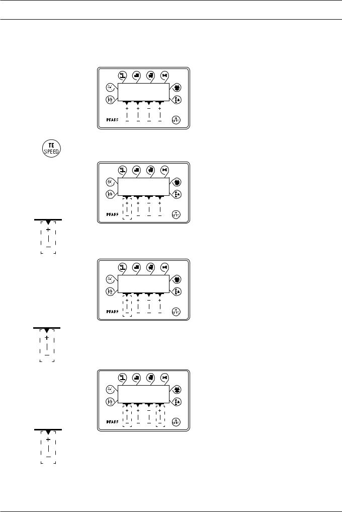
Basicsettingofthemachinedriveunit (only on machines with Quick-flange motor) |
● Switch on the machine.
3 3 3 3
A B C D
2 x |
● Press TE/Speed key twice to call up the input mode. |
TE
101 on
A
● By pressing the corresponding+/-key, call up parameter "798" and select service level
"C", seeChapter12.08.01Selectingtheuserlevel
TE
798 11
C
● By pressing the corresponding +/-key, call up parameter "800" (rotation direction of the motor).
● By pressing the corresponding +/-key enter the value "1".
TE
800 1
C
● By pressing the corresponding+/-key select parameter "700".
8 - 6
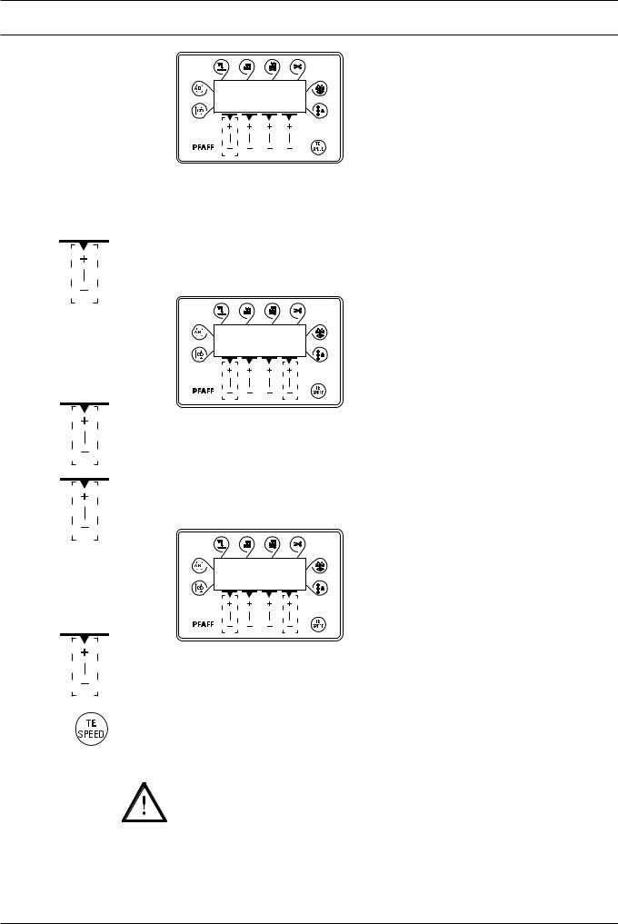
Installation and commissioning
TE
700 0
C
●Sew one stitch by operating the pedal.
●Turn the balance wheel in the direction of sewing until the tip of the needle is level with the top edge of the needle plate.
●By pressing the corresponding+/-key, select parameter "702".
TE
702 70
C
●By pressing the corresponding+/-key, enter the value "70".
●By pressing the corresponding+/-key, select parameter "703".
TE
703 222
C
●By pressing the corresponding+/-key, enter the value "222".
●Conclude the adjustment of the sewing motor by pressing theTE/Speed key.
The adjustment described above only applies to machines with Eco-Drive! When using another type of motor, please observe the motor instruction manual of the manufacturer.
8 - 7

Installation and commissioning |
|
|
8.08 |
Mounting/connectingthestartinhibitor (only on machines with Quick-flange motor) |
|
|
1 |
|
|
92-015 |
|
|
|
2 |
|
3 |
|
|
|
4 |
|
6 |
5 |
|
92013- |
|
|
Fig. 8 - 09 |
|
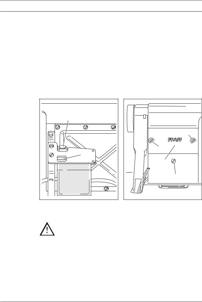
●For machines delivered without a table, the plate1 from the accessories should be mounted under the table top, so that the switch lug2 is resting on plate1 when the sewing head is in an upright position.
●Loosen screws3 and adjust switch 4 so that the switch lug2 is free when the sewing head is tilted back and pressed when the sewing head is upright.
●Connect plugs 5 and6 to the switch4.
Function check of the start inhibitor
ERROR
E 9
●Switch the machine on at the main switch and tilt it back. The error message "E9" must appear on the control panel.
●If the message does not appear, check the setting of switch 4.
●Set the sewing head upright and acknowledge the error message by pressing the TE/ Speed key. The machine is ready for operation again.
8 - 8
Setting up
9 Settingup
|
All instructions and regulations in this instruction manual must be observed. |
|
|
Special attention must be given to all safety regulations! |
|
|
All setting-up work must only be done by personnel with the necessary |
|
|
training. For all setting-up work the machine must be isolated from its power |
|
|
supply by turning off the on/off switch or removing the machine plug from the |
|
|
electric power socket! |
|
9.01 |
Insertingtheneedle |
|
|
|
Switch off the machine! |
|
|
Danger of injury if the machine |
|
|
is started accidentally! |
|
|
Only use needles of system 438. |
|
|
● Bring the needle bar into its highest |
|
|
position. |
|
1 |
● Loosen screw1. |
|
● Insert the needle2 as far as possible. |
|
|
|
|
|
|
● The long needle groove must be facing |
|
2 |
forwards. |
|
|
● Tighten screw1. |
|
Fig. 9 - 01 |
|
9 - 1
Setting up
9.02 Windingthebobbinthread;adjustingtheprimarythreadtension
|
4 |
- |
|
|
+ |
6 |
-018 |
|
|
92 |
|
5 |
|
|
|
3 |
1 |
|
|
|
|
2 |
|
Fig. 9 - 02 |
|
|
●Place an empty bobbin1 onto bobbin winder spindle2.
●Thread the bobbin as shown in Fig.9-02 and wind it clockwise around bobbin1 a few times.
●Switch on the bobbin winder while at the same time pressing bobbin winder spindle2 and lever3.
The bobbin is filled up during sewing.
●The thread tension on bobbin1 can be adjusted using knurled screw4.
●The bobbin winder stops automatically when bobbin1 is full.
If the thread is wound unevenly:
●Loosen nut5.
●Turn thread guide 6 accordingly.
●Tighten nut5.
9 - 2
 Loading...