


Mauser Spezial Series 40
MAUSER
SPEZIAL
Serie
40
Adjustment
instructions
Pfaff
Industriemaschinen
GmbH
675
Kaisersiautern
West-Germany
From the library of: Superior Sewing Machine & Supply LLC
MAUSER
SPEZiAl^
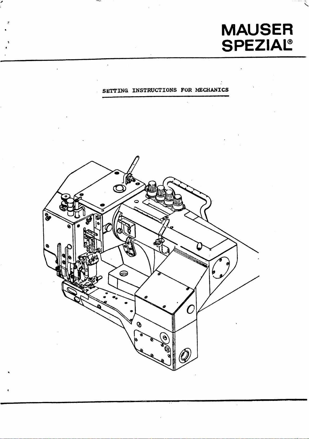
SETTING
INSTRUCTIONS
FOR
MECHANICS
From the library of: Superior Sewing Machine & Supply LLC
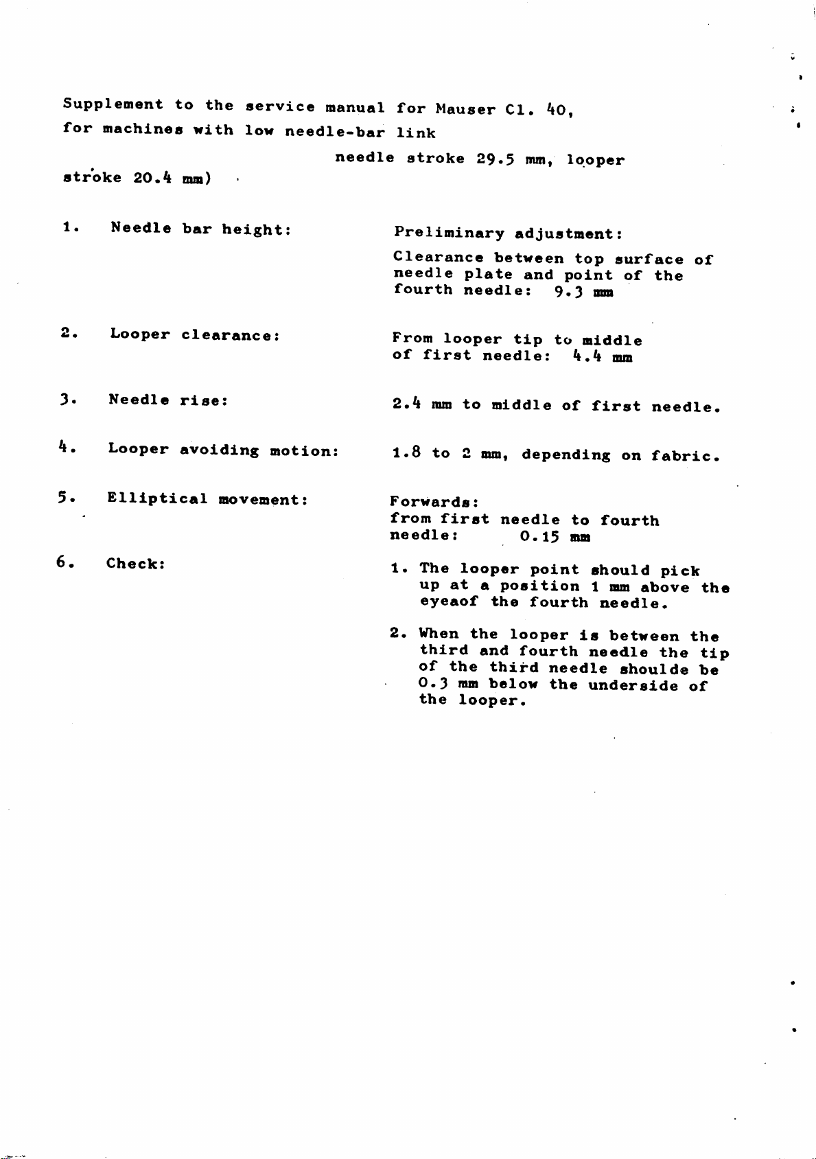
Supplement
to
the
service
manual
for
Mauser
Cl,
^0,
for
machines
with
low
needle-bar
link
needle
stroke
29*5
mm,
looper
stroke
20.4
mm)
1«
Needle
bar
height:
Looper
clearance:
3«
Needle
rise:
4.
Looper
avoiding
motion:
5*
Elliptical
movement:
6.
Check:
Preliminary
adjustment:
Clearance
between
top
surface
of
needle
plate
and
point
of
the
fourth
needle:
9.3
mm
From
looper
tip
to
middle
of
first
needle:
mm
2.^
nun
to
middle
of
first
needle.
1.8
to
2
mm,
depending
on
fabric.
Forwards:
from
first
needle
to
fourth
needle:
0.15
mm
1.
The
looper
point
should
pick
up
at
a
position
1 mm
above
the
eyeaof
the
fourth
needle.
2.
When
the
looper
is
between
the
third
and
fourth
needle
the
tip
of
the
third
needle
shoulde
be
0.3
ram
below
the
underside
of
the
looper.
From the library of: Superior Sewing Machine & Supply LLC
- 1 -
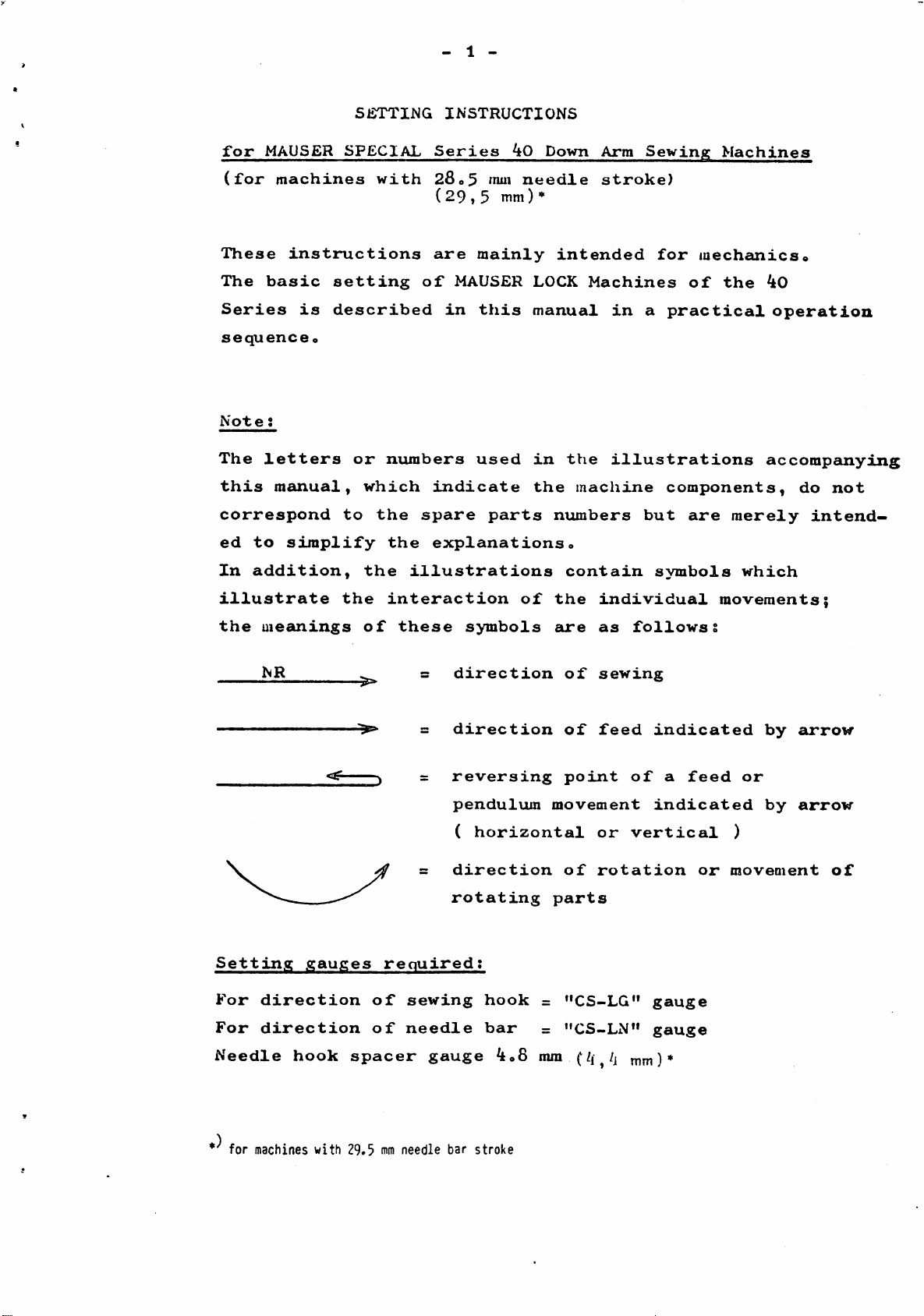
S12TTING
INSTRUCTIONS
for
MAUSER
SPECIAL
Series
kO
Down
Arm
Sewinja;
Machines
(for
machines
with
2Se5
mm
needle
stroke)
(29,5
mm)»
These
instructions
are
mainly
intended
for
mechanics«
The
basic
setting
of
MAUSER LOCK
Machines
of
the
kO
Series
is
described
in
this
manual
in
a
practical
operation
sequence
o
Note
s
The
letters
or
numbers
used
in
the
illustrations
accompanying
this
manual,
which
indicate
the
machine
components,
do
not
correspond
to
the
spare
parts
numbers
but
are
merely
intend
ed
to
simplify
the
explanationso
In
addition,
the
illustrations
contain
symbols
which
illustrate
the
interaction
of
the
individual
movements;
the
meanings
of
these
symbols
are
as
followss
NR
=
direction
of
sewing
=
direction
of
feed
indicated
by
arrow
reversing
point
of
a
feed
or
pendulum
movement
indicated
by
arrow
(
horizontal
or
vertical
)
direction
of
rotation
or
moveoient
of
rotating
parts
SettdLng
gauges
required;
For
direction
of
sewing
hook
=
"CS-LG"
gauge
For
direction
of
needle
bar
=
"CS-LN"
gauge
Needle
hook
spacer
gauge
^08
mm
mm)*
for
machines
with
29.5
mm
needle
bar
stroke
From the library of: Superior Sewing Machine & Supply LLC
- 2 -
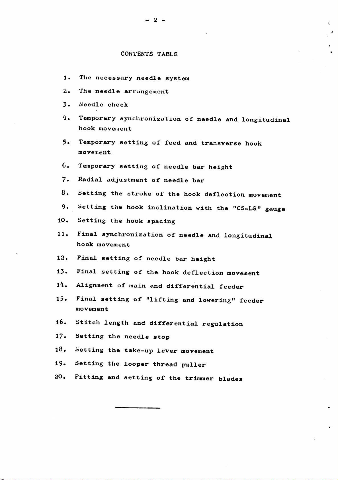
CONTENTS
TABLE
1.
Tlie
necessary
needle
system
2*
The
needle
arrangement
3«
Needle
check
4.
Temporary
synchronization
of
needle
and
longitudinal
hook
movement
5*
Temporary
setting
of
feed
and
transverse
hook
movement.
6.
Temporary
setting
of
needle
bar
height
7»
Radial
adjustment
of
needle
bar
8»
Setting
the
stroke
ot
the
hook
deflection
movement
9*
Setting
the
hook
inclination
vritlx
the
"CS-LG" gauge
10*
Setting
the
hook
spacing
11.
Final
synchronization
of
needle
and
longitudinal
hook
movement
12.
Final
setting
of
needle
bar
height
13*
Final
setting
of
the
hook
deflection
movement
l4.
Alignment
of
main
and
differential
feeder
15*
Final
setting
of
"lifting
and
lowering"
feeder
movement
16.
Stitch
length
and
differential
regulation
17.
Setting
the
needle
stop
l8•
Setting
the
take—up
lever
movement
19*
Setting
the
looper
thread
puller
20.
Fitting
and
setting
of
the
trimmer
blades
From the library of: Superior Sewing Machine & Supply LLC
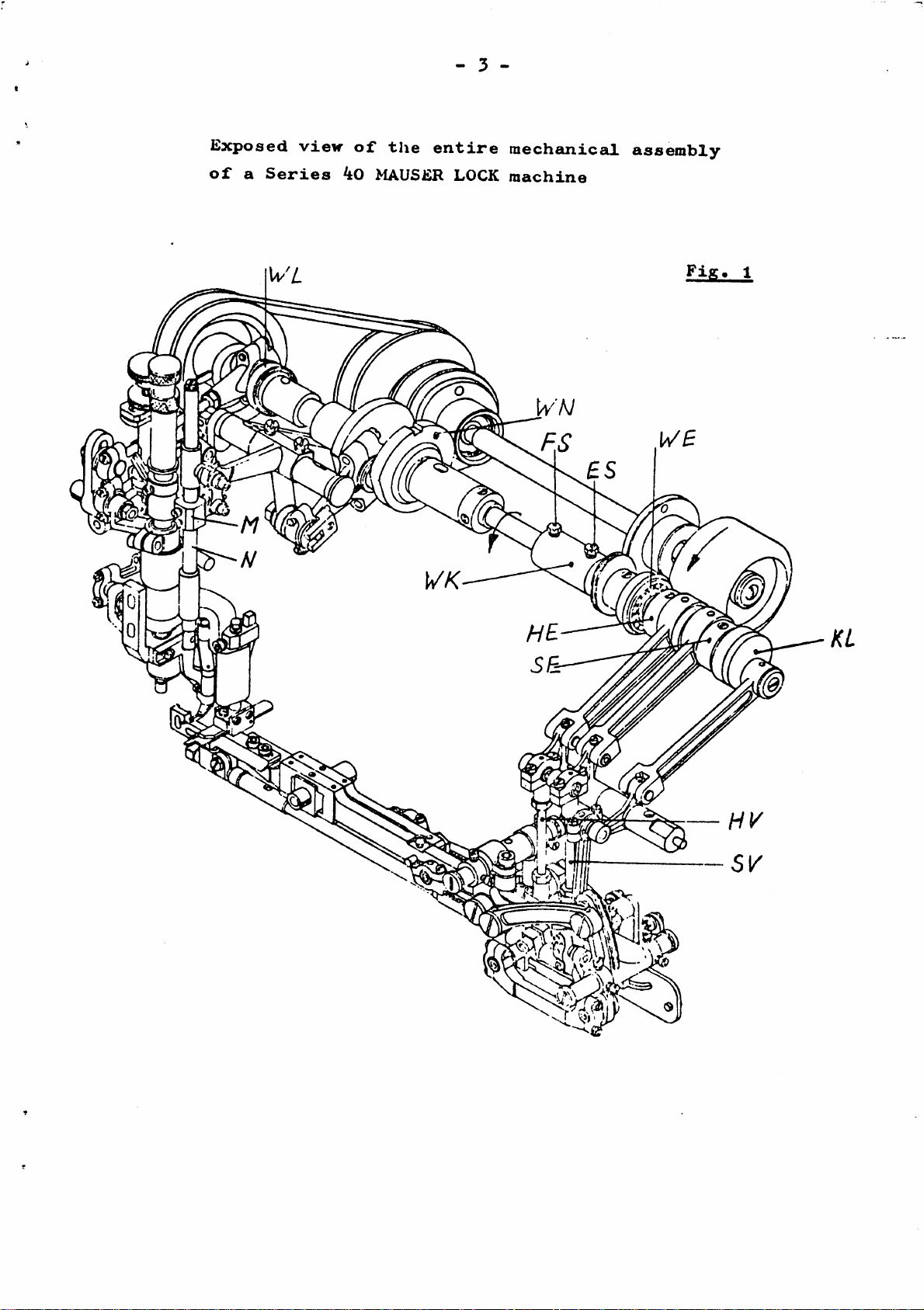
- 3 -
Lxposed
view
of
the
entire
mechanicaJL
assembly
of
a
Series
40
MAUSiiR LOCK
machine
Fig
From the library of: Superior Sewing Machine & Supply LLC
My
1014
B
My.1014
C
iZ^ZZZZ^
Y
Mv
1014
D
- 4 -
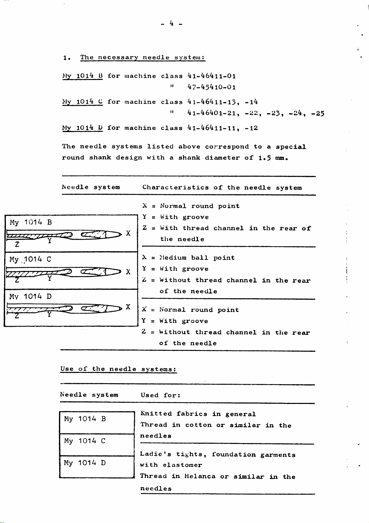
1•
The
necessary
needle
system:
My
10i3
for
machine
class
4l-464ll-01
"
47-45410-01
My
1014
C
for
machine
class
4l-464ll-l5,
-l4
"
4i-46401-21,
-22,
-23,
-24,
-25
My
10l4
D
for
machine
class
4l-464ll-ll,
-12
The
needle
systems
listed
above
correspond
to
a
special
round
shank
design
with
a
shank
diameter
of
1.5
nun.
Needle
system
Characteristics
of
the
needle
system
X =
Normal
round
point
Y =
With
groove
Z =
With
thread
channel
in
the
rear
of
the
needle
X =
Medium
ball
point
Y =
With
groove
Z =
Without
thread
channel
in
the
rear
of
the
needle
X =
Normal
round
point
Y =
With
groove
Z =
Without
thread
channel
in
the
rear
of
the
needle
Use
of
the
needle
systems;
Needle
system
My
1014
B
My
1014
C
My
1014
D
1
Used
for:
Knitted
fabrics
in
general
Thread
in
cotton
or
similar
in
the
needles
Ladie's
tights,
foundation
garments
with
elastomer
Thread
in
Helanca
or
simileu*
in
the
needles
From the library of: Superior Sewing Machine & Supply LLC

- 5 -
3•
Needle
check
Only
new
needles
must
be
used
for
setting
up
the
machine.
To
avoid
all
risks,
the
needles
must
be
checked
for
straight
running
before
use
by
rolling
them
on
a
flat
surface
(fig.
3).
k•
Temporary
synchronization
of
needle
and
longitudinal
hook
movement
The
mechanism
for
the
feeder
and
longitudinal
hook
move
ment
situated
in
the
suj)port
arm
of
the
machine
is
controlled
by
tlie
drive
shaft
"WE",
which
is
adjustably
connected
to
the
needle
drive
shaft
"WN"
by
means
of
the
shaft
coupling
"WK"
(fig.
l).
The
crank
"KL"
(for
the
drive
of
the
longitudinal
hook
movement)
is
firmly
connected
to
the
drive
shaft
"WE"
(fig.
l)
.
Tlie
synchronization
of
the
needle
and
longitudinal
hook
movement
CcUi
therefore
only
be
set
at
the
shaft
coupling
I
The
basic
adjustment
of
a,
for
exsimple,
completely
unadjusted
machine
starts
first
with
the
temporary
syn
chronization
of
the
needle
movement
\>rita
the
longitudinal
hook
movement«
Fig.
4
From the library of: Superior Sewing Machine & Supply LLC
- 6 -
Sett
ing:
Helease
pair
of
screws
"£S"«
Align
the
groove
"N"
with
the
fixing
screw
"FS"
by
a
corresponding
rotation
of
the
shaft
"WE"
(fig.
^)o
Note:
The
fixing
screw
"FS"
(1st
screw
in
the
direction
of
rotation)
is
located
on
a
surface
of
the
shaft
"WN"
(fig*
4).
Final
setting:
(see
Point
ll).
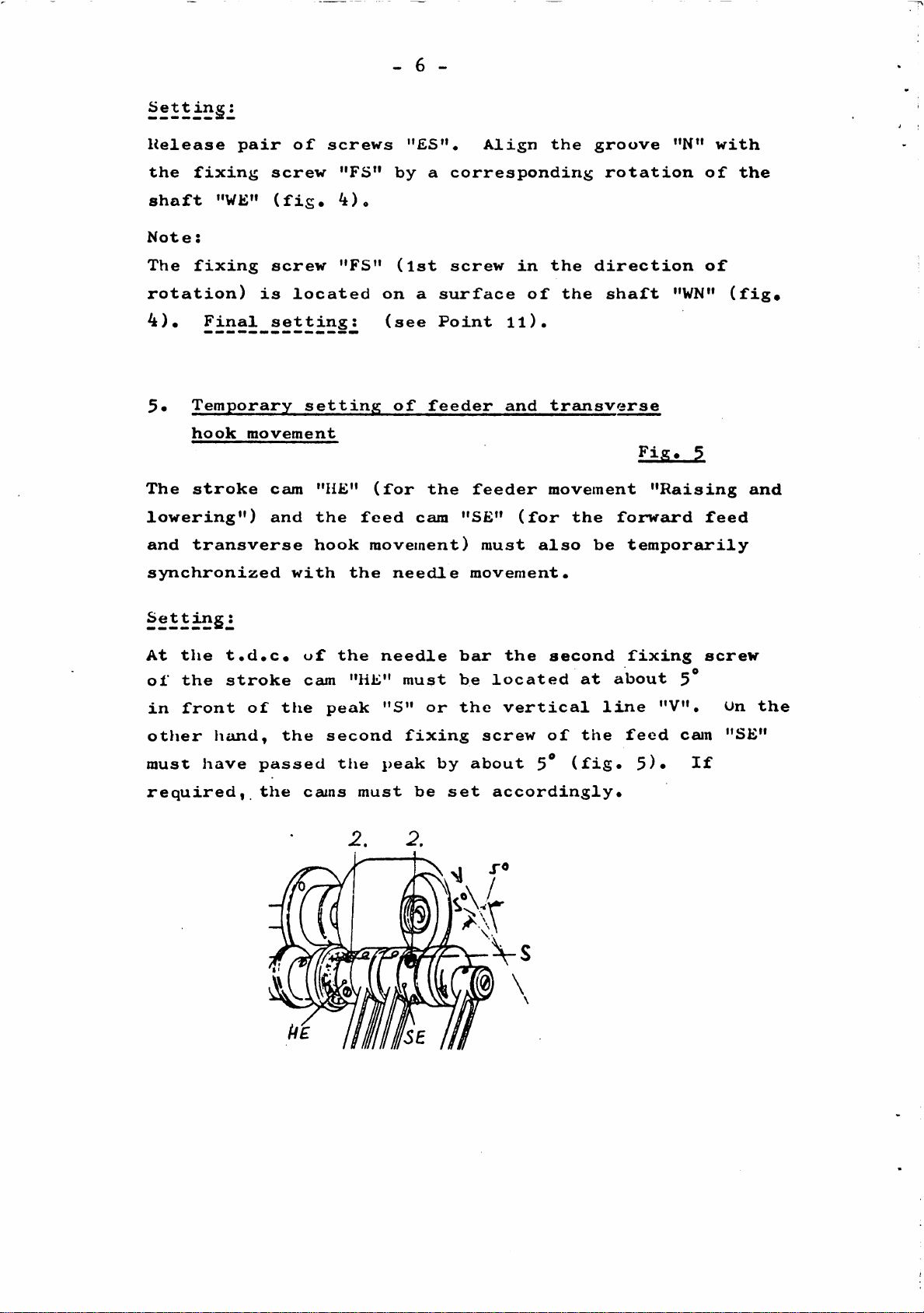
5*
Temporary
setting
of
feeder
and
transverse
hook
movement
£i£.
The
stroke
cam
"HE"
(for
the
feeder
movement
"Raising
and
lowering")
and
the
feed
cam
"SE"
(for
the
forward
feed
and
transverse
hook
movement)
must
also
be
temporarily
synchronized
with
the
needle
movement.
Setting:
At
the
t.d.c.
uf
the
needle
bar
the
second
fixing
screw
of
the
stroke
cam
"HE"
must
be
located
at
about
5*
in
front
of
the
peak
"S"
or
the
vertical
line
"V",
On
the
otJier
hcUid,
the
second
fixing
screw
of
the
feed
cam
"SE"
must
have
passed
tlie
peak
by
about
5^
(fig.
5)*
If
required,
the
cams
must
be
set
accordingly.
s
From the library of: Superior Sewing Machine & Supply LLC
- 7 -
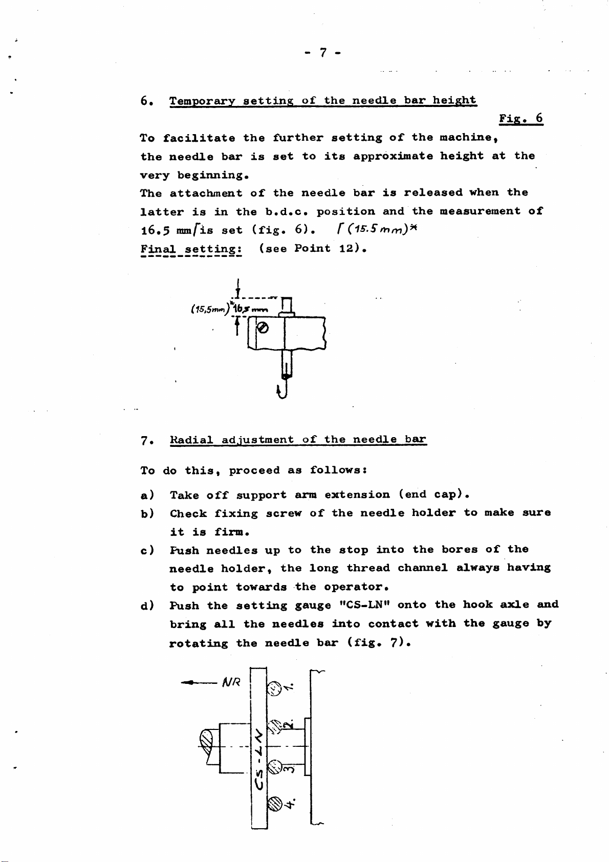
6*
Temporary
setting
of
the
needle
bar
height
Fig^
6
To
facilitate
the
further
setting
of
the
machine«
the
needle
bar
is
set
to
its
approximate
height
at
the
very
beginning*
The
attachment
of
the
needle
bar
is
released
when
the
latter
is
in
the
b.d.c*
position
and
the
measurement
of
l6*5
mm/"is
set
(fig*
6)* f
Final
setting:
(see
Point
12)*
C
15,5nvn^
T
]
7•
Radial
adjustment
of
the
needle
bar
To
do
this,
proceed
as
follows:
a)
Take
off
support
arm
extension
(end
cap)*
b)
Check
fixing
screw
of
the
needle
holder
to
make
sure
it
is
firm*
c)
Push
needles
up
to
the
stop
into
the
bores
of
the
needle
holder,
the
long
thread
channel
always
having
to
point
towards
the
operator*
d)
Push
the
settdLng
gauge
"CS-LN"
onto
the
hook
axle
and
bring
all
the
needles
dlnto
contact
with
the
gauge
by
rotating
the
needle
bcur
(fig*
?)•
A//?
n
From the library of: Superior Sewing Machine & Supply LLC
 Loading...