


471
474
Instruction Manual
491
This instruction manual applies to machines from the
following serial numbers onwards:
PFAFF 471 # 2560474
PFAFF 474 # 2561194
PFAFF 491 # 2561421 
296-12-18 398/002 Betriebsanleitung engl. 12.99
Downloaded from www.Manualslib.com manuals search engine

This instruction manual applies to all versions and subclasses listed under "Specifications".
Reprinting, copying or translation of PFAFF instruction manuals, whether in whole or in part, is not permitted without our prior permission and not without written indication of the source.
G.M. PFAFF KAISERSLAUTERN
INDUSTRIEMASCHINEN AG
Postfach 3020
D-67653 Kaiserslautern
Königstr. 154
D-67655 Kaiserslautern
Editing/illustrations
Verlag TD
D-77901 Lahr
Downloaded from www.Manualslib.com manuals search engine

Index
|
Contents .................................................................................. |
Chapter - Page |
|||
1 |
Safety ............................................................................................................................ |
|
1 |
- |
1 |
1.01 |
Directives ...................................................................................................................... |
|
1 |
- |
1 |
1.02 |
General notes on safety ................................................................................................. |
|
1 |
- |
1 |
1.03 |
Safety symbols ............................................................................................................. |
|
1 - |
2 |
|
1.04 |
Important points for the user.......................................................................................... |
|
1 |
- |
2 |
1.05 |
Operating and specialist personnel ................................................................................ |
|
1 |
- |
3 |
1.05.01 |
Operating personnel ....................................................................................................... |
|
1 |
- |
3 |
1.05.02 |
Specialist personnel ....................................................................................................... |
|
1 |
- |
3 |
1.06 |
Danger ........................................................................................................................... |
|
1 |
- |
4 |
2 |
Proper use .................................................................................................................... |
|
2 |
- |
1 |
3 |
Specifications .............................................................................................................. |
|
3 - |
1 |
|
3.01 |
PFAFF 471, 474, 491 ..................................................................................................... |
|
3 - |
1 |
|
3.02 |
Needles and threads ...................................................................................................... |
|
3 - |
2 |
|
3.03 |
Possible models and subclasses................................................................................... |
|
3 |
- |
2 |
4 |
Disposal of Machine .................................................................................................... |
|
4 - |
1 |
|
5 |
Transportation, packing and storage ......................................................................... |
|
5 |
- |
1 |
5.01 |
Transportation to customer's premises ......................................................................... |
|
5 |
- |
1 |
5.02 |
Transportation inside the customer's premises ............................................................. |
|
5 - |
1 |
|
5.03 |
Disposal of packing materials ........................................................................................ |
|
5 |
- |
1 |
5.04 |
Storage .......................................................................................................................... |
|
5 |
- |
1 |
6 |
Explanation of symbols ............................................................................................... |
|
6 |
- |
1 |
7 |
Controls........................................................................................................................ |
|
7 |
- |
1 |
7.01 |
On / off switch on machines with mini-stop motor |
|
|
|
|
|
without edge trimmer -725/.. or -726/.. .......................................................................... 7 |
- |
1 |
||
7.02 |
On / off switch on machines with mini-stop motor |
|
|
|
|
|
and edge trimmer -725/.. or -726/.. ................................................................................ 7 |
- |
1 |
||
7.03 |
Button on machine head (only on machines with -911/..) ............................................. |
|
7 |
- |
2 |
7.04 |
Pedal ............................................................................................................................. |
|
7 |
- |
2 |
7.05 |
Lever for lifting roller presser.......................................................................................... |
|
7 |
- |
3 |
7.06 |
Knee lever ..................................................................................................................... |
|
7 |
- |
3 |
7.07 |
Key for setting stitch length ........................................................................................... |
|
7 |
- |
4 |
7.08 |
Swing out roller presser ................................................................................................. |
|
7 |
- |
4 |
7.09 |
Edge trimmer -725/04 for 471 ....................................................................................... |
|
7 |
- |
5 |
7.10 |
Edge trimmer -725/04 for 474 and 491 .......................................................................... |
|
7 |
- |
6 |
7.11 |
Edge trimmer -726/05 for 491 ........................................................................................ |
|
7 |
- |
7 |
8 |
Installation and commissioning ................................................................................. |
|
8 |
- |
1 |
8.01 |
Installation ..................................................................................................................... |
|
8 |
- |
1 |
8.01.01 |
Adjusting the table height .............................................................................................. |
|
8 |
- |
1 |
8.01.02 |
Fitting the tilt lock .......................................................................................................... |
|
8 |
- |
2 |
8.01.03 |
Tensioning the v-belt (does not apply to machines with mini-stop motor) ...................... |
|
8 |
- |
2 |
8.01.04 |
Fitting the v-belt guard ................................................................................................... |
|
8 |
- |
3 |
8.01.05 |
Fitting the bottom v-belt guard (does not apply to machines with mini-stop motor) ....... |
8 - |
3 |
||
8.01.06 |
Fitting the synchronizer .................................................................................................. |
|
8 |
- |
4 |
8.01.07 |
Fitting the reel stand ...................................................................................................... |
|
8 |
- |
4 |
8.02 |
Commissioning ............................................................................................................. |
|
8 |
- |
5 |
|
|
|
|
|
|
Downloaded from www.Manualslib.com manuals search engine

Index
|
Contents .................................................................................. |
Chapter - Page |
|||
8.03 |
Switching the machine on / off ...................................................................................... |
|
8 |
- |
5 |
9 |
Setting up ..................................................................................................................... |
|
9 |
- |
1 |
9.01 |
Inserting the needle on model 471 and 491.................................................................... |
|
9 - |
1 |
|
9.02 |
Inserting the needle on model 474 ................................................................................. |
|
9 |
- |
2 |
9.03 |
Winding the bobbin thread; adjusting the primary thread tension ................................... |
|
9 |
- |
3 |
9.04 |
Removing / Inserting the bobbin case ............................................................................ |
|
9 - |
4 |
|
9.05 |
Threading the bobbin case / Adjusting the bobbin thread tension ................................... |
|
9 - |
4 |
|
9.06 |
Threading the needle thread and regulating its tension on model 471/491 ...................... |
|
9 - |
5 |
|
9.07 |
Threading the needle thread and regulating its tension on model 474 ............................. |
|
9 - |
6 |
|
9.08 |
Setting the stitch length ................................................................................................. |
|
9 |
- |
7 |
10 |
Care and maintenance ................................................................................................ |
|
10 - |
1 |
|
10.01 |
Cleaning ....................................................................................................................... |
|
10 |
- |
1 |
10.02 |
Oiling the hook ............................................................................................................. |
|
10 |
- |
2 |
10.03 |
Filling the oil reservoir of the thread lubrication unit ....................................................... |
|
10 |
- |
3 |
10.04 |
Lubricating the bevel gears ........................................................................................... |
|
10 - |
3 |
|
10.05 |
Checking / adjusting the air pressure ............................................................................ |
|
10 - |
4 |
|
10.06 |
Cleaning the air filter of the air-filter / lubricator ............................................................. |
|
10 |
- |
4 |
11 |
Adjustment .................................................................................................................. |
|
11 |
- |
1 |
11.01 |
Notes on adjustment .................................................................................................... |
|
11 - |
1 |
|
11.02 |
Tools, gauges and other accessories ............................................................................ |
|
11 - |
1 |
|
11.03 |
Abbreviations ................................................................................................................ |
|
11 |
- |
1 |
11.04 |
Adjusting the basic machine ..................................................................................... |
|
11 - |
2 |
|
11.04.01 |
Adjusting the synchronizer ............................................................................................ |
|
11 |
- |
2 |
11.04.02 |
Needle position in sewing direction on the PFAFF 471 and 491..................................... |
|
11 |
- |
3 |
11.04.03 |
Needle position in sewing direction on the PFAFF 474 .................................................. |
|
11 |
- |
4 |
11.04.04 |
Preliminary adjustment of the needle height ................................................................. |
|
11 |
- |
5 |
11.04.05 |
Needle rise, hook clearance, needle height and needle guard on the PFAFF 471 ........... |
11 |
- |
6 |
|
11.04.06 |
Needle rise, hook clearance, needle height and needle guard on the PFAFF 474 ........... |
11 |
- |
8 |
|
11.04.07 |
Needle rise, hook clearance, needle height and needle guard on the PFAFF 491 ........... |
11 |
- 10 |
||
11.04.08 |
Needle position crosswise to sewing direction on the PFAFF 471 ................................. |
|
11 |
- 12 |
|
11.04.09 |
Needle position crosswise to sewing direction on the PFAFF 474 ................................. |
|
11 |
- 13 |
|
11.04.10 |
Needle position crosswise to sewing direction on the PFAFF 491 ................................. |
|
11 |
- 14 |
|
11.04.11 |
Height of the bobbin-case opener.................................................................................. |
|
11 |
- 15 |
|
11.04.12 |
Bobbin-case opener stroke ........................................................................................... |
|
11 |
- 16 |
|
11.04.13 |
Height of the feed wheel on the PFAFF 471 .................................................................. |
|
11 |
-17 |
|
11.04.14 |
Height of the feed wheel on the PFAFF 474 .................................................................. |
|
11 |
- 18 |
|
11.04.15 |
Height of the feed wheel on the PFAFF 491 .................................................................. |
|
11 |
- 19 |
|
11.04.16 |
Stitch length control eccentric ....................................................................................... |
|
11 |
-20 |
|
11.04.17 |
Stitch length scale disk ................................................................................................. |
|
11 |
- 21 |
|
11.04.18 |
Shaft crank to feed wheel drive .................................................................................... |
|
11 |
- 22 |
|
11.04.19 |
Shaft crank to roller presser drive ................................................................................. |
|
11 |
- 23 |
|
11.04.20 |
Clearance between roller presser and feed wheel ......................................................... |
|
11 |
- 24 |
|
11.04.21 |
Roller presser ............................................................................................................... |
|
11 |
- 25 |
|
11.04.22 |
Stitch length on stitch length scale ............................................................................... |
|
11 |
- 26 |
|
11.04.23 |
Synchronization of roller presser and feed wheel .......................................................... |
|
11 |
- 27 |
|
11.04.24 |
Retainer (only on model 474) ........................................................................................ |
|
11 |
- 28 |
|
11.04.25 |
Knee lever .................................................................................................................... |
|
11 |
- 29 |
|
|
|
|
|
|
|
Downloaded from www.Manualslib.com manuals search engine

Index
|
Contents .................................................................................. |
Chapter - Page |
||
11.04.26 |
Needle thread tension release ....................................................................................... |
|
11 |
- 30 |
11.04.27 |
Thread check spring ..................................................................................................... |
|
11 |
- 31 |
11.04.28 |
Bobbin winder .............................................................................................................. |
|
11 |
- 32 |
11.04.29 |
Pressure of roller presser .............................................................................................. |
|
11 |
- 33 |
11.04.30 |
Re-engage safety coupling ........................................................................................... |
|
11 - 34 |
|
11.05 |
Adjusting the edge trimmer -725/04 ........................................................................... |
|
11 - 35 |
|
11.05.01 |
Position knife holder on model 471 ............................................................................... |
|
11 |
- 35 |
11.05.02 |
Position knife holder on models 474 and 491 ................................................................ |
|
11 |
- 36 |
11.05.03 |
Knife stroke on model 471 ............................................................................................ |
|
11 |
- 37 |
11.05.04 |
Knife stroke on models 474 and 491 ............................................................................. |
|
11 |
- 38 |
11.05.05 |
Cutting stroke on model 471 ........................................................................................ |
|
11 |
- 39 |
11.05.06 |
Cutting stroke on models 474 and 491.......................................................................... |
|
11 |
- 40 |
11.05.07 |
Knife position ................................................................................................................ |
|
11 |
- 41 |
11.06 |
Adjusting the thread trimmer -726/05 on model 491 ................................................ |
|
11 |
- 42 |
11.06.01 |
Position of the knife to the needle plate ........................................................................ |
|
11 |
- 42 |
11.06.02 |
Knife position crosswise to sewing direciton ................................................................ |
|
11 |
- 43 |
11.06.03 |
Knife height .................................................................................................................. |
|
11 |
- 44 |
11.06.04 |
Cutting stroke ............................................................................................................... |
|
11 |
- 45 |
11.06.05 |
Knife stroke .................................................................................................................. |
|
11 |
- 46 |
11.07 |
Adjusting the thread trimmer -900/53 ........................................................................ |
|
11 - 47 |
|
11.07.01 |
Removing the cutter ..................................................................................................... |
|
11 |
- 47 |
11.07.02 |
Control cam with respect to bobbin opener and tripping lever ....................................... |
|
11 |
- 48 |
11.07.03 |
Radial position of the tripping lever ............................................................................... |
|
11 |
- 49 |
11.07.04 |
Engaging solenoid ......................................................................................................... |
|
11 |
- 50 |
11.07.05 |
Cutter drive lever .......................................................................................................... |
|
11 |
- 51 |
11.07.06 |
Control cams for bobbin opener and cutter (using adjustment gauge) ........................... |
|
11 |
- 52 |
11.07.07 |
Radial position of the control cam in relation to the bobbin opener ................................ |
|
11 |
- 53 |
11.07.08 |
Control cam for cutter (adjustment without gauge) ....................................................... |
|
11 |
- 54 |
11.07.09 |
Cutter control lever for the control cam of the cutter ..................................................... |
|
11 |
- 55 |
11.07.10 |
Cutter return lever ......................................................................................................... |
|
11 |
- 56 |
11.07.11 |
Cutter return control ...................................................................................................... |
|
11 |
- 57 |
11.07.12 |
Fitting the cutter ............................................................................................................ |
|
11 |
- 58 |
11.07.13 |
Eccentric sleeve ........................................................................................................... |
|
11 |
- 59 |
11.07.14 |
Cutter driving rod .......................................................................................................... |
|
11 |
- 60 |
11.07.15 |
Cutter function test ....................................................................................................... |
|
11 |
- 61 |
11.08 |
Tension release (only on machines with thread tension control -906/10) ............... |
11 - 63 |
||
11.09Adjustment of backtacking mechanism -911/.. .........................................................11 - 64
11.09.01 |
Needle in needle hole (only for PFAFF 471 and 491) ..................................................... |
11 |
- 64 |
11.09.02 |
Coupling for roller presser drive .................................................................................... |
11 |
- 65 |
11.09.03 |
Bevel gears for feed wheel drive (on the PFAFF 471 and 474) ...................................... |
11 |
- 66 |
11.09.04 |
Bevel gear play (on the PFAFF 471 and 474) ................................................................ |
11 |
- 67 |
11.09.05 |
Bevel gears for feed wheel drive (on the PFAFF 491).................................................... |
11 |
- 68 |
11.09.06 |
Bevel gear play (on the PFAFF 491) .............................................................................. |
11 |
- 69 |
11.10 |
Parameter settings for the Quick-Ministop Motor ..................................................... |
11 - 70 |
|
Downloaded from www.Manualslib.com manuals search engine

Safety
1 Safety
1.01Directives
This machine is constructed in accordance with the European regulations contained in the conformity and manufacturer’s declarations.
In addition to this Instruction Manual, observe also all generally accepted, statutory and other regulations and legal requirements and all valid environmental protection regulations! The regionally valid regulations of the social insurance society for occupational accidents or other supervisory organisations are to be strictly adhered to!
1.02 General notes on safety
●This machine may only be operated by adequately trained operators and only after the Instruction Manual has been completely read and understood!
●All Notes on Safety and Instruction Manuals of the motor manufacturer are to be read before operating the machine!
●The danger and safety instructions on the machine itself are to be followed!
●This machine may only be used for the purpose for which it is intended and may not be operated without its safety devices. All safety regulations relevant to its operation are to be adhered to.
●When exchanging sewing tools (e.g. needle, roller presser, needle plate or bobbin), when threading the machine, when leaving the machine unattended and during maintenance work, the machine is to be separated from the power supply by switching off the On/Off switch or by removing the plug from the mains!
●Everyday maintenance work is only to be carried out by appropriately trained personnel!
●Repairs and special maintenance work may only be carried out by qualified service staff or appropriately trained personnel!
●Work on electrical equipment may only be carried out by appropriately trained personnel!
●Work is not permitted on parts and equipment which are connected to the power supply! Exceptions to this are only to be found in the regulations EN 50110.
●Modifications and alterations to the machine may only be carried out under observance of all the relevant safety regulations!
●Only spare parts which have been approved by us are to be used for repairs! We expressly point out that any replacement parts or accessories, which are not supplied by us, have not been tested and approved by us. The installation and/or use of any such products can lead to negative changes in the structural characteristics of the machine. We shall not be liable for any damage which may be caused by non-original parts.
1 - 1
Downloaded from www.Manualslib.com manuals search engine
Safety
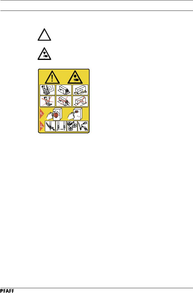
1.03 |
Safety symbols |
Danger!
!Points to be observed.
Danger of injury for operating and specialist personnel!
Caution
Do not operate without finger guard and safety devices. Before threading, changing bobbin and needle, cleaning etc. switch off main switch.
 I
I
1.04 Important points for the user
● This Instruction Manual is a component part of the machine and must be available to the operating personnel at all times.
● The Instruction Manual must be read before operating the machine for the first time.
● The operating and specialist personnel is to be instructed as to the safety equipment of the machine and regarding safe work methods.
● It is the duty of the user to only operate the machine in perfect running order.
● It is the obligation of the user to ensure that none of the safety mechanisms are removed or deactivated.
● It is the obligation of the user to ensure that only authorized persons operate and work on the machine.
Further information can be obtained from your PFAFF agent.
1 - 2
Downloaded from www.Manualslib.com manuals search engine

Safety
1.05Operating and specialist personnel
1.05.01 Operating personnel
Operating personnel are persons responsible for the equipping, operating and cleaning of the machine as well as taking care of faults arising in the sewing area.
The operating personnel is obliged to observe the following points and must:
●always observe the Notes on Safety in the Instruction Manual!
●never use any working methods which could limit the level of safety in using the machine!
●not wear loose-fitting clothing or jewellery such as chains or rings!
●also ensure that only authorized persons have access to the potentially dangerous area around the machine!
●always immediately report to the person responsible any changes in the machine which may limit its safety!
1.05.02 Specialist personnel
Specialist personnel are persons with a specialist education in the fields of electrics, electronics and mechanics. They are responsible for the lubrication, maintenance, repair and adjustment of the machine.
The specialist personnel is obliged to observe the following points and must:
●always observe the Notes on Safety in the Instruction Manual!
●switch off the On/Off switch before carrying out adjustments or repairs and ensure that it cannot be switched on again unintentionally!
●never work on parts which are still connected to the power supply! Exceptions are contained only in the regulations EN 50110.
●replace the protective coverings and close the electrical control box after all repairs or maintenance work!
1 - 3
Downloaded from www.Manualslib.com manuals search engine

Safety
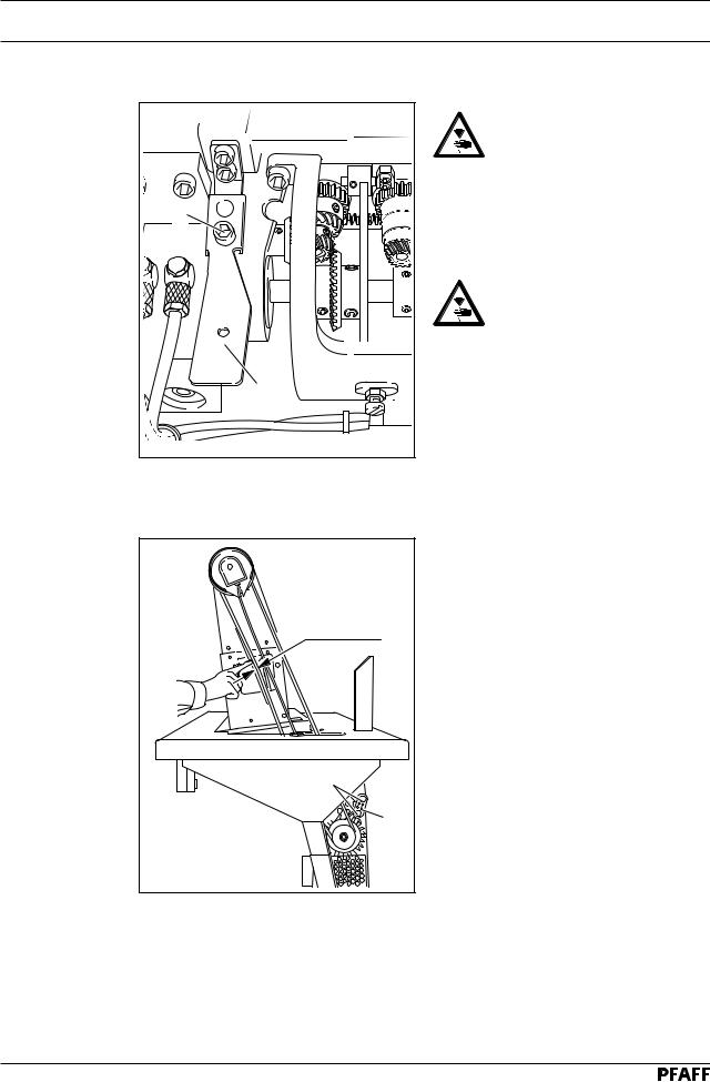
1.06 Danger
A working area of 1 meter is to be kept free both in front of and behind the machine while it is in operation so that it is always easily accessible.
Never reach into the sewing area while sewing! Danger of injury by the needle!
Never leave objects on the table while adjusting the machine settings!
Objects can become trapped or be slung away! Danger of injury!
Switch the machine off before tilting it backwards!
Danger of injury if the machine is started accidentally!
2 |
4 |
|
|
3 |
|
1 |
|
6 |
5 |
|
|
Fig. 1 - 01 |
|
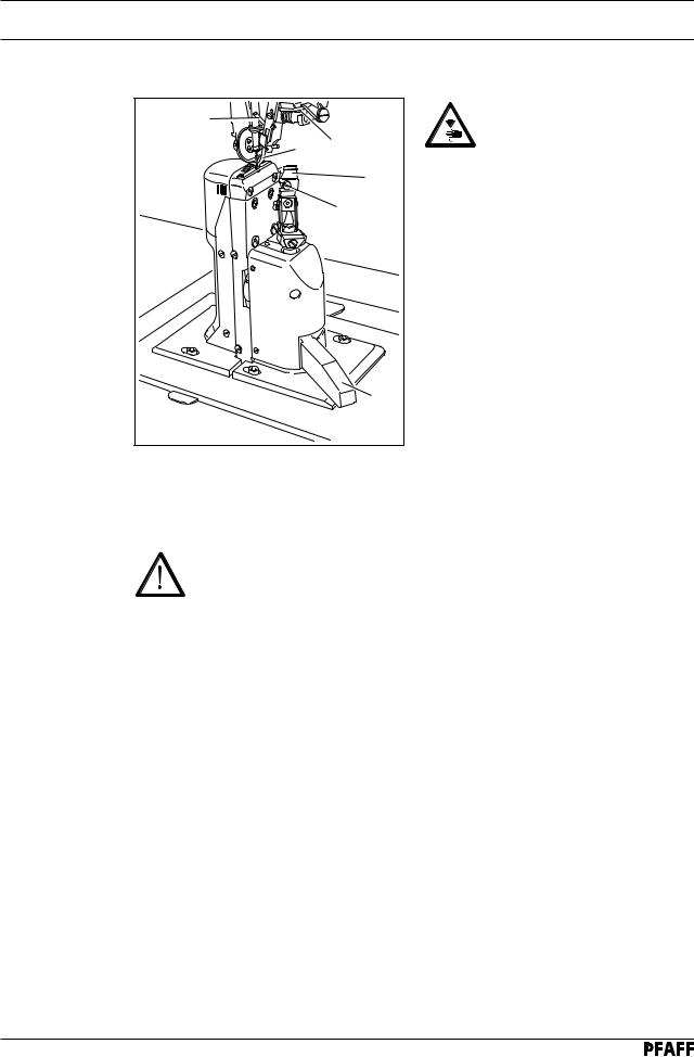
Do not operate the machine without support 1! Danger due to top-heavy sewing head! Machine can tip over backwards when tilted!
Do not operate the machine without its take-up-lever guard 2!
Danger of injury due to the motion of the take-up lever!
On machines with thread lubricator, only operate the machine with the eye guard 3 lowered!
The eye guard 3 protects the eyes from oil particles from the thread lubrication.
Do not operate the machine without belt guard 4 and 5!
Danger of injury by rotating drive belt!
Do not operate the machine without tilt lock 6!
Danger of crushing between sewing head and table top!
1 - 4
Downloaded from www.Manualslib.com manuals search engine

Proper use
2 |
Proper use |
|
|
The PFAFF 471 |
is a single needle, high-speed post bed sewing machine (post to the left |
|
|
of the needle) with driven feed wheel and roller presser and synchronized |
|
|
needle. |
|
The PFAFF 474 |
is a two-needle, high-speed post bed sewing machine with driven feed |
|
|
wheel and roller presser |
|
The PFAFF 491 |
is a single needle, high-speed post bed sewing machine (post to the right |
|
|
of the needle) with driven feed wheel and roller presser and synchronized |
|
|
needle. |
The machines are used for sewing lockstitch seams in the leather and upholstery industries.
Any use of these machines which is not approved by the manufacturer shall be considered as improper use! The manufacturer shall not be liable for any damage arising out of improper use! Proper use shall also be considered to include compliance with the operation, adjustment, service and repair measures specified by the manufacturer!
2 - 1
Downloaded from www.Manualslib.com manuals search engine
|
|
|
Specifications |
3 |
Specifications |
|
|
3.01 |
PFAFF 471, 474 , 491 ▲ |
|
|
|
Stitch type: .................................................................................................. |
301 (lockstitch) |
|
|
Balance wheel eff. diameter: .................................................................................... |
65 mm |
|
|
Fabric clearance (roller presser raised): ...................................................................... |
7 mm |
|
|
Clearance width: .................................................................................................... |
245 mm |
|
|
Clearance height: .................................................................................................... |
115 mm |
|
|
Post height: ............................................................................................................ |
180 mm |
|
|
Dimensions of sewing head: |
|
|
|
Length: ....................................................................................................... |
approx. 615 mm |
|
|
Width: ......................................................................................................... |
approx. 240 mm |
|
|
Height (above table): ................................................................................... |
approx. 450 mm |
|
|
Size of bedplate: ............................................................................................ |
518 x 177 mm |
|
|
Max. speed: |
|
|
|
Model A + B......................................................................................... |
2800 stichtes/min |
|
|
Model B/C ............................................................................................ |
2500 stichtes/min |
|
|
Trimming margin (for -725/.. and -726/..): ....................................................... |
0.8 - 2.5 mm |
|
|
Trimming speed (for -725/.. and -726/..): ...................................................... |
2800 cuts/min |
|
|
Connection data: |
|
|
|
Operating voltage: ........................................................................... |
230 V ± 10%, 50/60 Hz |
|
|
Max. power consumption: ....................................................................................... |
1.2 kVA |
|
|
Fuse protection: .............................................................................. |
1 x 16 A, delayed action |
|
|
Working noise level: |
|
|
|
Emission at workplace |
|
|
|
PFAFF 471 and 491 models A + B n = 2200 spm: ............................................... |
80 dB(A) |
|
|
PFAFF 471 and 491 models B/C n = 2000 spm: .................................................. |
78 dB(A) |
|
|
PFAFF 474 model B n = 2200 spm: ..................................................................... |
81 dB(A) |
|
|
PFAFF 474 model B/C n = 2000 spm: .................................................................. |
79 dB(A) |
|
|
( Noise measurement in accordance with DIN 45 635-48-A-1 ) |
|
|
|
Net weight of sewing head: ............................................................................ |
approx. 53 kg |
|
|
Gross weight of sewing head: ........................................................................ |
approx. 61 kg |
|
|
|
Subject to alteration |
|
|
|
Dependent on material, working cycle and stitch length |
|
3 - 1
Downloaded from www.Manualslib.com manuals search engine

Specifications
3.02 |
Needles and threads |
|
|
|
|
|
|
|
|
|
|
|
Model |
Thread strength▲ |
Needle size |
Needle system |
Needle system |
|
|
(Nm) max. |
in |
for |
for the |
|
|
synthetic |
1/100 mm |
PFAFF 471 |
PFAFF 474 |
|
|
and 491 |
|
||
|
|
|
|
|
|
|
|
|
|
|
|
|
A |
60/3 |
70 |
134 |
- |
|
|
|
|
|
|
|
B |
40/3 |
100 |
134 |
134 - 35 |
|
|
|
|
|
|
|
B/C |
20/3 |
120 |
134 |
134 - 35 |
|
|
|
|
|
|
|
▲ or similar strengths of other types of thread |
|
|
||
3.03 |
Possible models and subclasses |
|
|
||
|
Model A ............................................................................. |
|
|
For sewing lightweight materials |
|
|
Model B ..................................................................... |
|
|
For sewing medium-weight materials |
|
|
Model B/C ............................................... |
|
For sewing mediumto medium-heavy materials |
||
|
Additional equipment: |
|
|
|
|
|
Subclass -725/04 |
............................................................................................ |
|
|
Edge trimmer |
|
Subclass -726/05 |
............................................................................................ |
|
|
Edge trimmer |
|
Subclass -900/53 |
......................................................................................... |
|
|
Thread trimmer |
|
Subclass -906/10 |
........................................................................................ |
|
|
Thread tensioner |
|
Subclass -910/15 |
...................................................................... |
|
Automatic presser foot lifter |
|
|
Subclass -911/35 |
.................................................................................................. |
|
|
Bartacker |
3 - 2
Downloaded from www.Manualslib.com manuals search engine

Disposal of Machine
4Disposal of Machine
●Proper disposal of the machine is the responsibility of the customer.
●The materials used for the machine are steel, aluminium, brass and various plastic materials.
The electrical equipment comprises plastic materials and copper.
●The machine is to be disposed of according to the locally valid pollution control regulations; if necessary, a specialist ist to be commissioned.
Care must be taken that parts soiled with lubricants are disposed of separately
according to the locally valid pollution control regulations!
4 - 1
Downloaded from www.Manualslib.com manuals search engine

Transportation, packing and storage
5 |
Transportation, packing and storage |
5.01 |
Transportation to customer's premises |
|
Within the Federal Republic of Germany, complete machines (with table and motor) are |
|
delivered without packing. |
|
Machines without table (only sewing heads) and machines intended for export are packed. |
5.02 |
Transportation inside the customer's premises |
|
The manufacturer cannot be made liable for transportation inside the customer's premises |
|
nor to other operating locations. It must be ensured that the machines are only transported |
|
in an upright position. |
5.03 |
Disposal of packing materials |
|
The packing materials of this machine comprise paper, cardboard and VCE fibre. Proper dis- |
|
posal of the packing material is the responsibility of the customer. |
5.04 |
Storage |
|
If the machine is not in use, it can be stored as it is for a period of up to six months, but It |
|
should be protected against dust and moisture. |
|
If the machine is stored for longer periods, the individual parts, especially the surfaces of |
|
moving parts, must be protected against corrosion, e.g. by a film of oil. |
5 - 1
Downloaded from www.Manualslib.com manuals search engine

Explanation of symbols
6 Explanation of symbols
In this instruction manual, work to be carried out or important information is accentuated by symbols. These symbols have the following meanings:
Note, information
Cleaning, care
Lubrication
Maintenance, repairs, adjustment, service work (only to be carried out by technical staff)
6 - 1
Downloaded from www.Manualslib.com manuals search engine
Controls
7 |
Controls |
|
|
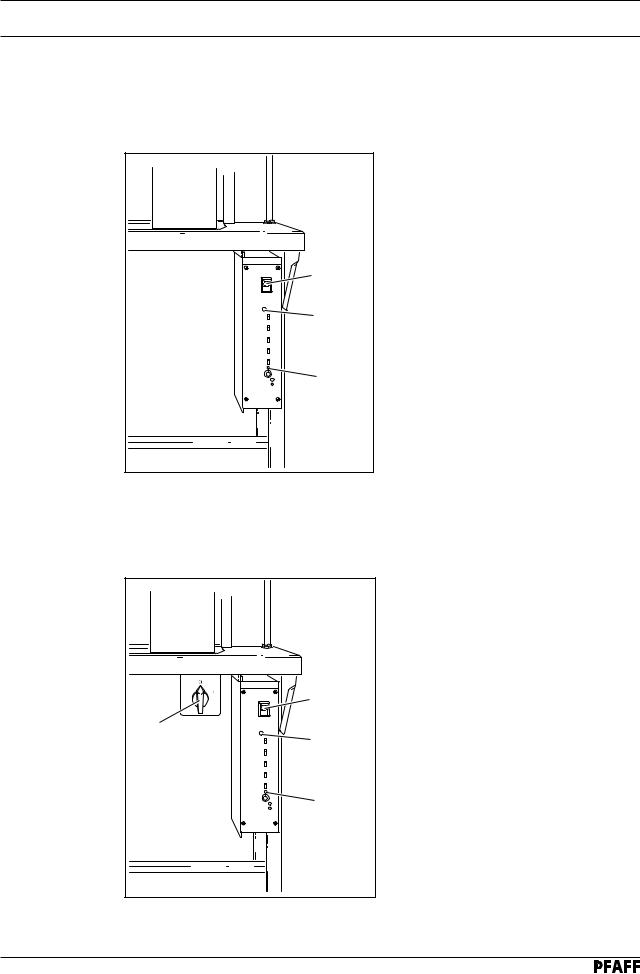
7.01 |
On/off switch on machines with mini-stop motor |
|
|
|
without edge trimmer -725/.. or -726/.. |
|
|
|
● The machine is switched on or off by |
||
|
pressing the on/off switch 1. |
||
|
● The illuminated diode 2 controls the |
||
|
machine operation |
|
|
|
Switch 1 on: |
|
|
|
Diode on |
= |
Machine ready for |
|
1 |
|
operation |
|
|
|
|
|
Diode flashes |
= |
Fault |
|
3 |
|
|
|
Switch 1 off: |
|
|
|
Diode flashes |
= |
Machine still |
|
2 |
|
under electric |
|
|
|
current for about |
|
|
|
4 sec. |
|
Diode out |
= |
Machine off |
● The machine speed can be adjusted on potentiometer3.
7.02 |
On/off switch on machines with mini-stop motor |
|
|
|
|
and edge trimmer -725/.. oder -726/.. |
|
|
|
|
|
● The machine is switched on or off by |
||
|
|
turning the on/off switch 1. |
||
|
|
● The illuminated diode 2 controls the |
||
|
|
machine operation |
|
|
|
|
Switch 3 on: |
|
|
|
3 |
Diode on |
= |
Machine ready for |
|
|
|
operation |
|
|
|
|
|
|
|
1 |
Diode flashes |
= |
Fault |
|
4 |
|
|
|
|
|
Switch 3 off: |
|
|
|
|
Diode flashes |
= |
Machine still |
|
2 |
|
|
under electric |
|
|
|
|
current for about |
|
|
|
|
4 sec. |
|
|
Diode out |
= |
Machine off |
|
Fig. 7 - 02 |
● The machine speed can be adjusted on |
||
|
|
|||
|
|
potentiometer4. |
|
|
7 - 1
Downloaded from www.Manualslib.com manuals search engine
Controls
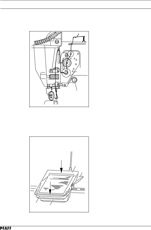
7.03 |
Button on machine head (only on machines with -911/..) |
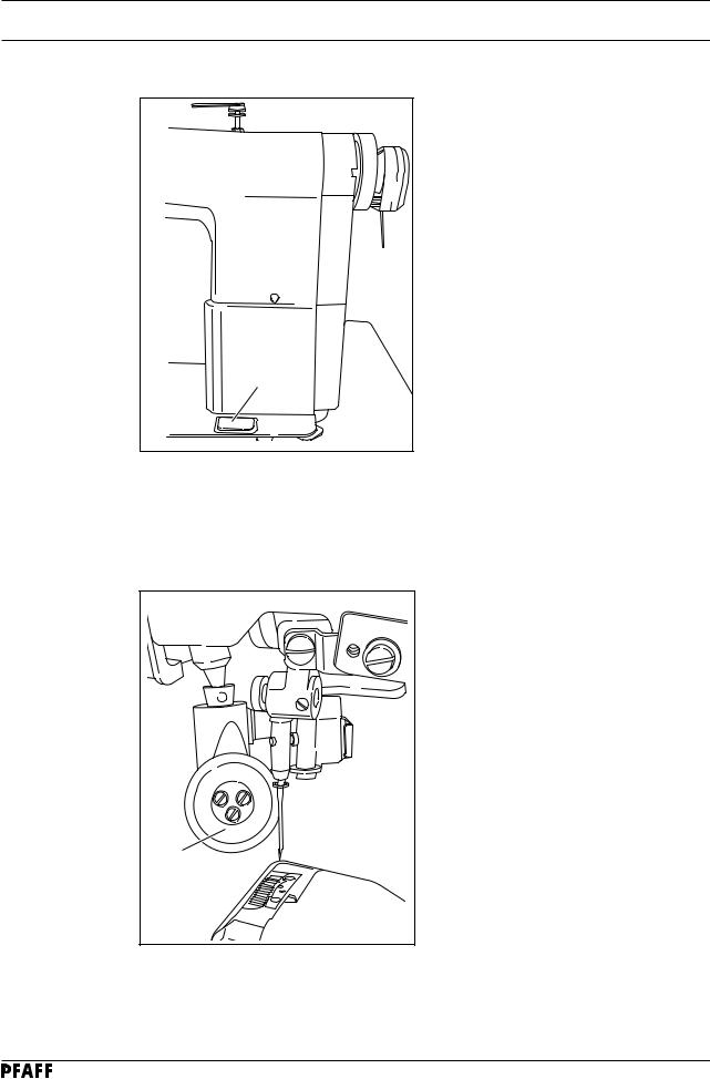
● If button 1 is operated during sewing, the machine switches to reverse sewing.
|
1 |
|
|
|
|
Fig. 7 - 03 |
|
|
|
7.04 |
Pedal |
|
|
|
|
|
0 |
= |
Neutral position |
|
|
1 |
= |
Sewing |
|
|
2 |
= |
Raise roller presser (on |
|
|
|
|
machines with -910/..) |
|
0 |
3 |
= |
Trim sewing threads (on |
|
|
|
machines with -900/..) |
|
|
|
|
|
|
|
|
1 |
|
|
|
2 |
|
|
|
|
3 |
|
|
|
|
Fig. 7 - 04 |
|
|
|
7 - 2
Downloaded from www.Manualslib.com manuals search engine
Controls
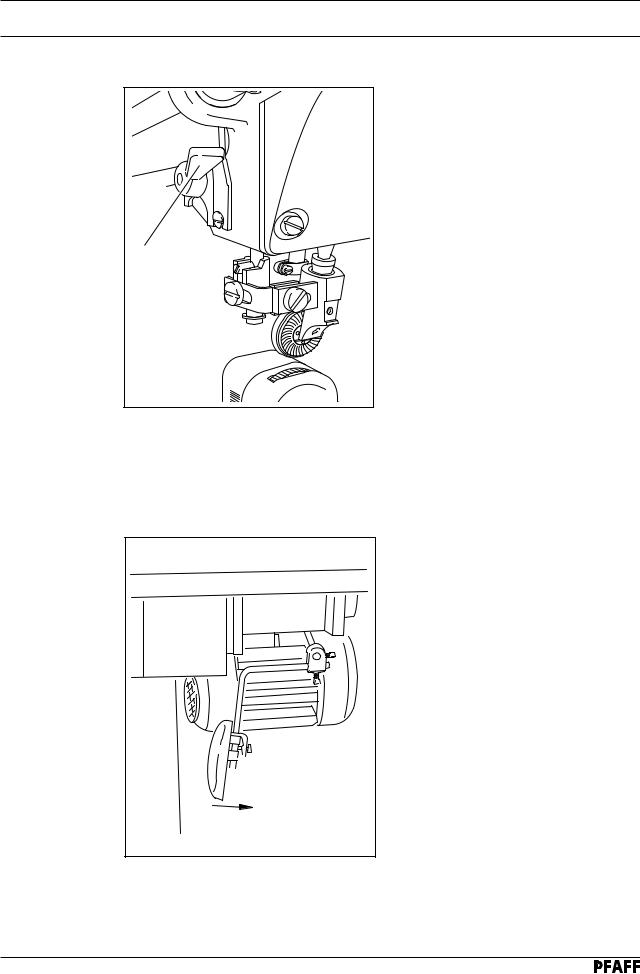
7.05 |
Lever for lifting roller presser |
1 |
Fig. 7 - 05 |
●The roller presser can be raised by turning lever 1.
7.06 |
Knee lever |
● The roller presser can be raised by pressing the knee lever 1 in the direction of the arrow.
 1
1
Fig. 7 - 06
7 - 3
Downloaded from www.Manualslib.com manuals search engine
Controls
7.07 |
Key for setting stitch length |
|
1 |
|
Fig. 7 - 07 |
●The stitch length is set by pressing key 1 and turning the balance wheel (see
Chapter 9.08 Setting the stitch length).
7.08 |
Swing out roller presser |
● When the roller presser is raised, it can be swung out by pulling it lightly downwards.
1
Fig. 7 - 08
7 - 4
Downloaded from www.Manualslib.com manuals search engine
Controls
7.09 |
Edge trimmer -725/04 for 471 |
|
|
|
3 |
|
Keep your hands away from the |
|
2 |
4 |
moving knife! Danger of injury! |
|
|
||
|
|
6 |
Switch on knife drive: |
|
|
5 |
● Move lever 1 backwards. The knife |
|
|
moves into operating position. |
|
|
|
|
|
|
|
|
Switch off knife drive: |
|
|
|
● Press lever 1. The knife swings |
|
|
|
backwards. |
|
|
|
Switch on edge guide: |
|
|
|
● Swing edge guide 2 into position by hand |
|
|
|
and press lever 3. The edge guide 2 |
|
|
|
moves into its operating position. |
|
|
1 |
Switch off edge guide: |
|
|
|
● Raise edge guide 2 and let it click into |
|
Fig. 7 - 09 |
|
position. The edge guide 2 is out of |
|
|
|
|
|
|
|
operation. |
|
|
|
● Raise lever 4. The edge guide swings |
|
|
|
backwards. |
|
Changing the knife: |
|
|
The following work may only be carried out by technical staff or by persons who have been properly instructed.
●Switch off the machine.
●Loosen screw 5 and remove knife 6.
●Insert new knife and slightly tighten screw 5.
●Adjust the knife according to Chaper 11.05.05 Cutting stroke and tighten screw 5.
7 - 5
Downloaded from www.Manualslib.com manuals search engine
Controls
7.10 |
Edge trimmer -725/04 for 474 and 491 |
|
|
|
|
3 |
|
|
|
|
4 |
|
|
|
|
2 |
|
|
|
|
1 |
7 |
6 |
5 |
|
Fig. 7 - 10 |
|
|
|
Keep your hands away from the moving knife! Danger of injury!
Switch on knife drive:
● Move lever 1 backwards. The knife moves into operating position.
Switch off knife drive:
● Press lever 1. The knife swings backwards.
Switch on edge guide:
●Swing edge guide 2 into position by hand and press lever 3. The edge guide 2 moves into its operating position.
Switch off edge guide:
●Raise edge guide 2 and let it click into position. The edge guide 2 is out of operation.
●Raise lever 4. The edge guide swings backwards.
Changing the knife:
The following work may only be carried out by technical staff or by persons who have been properly instructed.
●Switch off the machine.
●Loosen screw 5 and remove knife 6.
●Insert new knife and push it close to needle plate insert 7.
●Slightly tighten screw 5.
●Adjust the knife according to Chaper 11.05.07 Knife position and tighten screw 5.
7 - 6
Downloaded from www.Manualslib.com manuals search engine
Controls
7.11 |
Edge trimmer -726/05 for 491 |
|
|
|
|
|
3 |
|
|
6 |
2 |
|
|
|
1 |
|
7 |
4 |
|
|
|
5 |
|
|
Fig. 7 - 11 |
|
|
Keep your hands away from the moving knife! Danger of injury!
Switch on knife drive:
● By turning lever 1 the knife is moved into its operating position.
Switch off knife drive:
● By pressing lever 2 or key 3 the knife is put out of operation.
Switch on edge guide:
● After lever 4 has been pressed, the edge guide moves into its starting position.
Switch off edge guide:
● By raising lever 5, the edge guide is put out of operation.
Changing the knife:
The following work may only be carried out by technical staff or by persons who have been properly instructed.
●Switch off the machine.
●Loosen screw 6 and remove knife 7.
●Insert new knife and push it close to needle plate insert.
●Tighten screw 6.
●Adjust the knife according to Chapter 11.06.01 Position of the knife to the needle plate and Chapter 11.06.02 Knife crosswise to sewing direction.
7 - 7
Downloaded from www.Manualslib.com manuals search engine
Installation and commissioning
8 |
Installation and commissioning |
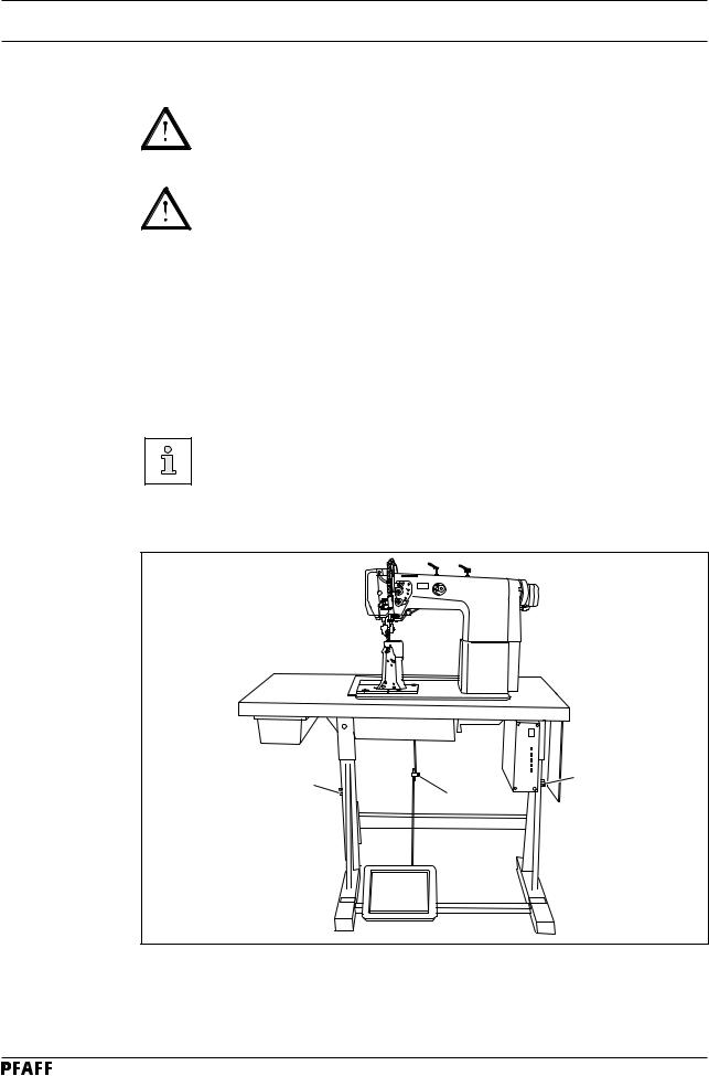
The machine must only be installed and commissioned by qualified personnel!
All relevant safety regulations must be strictly adhered to!
If the machine is delivered without a table, be sure to use a stand and table top that can hold the weight of the machine with its motor.
It is very important to ensure that the stand of the machine is firm and steady, also during sewing.
8.01 Installation
The site where the machine is installed must be provided with suitable connections for electric current.
It must be ensured that the standing surface of the machine site is firm and horizontal, and that sufficient lighting is provided for.
For packing and transportation reasons the table top is in the lowered position.
The table height is adjusted as described below.
8.01.01 Adjusting the table height
1 |
1 |
|
2 |
||
|
Fig. 8 - 01
●Loosen screws 1 and 2 and set the table height as required.
●Firmly tighten screw 1.
●Set the required pedal position and tighten screw 2.
8 - 1
Downloaded from www.Manualslib.com manuals search engine
Installation and commissioning |
|
|
8.01.02 |
Fitting the tilt lock |
|
|
|
Switch off the machine! |
|
|
Danger of injury if the machine |
|
|
is the machine is started |
|
|
accidentally! |
|
2 |
● Screw on the tilt lock 1, provided in the |
|
|
accessories, using screw 2. |
|
|
Do not operate the machine |
|
|
without tilt lock 1. Danger of |
|
|
crushing between sewing head |
|
|
and table top! |
|
1 |
|
|
Fig. 8 - 02 |
|
8.01.03 |
Tensioning the v-belt (does not apply to machines with mini-stop motor) |
|
2 cm |
1 |
2 |
Fig. 8 - 03 |
●Loosen the nuts 1.
●Set tension of v-belt using motor bracket 2.
●Tighten nuts 1.
8 - 2
Downloaded from www.Manualslib.com manuals search engine
Installation and commissioning
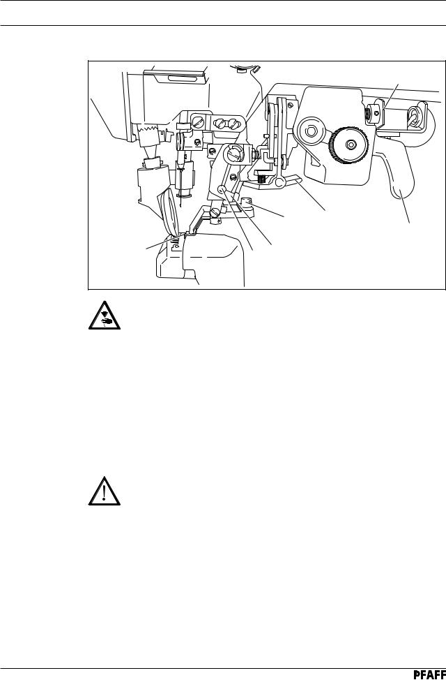
8.01.04 Fitting the top v-belt guard
|
6 |
2 |
7 |
1 |
5 |
3 |
9 |
|
9 |
8 |
|
|
4 |
Fig. 8 - 04 |
|
●Attach belt guard 1 with screws 2 and 3.
●Place spacing sleeve 4 between belt guard 1 and the machine housing.
●Attach belt guard 5 with screws 6 and 7.
●Place spacing sleeve 4 between belt guard 5 and the machine housing.
●Attach belt guard 8 with screws 9.
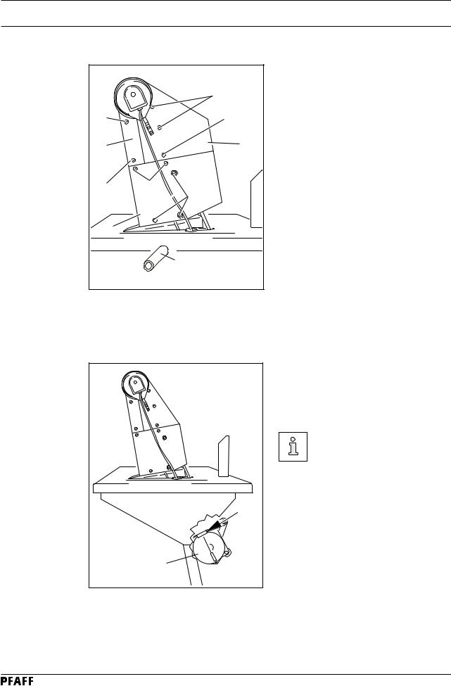
8.01.05 Fitting the bottom v-belt guard (does not apply to machines with mini-stop motor)
● Adjust the v-belt guard 1 so that the motor pulley and v-belt run freely.
● Tighten screws 2. Fig. 8-05 shows a Quick motor.
If another motor is used, the instruction manual of the motor
must be complied with.
2
 2
2
1
Fig. 8 - 05
8 - 3
Downloaded from www.Manualslib.com manuals search engine

Installation and commissioning
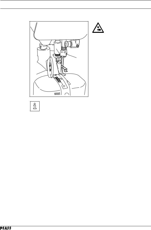
8.01.06 Fitting the synchronizer
4 |
3 |
1 |
2 |
Fig. 8 - 06 |
●Attach position stop 1 using screws 2.
●Push synchronizer 3 onto the shaft so that the position stop 1 is in the groove of the synchronizer (see arrow).
●Slightly tighten screws 4.
●Insert the synchronizer plug in the connection socket of the control box.
●Adjust the synchronizer 3 (see Chapter 11.04.01 Adjusting the Synchronizer).
8.01.07 Fitting the reel stand
Fig. 8 - 07 |
●Fit the reel stand as shown in Fig. 8-07.
●Afterwards insert the stand in the hole in the table top and secure it with the nuts provided.
8 - 4
Downloaded from www.Manualslib.com manuals search engine

Installation and commissioning
8.02 Commissioning
●Check the machine, particularly the electrical wiring, for any damage.
●Clean the machine thoroughly and then oil it or fill in oil (see Chapter 10 Care and maintenance).
●Have a mechanic check whether the motor of the machine can be operated with the available power supply, and that the motor is correctly connected in the junction box. If there are any discrepancies the machine must not be operated under any circumstances.
|
The machine may only be connected to an earthed socket! |
|
● When the machine is running, the balance wheel must turn towards the operator. If it does |
|
not, have the motor connection changed by a mechanic. |
|
● Machines with pneumatic equipment must be connected to the compressed air supply. |
|
The pressure gauge should indicate a pressure of 6 bar. If necessary, adjust to the correct |
|
setting (see Chapter 10.05 Checking adjusting the air pressure). |
8.03 |
Switching the machine on/off |
|
● Switch the machine on or off (see Chapter 7.01 On/off switch). |
8 - 5
Downloaded from www.Manualslib.com manuals search engine

Setting up
9 |
Setting up |
All instructions and regulations in this instruction manual must be observed.
Special attention must be paid to all safety regulations!
All setting-up work must only be carried out by personnel with the appropriate training. For all setting-up work the machine must be disconnected from its power supply by turning off the on/off switch, or removing the plug from the electric power socket.
9.01 |
Inserting the needle on model 471 and 491 |
||
|
|
|
Switch the machine off! |
|
|
|
Danger of injury if the machine |
|
|
|
is started accidentally! |
|
|
|
Only use needles of system 134. |
|
|
|
● Raise the roller presser 1 and swing it |
|
|
|
out. |
|
|
|
● Loosen screw 2 and insert the needle as |
|
|
|
far as possible. The long groove must |
|
|
2 |
face to the right on model 471 and to the |
|
|
left on model 491. |
|
|
|
|
|
|
|
|
● Tighten screw 2 and swing roller presser 1 |
|
1 |
|
back into position. |
|
|
|
|
|
|
|
Fig. 9-01 shows model 491. |
|
Fig. 9 - 01 |
|
|
|
|
The choice of needle depends on the model of the machine and the thread and |
|
|
|
material used (see Chapter 3.02 Needles and threads). |
|
9 - 1
Downloaded from www.Manualslib.com manuals search engine
Setting up
9.02 |
Inserting the needle on model 474 |
|
|
|
Switch the machine off! |
|
|
Danger of injury if the machine |
|
|
is started accidentally! |
|
|
Only use needles of system 134-35. |
|
2 |
● Raise the roller presser 1 and swing it |
|
|
out. |
|
2 |
● Loosen screws 2 and insert the needles |
|
so that the long groove of the left needle |
|
|
|
|
|
|
is facing right, and that of the right needle |
|
|
is facing left. |
|
1 |
● Tighten screws 2 and swing roller |
|
|
presser 1 back into position. |
|
Fig. 9 - 02 |
|
The choice of needle depends on the model of the machine and the thread and material used (see Chapter 3.02 Needles and threads).
9 - 2
Downloaded from www.Manualslib.com manuals search engine
Setting up
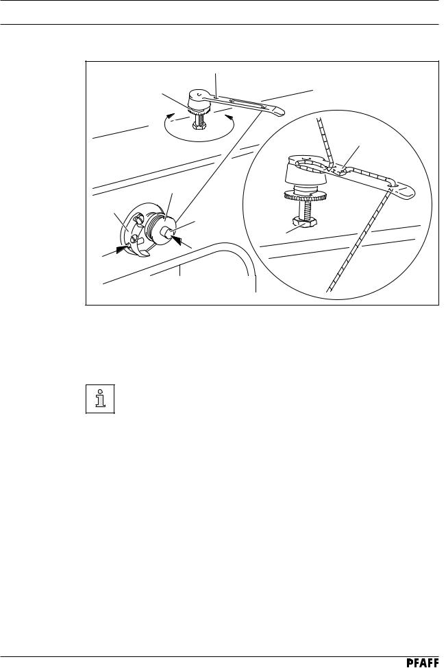
9.03 |
Winding the bobbin thread; adjusting the primary thread tension |
|
|
4 |
|
|
_ |
+ |
|
|
|
|
|
6 |
|
|
1 |
|
3 |
2 |
|
|
|
|
|
5 |
|
Fig. 9 - 03 |
|
|
● Place an empty bobbin 1 onto bobbin winder spindle 2. |
|
|
● Thread the bobbin as shown in Fig. 9 - 03 and wind it clockwise around bobbin 1 a few |
|
|
times. |
|
|
● Switch on the bobbin winder while at the same time pressing bobbin winder spindle 2 and |
|
|
lever 3. |
|
The bobbin is filled up during sewing.
●The thread tension on bobbin 1 can be adjusted using knurled screw 4.
●The bobbin winder stops automatically when bobbin 1 is full.
If the thread is wound unevenly:
●Loosen nut 5.
●Turn thread guide 6 accordingly.
●Tighten nut 5.
9 - 3
Downloaded from www.Manualslib.com manuals search engine
 Loading...