


481
483
Service manual
296-12-17 437 Justieranleitung engl. 1.97
Contents |
|
|
|
|
Page |
|
Checking and adjustment aid ..................................................................................... |
3 |
1 |
Preliminary adjustment of the needle height ............................................................. |
4 |
2 |
Zeroing the feed motion ......................................................................................... |
5-6 |
3 |
Zeroing the needle feed motion (not applicable to PFAFF 483) ................................. |
7 |
4 |
Feed lifting motion ..................................................................................................... |
8 |
5 |
Feed dog height ......................................................................................................... |
9 |
6 |
Feed driving motion ................................................................................................. |
10 |
7 |
Timing the needle feed motion (not applicable to PFAFF 483) ................................. |
11 |
8 |
Centering the needle in the needle hole ............................................................. |
12-13 |
9 |
Eccentric hook shaft bearing and hook-to-needle clearance .................................... |
14 |
10 |
Needle rise, final adjustment of needle height and bobbin case positioning finger . 15 |
|
11 |
Vertical position of bobbin case opener ................................................................... |
16 |
12 |
Position of bobbin case opener ................................................................................ |
17 |
13 |
Timing the bobbin case opener ................................................................................ |
18 |
14 |
Clearance between presser foot and needle plate................................................... |
19 |
15 |
Eliminating feed differences (not applicable to PFAFF 483) ..................................... |
20 |
16 |
Tension release mechanism .................................................................................... |
21 |
17 |
Thread check spring and thread regulator ................................................................ |
22 |
18 |
Knee lever resting position ...................................................................................... |
23 |
19 |
Knee lever play......................................................................................................... |
24 |
20 |
Adjusting the knee lever motion .............................................................................. |
25 |
21 |
Bobbin winder .......................................................................................................... |
26 |
22 |
Limiting the stitch length ......................................................................................... |
27 |
23 |
Matching forwards and reverse stitch lengths......................................................... |
28 |
24 |
Presser foot pressure .............................................................................................. |
29 |
|
|
PFAFF 2 |
Notes on safety
●The machine must only be operated in full knowledge of the instruction book and by persons with appropriate training.
●Before commissioning the machine also read the motor manufacturer’s safety notes and instruction manual.
●The machine must only be used for the purpose intended. It must not be operated without the safety devices it is equipped with; all valid safety regulations must be adhered to.
●When gauge parts are exchanged (e.g. needle, presser foot, needle plate, feed dog and bobbin), during threading, when the workplace is left, and during service work, the machine must be isolated from the mains by switching off the main switch or disconnecting the mains plug.
●On mechanically operated clutch motors without start inhibitor it is necessary to wait until the motor has stopped.
●Daily servicing work must only be carried out by persons with appropriate training.
●Repairs and special maintenance work must only be carried out by trained technicians or persons with appropriate training.
●For service or repair work on pneumatic systems the machine must be disconnected from the compressed air supply system. The only exceptions to this are adjustments and function checks carried out by appropriately trained technicians.
●Work on the electrical equipment must only be carried out by electrical engineers or other appropriately trained technicians.
●It is not permitted to work on live parts. For exceptions please see the EN 50 110 regulations.
●Conversions or changes to the machine must only be made on adherence to all safety regulations.
●For repairs, only replacement parts approved by us must be used.
●The sewing head must not be operated until it is ascertained that the whole sewing unit corresponds to EC-regulations.
Tools, gauges and other adjustment aids
●1 set of screwdrivers with blades from 2 to 10 mm wide
●1 set of spanners from 7 to 14 mm wide
●1 set of hexagonal allen keys ranging from 1.5 to 6 mm
●1 wrench, 22 mm wide
●1 metal ruler (part No. 08-880 218-00)
●1 cylindrical pin (5 mm in diameter), part No. 13-030 341-05
●1 adjustment gauge, part No. 61-111 642-19
Notes on the service manual
All the adjustments in this service manual apply for a completely mounted machine. No mention is made of the machine covers that occasionally have to be screwed off and back on for testing and adjustment purposes.
The screws and nuts in brackets ( ) are for the attachment of machine parts that must be loosened before the adjustments and tightened up again afterwards.
Abbreviations
t.d.c = top dead center
b.d.c. = bottom dead center
3 PFAFF
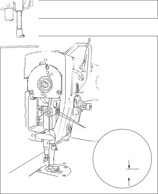
Checking and adjustment aid
By inserting the cylindrical pin in one of the adjustment holes 1 to 6 it is possible to fix the required needle bar positions very precisely.
Turn the handwheel until the needle bar is roughly in the required position.
Insert the 5 mm thick cylindrical pin in the specified adjustment hole and press against it.
Turn the handwheel slightly to and fro until the cylindrical pin engages in the crank recess behind the bearing plate, thus blocking the machine.
3
 6
6

 4
4
1
 5
5
Adjustment hole 1 = 0.6 mm past top dead center of the needle bar (0.6 past t.d.c.).
Adjustment hole 3 = 0.6 mm past the bottom dead center of the needle bar (0.6 past b.d.c).
Adjustment hole 4 = 1.8 mm past the bottom dead center of the needle bar (needle rise position).
Adjustment hole 5 = top dead center of the needle bar (t.d.c. N).
Adjustment hole 6 = 4 mm past bottom dead center of needle bar (4 past b.d.c).
PFAFF 3
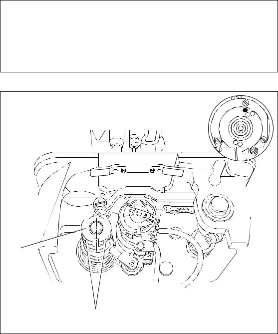
1 |
Preliminary adjustment of needle height |
Requirement
With the needle bar at b.d.c. there must be a clearance of 16.5 mm between needle holder
and needle plate.
2
 1
1
16,5 mm
●Move needle bar 1 (screw 2) according to the requirement. Make sure that, when looking in the feed direction, the needle retaining screw points to the right.
4 PFAFF

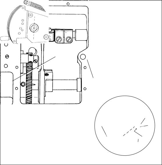
2 |
Zeroing the feed motion |
Requirement
The feed dog must not move when turning the handwheel with the stitch length set at “0”.
2.1Zeroing procedure with the gearbox closed
6 |
8 |
7 8 mm |
5
2
1 |
3 |
4
●Raise the presser foot and set the stitch length control lever 1 at its lowest position.
●Turn eccentric bushing 2 (screw 3) so that mark 4 is roughly at the bottom and the edge of the milled surface is at an angle of 45° to the machine front (for final adjustment see section 23).
●nsert an allen key in one of the holes in collar 5. Use the allen key to hold the shaft in position.
●Rotate the handwheel and at the same time turn shaft 6 (screw 7) with the allen key according to the requirement. Remember that in the PFAFF 483 there must be a clearance of 8 mm between the bearing bush and actuating crank 8.
PFAFF 5
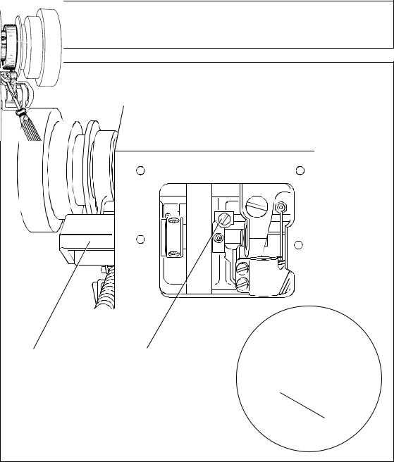
2.2Zeroing procedure with the gearbox open
5 |
6 |
|
2
1 |
3 |
|
|
|
4 |
●Raise the presser foot and set the stitch length control lever 1 at its lowest position.
●Turn eccentric bushing 2 (screw 3) so that mark 4 is roughly at the bottom and the edge of the milled surface is at an angle of 45° to the machine front (for final adjustment see section 23).
●Turn crank 5 (screw 6) according to the requirement.
6 PFAFF
3 |
Zeroing the needle feed motion (Adjustment not applicable to Pfaff 483) |
Requirement:
With the stitch length control set at “0” the needle bar should make no feed motion when
the handwheel is turned.
1 |
2 |
|
3 |
●Adjust needle feed regulating crank 1 (screw 2) according to the requirement.
Adjustment aid:
Insert a screwdriver in needle feed driving crank 3 - it must remain still when the handwheel is turned.
PFAFF 7
4 |
Feed lifting motion |
Requirement
With the stitch length set at “0”
the feed dog should be at t.d.c. when the needle bar is at a position 0.6 mm past b.d.c (cylindrical pin in hole “3”; for PFAFF 481)
or 0.6 mm past t.d.c (cylindrical pin in hole “1”; for PFAFF 483).
In this position, the notch in feed lifting eccentric 1 should be positioned perpendicularly below the center of the shaft.
3 |
1 |
2 |
● Turn feed lifting eccentric 1 (screws 2) according to the requirement.
8 PFAFF

5 |
Feed dog height |
Requirement
With the stitch length set at “0” and the needle bar at a position 0.6 mm past b.d.c (cylindrical pin in hole “3”, for PFAFF 481) and 0.6 past t.d.c. (cylindrical pin in hole “1”; for PFAFF 483)
1.the feed dog must be positioned in the middle of the needle plate slots when looked at from the side as well as in feeding direction.
2.the feed dog must be at its top point of reversal and must contact the gauge throughout its entire length.
3 |
1 |
1 |
3 |
5 |
4 |
6 |
2 |
●Move feed bar 1 (screw 2) according to requirement 1.
●Lower the presser foot until it rests on the gauge.
●Turn eccentric 3 (screw 4) and eccentric 5 (screw 6) according to requirement 2.
PFAFF 9
 Loading...