


 Loading...
Cat. No. W238-E1-10
SYSMAC
CQM1H/CQM1 Series
Dedicated I/O Units
OPERATION MANUAL
CQM1H/CQM1Series
Dedicated I/O Units
Operation Manual
Revised November 2003
iv
Notice:
OMRON products are manufactured for use according to proper procedures by a qualified operator and only for the purposes described in this manual.
The following conventions are used to indicate and classify precautions in this manual. Always heed the information provided with them. Failure to heed precautions can result in injury to people or damage to property.
!DANGER Indicates an imminently hazardous situation which, if not avoided, will result in death or serious injury.
!WARNING Indicates a potentially hazardous situation which, if not avoided, could result in death or serious injury.
!Caution Indicates a potentially hazardous situation which, if not avoided, may result in minor or moderate injury, or property damage.
OMRON Product References
All OMRON products are capitalized in this manual. The word “Unit” is also capitalized when it refers to an OMRON product, regardless of whether or not it appears in the proper name of the product.
The abbreviation “Ch,” which appears in some displays and on some OMRON products, often means “word” and is abbreviated “Wd” in documentation in this sense.
The abbreviation “PC" means Programmable Controller and is not used as an abbreviation for anything else.
Visual Aids
The following headings appear in the left column of the manual to help you locate different types of information.
Note Indicates information of particular interest for efficient and convenient operation of the product.
1,2,3... 1. Indicates lists of one sort or another, such as procedures, checklists, etc.
OMRON, 1993
All rights reserved. No part of this publication may be reproduced, stored in a retrieval system, or transmitted, in any form, or by any means, mechanical, electronic, photocopying, recording, or otherwise, without the prior written permission of OMRON.
No patent liability is assumed with respect to the use of the information contained herein. Moreover, because OMRON is constantly striving to improve its high-quality products, the information contained in this manual is subject to change without notice. Every precaution has been taken in the preparation of this manual. Nevertheless, OMRON assumes no responsibility for errors or omissions. Neither is any liability assumed for damages resulting from the use of the information contained in this publication.
v
vi
TABLE OF CONTENTS
PRECAUTIONS . . . . . . . . . . . . . . . . . . . . . . . . . . . . . . . . |
xv |
|
1 |
Intended Audience . . . . . . . . . . . . . . . . . . . . . . . . . . . . . . . . . . . . . . . . . . . . . . . . . |
xvi |
2 |
General Precautions . . . . . . . . . . . . . . . . . . . . . . . . . . . . . . . . . . . . . . . . . . . . . . . . |
xvi |
3 |
Safety Precautions. . . . . . . . . . . . . . . . . . . . . . . . . . . . . . . . . . . . . . . . . . . . . . . . . . |
xvi |
4 |
Operating Environment Precautions . . . . . . . . . . . . . . . . . . . . . . . . . . . . . . . . . . . . |
xvii |
5 |
Application Precautions . . . . . . . . . . . . . . . . . . . . . . . . . . . . . . . . . . . . . . . . . . . . . |
xviii |
PART I |
|
|
B7A Interface Unit . . . . . . . . . . . . . . . . . . . . . . . . . . . . . . |
1 |
|
SECTION 1 |
|
|
Features and System Configuration . . . . . . . . . . . . . . . . |
3 |
|
1-1 |
Features . . . . . . . . . . . . . . . . . . . . . . . . . . . . . . . . . . . . . . . . . . . . . . . . . . . . . . . . . . |
4 |
1-2 |
System Configuration . . . . . . . . . . . . . . . . . . . . . . . . . . . . . . . . . . . . . . . . . . . . . . . |
5 |
1-3 |
Connecting Devices . . . . . . . . . . . . . . . . . . . . . . . . . . . . . . . . . . . . . . . . . . . . . . . . |
5 |
1-4 |
Word Allocation . . . . . . . . . . . . . . . . . . . . . . . . . . . . . . . . . . . . . . . . . . . . . . . . . . . |
6 |
1-5 |
Bit Allocation . . . . . . . . . . . . . . . . . . . . . . . . . . . . . . . . . . . . . . . . . . . . . . . . . . . . . |
7 |
SECTION 2 |
|
|
Nomenclature and Settings . . . . . . . . . . . . . . . . . . . . . . . |
11 |
|
2-1 |
Nomenclature . . . . . . . . . . . . . . . . . . . . . . . . . . . . . . . . . . . . . . . . . . . . . . . . . . . . . |
12 |
2-2 |
Switch Settings . . . . . . . . . . . . . . . . . . . . . . . . . . . . . . . . . . . . . . . . . . . . . . . . . . . . |
17 |
SECTION 3 |
|
|
Connections . . . . . . . . . . . . . . . . . . . . . . . . . . . . . . . . . . . . |
19 |
|
3-1 |
Connections to B7A Link Terminals. . . . . . . . . . . . . . . . . . . . . . . . . . . . . . . . . . . . |
20 |
3-2 |
Wiring . . . . . . . . . . . . . . . . . . . . . . . . . . . . . . . . . . . . . . . . . . . . . . . . . . . . . . . . . . . |
22 |
Appendices |
|
|
A |
Specifications . . . . . . . . . . . . . . . . . . . . . . . . . . . . . . . . . . . . . . . . . . . . . . . . . . . . . |
25 |
PART II |
|
|
G730 Interface Unit . . . . . . . . . . . . . . . . . . . . . . . . . . . . . |
27 |
|
SECTION 1 |
|
|
Features and System Configuration . . . . . . . . . . . . . . . . |
29 |
|
1-1 |
Features . . . . . . . . . . . . . . . . . . . . . . . . . . . . . . . . . . . . . . . . . . . . . . . . . . . . . . . . . . |
30 |
1-2 |
System Configuration . . . . . . . . . . . . . . . . . . . . . . . . . . . . . . . . . . . . . . . . . . . . . . . |
31 |
1-3 |
Connecting Devices . . . . . . . . . . . . . . . . . . . . . . . . . . . . . . . . . . . . . . . . . . . . . . . . |
34 |
SECTION 2 |
|
|
Nomenclature and Settings . . . . . . . . . . . . . . . . . . . . . . . |
35 |
|
2-1 |
Nomenclature . . . . . . . . . . . . . . . . . . . . . . . . . . . . . . . . . . . . . . . . . . . . . . . . . . . . . |
36 |
2-2 |
Switch Settings . . . . . . . . . . . . . . . . . . . . . . . . . . . . . . . . . . . . . . . . . . . . . . . . . . . . |
39 |
SECTION 3 |
|
|
Connections . . . . . . . . . . . . . . . . . . . . . . . . . . . . . . . . . . . . |
43 |
|
3-1 |
Transmission Cables . . . . . . . . . . . . . . . . . . . . . . . . . . . . . . . . . . . . . . . . . . . . . . . . |
44 |
3-2 |
External Output Connection Cables . . . . . . . . . . . . . . . . . . . . . . . . . . . . . . . . . . . . |
45 |
SECTION 4 |
|
|
Operation . . . . . . . . . . . . . . . . . . . . . . . . . . . . . . . . . . . . . . |
47 |
|
4-1 |
Word Allocation . . . . . . . . . . . . . . . . . . . . . . . . . . . . . . . . . . . . . . . . . . . . . . . . . . . |
48 |
4-2 |
Handling Power On. . . . . . . . . . . . . . . . . . . . . . . . . . . . . . . . . . . . . . . . . . . . . . . . . |
54 |
4-3 |
Transmission Delay Time . . . . . . . . . . . . . . . . . . . . . . . . . . . . . . . . . . . . . . . . . . . . |
54 |
vii
|
TABLE OF CONTENTS |
|
Appendices |
|
|
A |
Specifications . . . . . . . . . . . . . . . . . . . . . . . . . . . . . . . . . . . . . . . . . . . . . . . . . . . . |
57 |
B |
Troubleshooting . . . . . . . . . . . . . . . . . . . . . . . . . . . . . . . . . . . . . . . . . . . . . . . . . . |
59 |
PART III |
|
|
I/O Link Unit . . . . . . . . . . . . . . . . . . . . . . . . . . . . . . . . . . . |
63 |
|
SECTION 1 |
|
|
Features and System Configuration . . . . . . . . . . . . . . . . |
65 |
|
1-1 |
Features . . . . . . . . . . . . . . . . . . . . . . . . . . . . . . . . . . . . . . . . . . . . . . . . . . . . . . . . . |
66 |
1-2 |
System Configuration . . . . . . . . . . . . . . . . . . . . . . . . . . . . . . . . . . . . . . . . . . . . . . |
66 |
1-3 |
Connecting Devices . . . . . . . . . . . . . . . . . . . . . . . . . . . . . . . . . . . . . . . . . . . . . . . . |
66 |
1-4 |
Word Allocation. . . . . . . . . . . . . . . . . . . . . . . . . . . . . . . . . . . . . . . . . . . . . . . . . . . |
67 |
SECTION 2 |
|
|
Nomenclature and Settings. . . . . . . . . . . . . . . . . . . . . . . . |
69 |
|
2-1 |
Nomenclature. . . . . . . . . . . . . . . . . . . . . . . . . . . . . . . . . . . . . . . . . . . . . . . . . . . . . |
70 |
2-2 |
Switch Settings . . . . . . . . . . . . . . . . . . . . . . . . . . . . . . . . . . . . . . . . . . . . . . . . . . . |
71 |
SECTION 3 |
|
|
Connections . . . . . . . . . . . . . . . . . . . . . . . . . . . . . . . . . . . . |
73 |
|
3-1 |
SYSMAC BUS Cable Connections . . . . . . . . . . . . . . . . . . . . . . . . . . . . . . . . . . . . |
74 |
Appendices |
|
|
A |
Specifications . . . . . . . . . . . . . . . . . . . . . . . . . . . . . . . . . . . . . . . . . . . . . . . . . . . . |
77 |
PART IV |
|
|
Analog Input Unit and Analog Power Supply Units . . . |
79 |
|
SECTION 1 |
|
|
Features and System Configuration . . . . . . . . . . . . . . . . |
81 |
|
1-1 |
Features . . . . . . . . . . . . . . . . . . . . . . . . . . . . . . . . . . . . . . . . . . . . . . . . . . . . . . . . . |
82 |
1-2 |
System Configuration . . . . . . . . . . . . . . . . . . . . . . . . . . . . . . . . . . . . . . . . . . . . . . |
83 |
1-3 |
Connecting Devices . . . . . . . . . . . . . . . . . . . . . . . . . . . . . . . . . . . . . . . . . . . . . . . . |
83 |
1-4 |
System Construction . . . . . . . . . . . . . . . . . . . . . . . . . . . . . . . . . . . . . . . . . . . . . . . |
84 |
SECTION 2 |
|
|
Nomenclature and Functions . . . . . . . . . . . . . . . . . . . . . . |
85 |
|
2-1 |
Nomenclature. . . . . . . . . . . . . . . . . . . . . . . . . . . . . . . . . . . . . . . . . . . . . . . . . . . . . |
86 |
2-2 |
Functions . . . . . . . . . . . . . . . . . . . . . . . . . . . . . . . . . . . . . . . . . . . . . . . . . . . . . . . . |
89 |
SECTION 3 |
|
|
Operation . . . . . . . . . . . . . . . . . . . . . . . . . . . . . . . . . . . . . . |
91 |
|
3-1 |
Settings . . . . . . . . . . . . . . . . . . . . . . . . . . . . . . . . . . . . . . . . . . . . . . . . . . . . . . . . . |
92 |
3-2 |
Bit Number Allocation . . . . . . . . . . . . . . . . . . . . . . . . . . . . . . . . . . . . . . . . . . . . . |
94 |
3-3 |
Programming and Adjustment . . . . . . . . . . . . . . . . . . . . . . . . . . . . . . . . . . . . . . . . |
96 |
Appendices |
|
|
A |
Specifications . . . . . . . . . . . . . . . . . . . . . . . . . . . . . . . . . . . . . . . . . . . . . . . . . . . . |
103 |
B |
Troubleshooting . . . . . . . . . . . . . . . . . . . . . . . . . . . . . . . . . . . . . . . . . . . . . . . . . . |
107 |
viii
TABLE OF CONTENTS
PART V
Analog Output Unit and Analog Power Supply Units. . 109
SECTION 1 |
|
|
Features and System Configuration . . . . . . . . . . . . . . . . |
111 |
|
1-1 |
Features of Analog Output Unit . . . . . . . . . . . . . . . . . . . . . . . . . . . . . . . . . . . . . . . |
112 |
1-2 |
System Configuration . . . . . . . . . . . . . . . . . . . . . . . . . . . . . . . . . . . . . . . . . . . . . . . |
112 |
SECTION 2 |
|
|
Nomenclature and Functions . . . . . . . . . . . . . . . . . . . . . . |
115 |
|
2-1 |
Nomenclature . . . . . . . . . . . . . . . . . . . . . . . . . . . . . . . . . . . . . . . . . . . . . . . . . . . . . |
116 |
2-2 |
Functions . . . . . . . . . . . . . . . . . . . . . . . . . . . . . . . . . . . . . . . . . . . . . . . . . . . . . . . . . |
117 |
SECTION 3 |
|
|
Operation . . . . . . . . . . . . . . . . . . . . . . . . . . . . . . . . . . . . . . |
119 |
|
3-1 |
Settings . . . . . . . . . . . . . . . . . . . . . . . . . . . . . . . . . . . . . . . . . . . . . . . . . . . . . . . . . . |
120 |
3-2 |
Bit Number Allocation . . . . . . . . . . . . . . . . . . . . . . . . . . . . . . . . . . . . . . . . . . . . . . |
122 |
3-3 |
Programming and Adjustment . . . . . . . . . . . . . . . . . . . . . . . . . . . . . . . . . . . . . . . . |
123 |
Appendices |
|
|
A |
Specifications . . . . . . . . . . . . . . . . . . . . . . . . . . . . . . . . . . . . . . . . . . . . . . . . . . . . . |
127 |
B |
Troubleshooting . . . . . . . . . . . . . . . . . . . . . . . . . . . . . . . . . . . . . . . . . . . . . . . . . . . |
129 |
PART VI |
|
|
Sensor Unit. . . . . . . . . . . . . . . . . . . . . . . . . . . . . . . . . . . . . |
131 |
|
SECTION 1 |
|
|
Features and System Configuration . . . . . . . . . . . . . . . . |
133 |
|
1-1 |
Features . . . . . . . . . . . . . . . . . . . . . . . . . . . . . . . . . . . . . . . . . . . . . . . . . . . . . . . . . . |
134 |
1-2 |
System Configuration . . . . . . . . . . . . . . . . . . . . . . . . . . . . . . . . . . . . . . . . . . . . . . . |
134 |
1-3 |
Connecting Devices . . . . . . . . . . . . . . . . . . . . . . . . . . . . . . . . . . . . . . . . . . . . . . . . |
135 |
1-4 |
System Construction . . . . . . . . . . . . . . . . . . . . . . . . . . . . . . . . . . . . . . . . . . . . . . . . |
136 |
SECTION 2 |
|
|
Nomenclature and Functions . . . . . . . . . . . . . . . . . . . . . . |
137 |
|
2-1 |
Nomenclature . . . . . . . . . . . . . . . . . . . . . . . . . . . . . . . . . . . . . . . . . . . . . . . . . . . . . |
138 |
2-2 |
Switch Settings . . . . . . . . . . . . . . . . . . . . . . . . . . . . . . . . . . . . . . . . . . . . . . . . . . . . |
142 |
SECTION 3 |
|
|
Connections . . . . . . . . . . . . . . . . . . . . . . . . . . . . . . . . . . . . |
145 |
|
3-1 |
Wiring Precaution . . . . . . . . . . . . . . . . . . . . . . . . . . . . . . . . . . . . . . . . . . . . . . . . . . |
146 |
3-2 |
Mounting and Dismounting the Sensor Module . . . . . . . . . . . . . . . . . . . . . . . . . . . |
148 |
3-3 |
Connection of CQM1-TU001 Remote Console . . . . . . . . . . . . . . . . . . . . . . . . . . . |
149 |
3-4 |
Connection of a Variety of Sensors. . . . . . . . . . . . . . . . . . . . . . . . . . . . . . . . . . . . . |
149 |
SECTION 4 |
|
|
Sensor Module Operation . . . . . . . . . . . . . . . . . . . . . . . . |
153 |
|
4-1 |
Operation without CQM1-TU001 Remote Console . . . . . . . . . . . . . . . . . . . . . . . . |
154 |
SECTION 5 |
|
|
Remote Console Operation . . . . . . . . . . . . . . . . . . . . . . . |
161 |
|
5-1 |
Mode Setting . . . . . . . . . . . . . . . . . . . . . . . . . . . . . . . . . . . . . . . . . . . . . . . . . . . . . . |
162 |
5-2 |
Sensitivity Adjustment . . . . . . . . . . . . . . . . . . . . . . . . . . . . . . . . . . . . . . . . . . . . . . |
162 |
Appendices |
|
|
A |
Specifications . . . . . . . . . . . . . . . . . . . . . . . . . . . . . . . . . . . . . . . . . . . . . . . . . . . . . |
165 |
ix
TABLE OF CONTENTS
PART VII |
|
|
Linear Sensor Interface Units . . . . . . . . . . . . . . . . . . . . . |
175 |
|
SECTION 1 |
|
|
Features and System Configuration . . . . . . . . . . . . . . . . |
177 |
|
1-1 |
Features . . . . . . . . . . . . . . . . . . . . . . . . . . . . . . . . . . . . . . . . . . . . . . . . . . . . . . . . . |
178 |
1-2 |
System Configuration . . . . . . . . . . . . . . . . . . . . . . . . . . . . . . . . . . . . . . . . . . . . . . |
179 |
SECTION 2 |
|
|
Functions . . . . . . . . . . . . . . . . . . . . . . . . . . . . . . . . . . . . . . |
181 |
|
2-1 |
Scaling . . . . . . . . . . . . . . . . . . . . . . . . . . . . . . . . . . . . . . . . . . . . . . . . . . . . . . . . . . |
182 |
2-2 |
Timing Hold. . . . . . . . . . . . . . . . . . . . . . . . . . . . . . . . . . . . . . . . . . . . . . . . . . . . . . |
183 |
2-3 |
Scaled Conversion Data/Comparison Result . . . . . . . . . . . . . . . . . . . . . . . . . . . . . |
186 |
2-4 |
Teaching. . . . . . . . . . . . . . . . . . . . . . . . . . . . . . . . . . . . . . . . . . . . . . . . . . . . . . . . . |
187 |
2-5 |
Forced Zero (Zero-shift) . . . . . . . . . . . . . . . . . . . . . . . . . . . . . . . . . . . . . . . . . . . . |
188 |
2-6 |
Voltage Monitor Output . . . . . . . . . . . . . . . . . . . . . . . . . . . . . . . . . . . . . . . . . . . . . |
188 |
SECTION 3 |
|
|
Nomenclature and Functions . . . . . . . . . . . . . . . . . . . . . . |
191 |
|
3-1 |
Nomenclature. . . . . . . . . . . . . . . . . . . . . . . . . . . . . . . . . . . . . . . . . . . . . . . . . . . . . |
192 |
3-2 |
Terminals . . . . . . . . . . . . . . . . . . . . . . . . . . . . . . . . . . . . . . . . . . . . . . . . . . . . . . . . |
193 |
SECTION 4 |
|
|
Connections . . . . . . . . . . . . . . . . . . . . . . . . . . . . . . . . . . . . |
195 |
|
4-1 |
Mounting and Wiring. . . . . . . . . . . . . . . . . . . . . . . . . . . . . . . . . . . . . . . . . . . . . . . |
196 |
SECTION 5 |
|
|
Basic Operation . . . . . . . . . . . . . . . . . . . . . . . . . . . . . . . . . |
197 |
|
5-1 |
Operating Method . . . . . . . . . . . . . . . . . . . . . . . . . . . . . . . . . . . . . . . . . . . . . . . . . |
198 |
5-2 |
Programming Console Operation . . . . . . . . . . . . . . . . . . . . . . . . . . . . . . . . . . . . . |
199 |
5-3 |
Operation Mode . . . . . . . . . . . . . . . . . . . . . . . . . . . . . . . . . . . . . . . . . . . . . . . . . . . |
200 |
5-4 |
Scaling . . . . . . . . . . . . . . . . . . . . . . . . . . . . . . . . . . . . . . . . . . . . . . . . . . . . . . . . . . |
202 |
5-5 |
Comparison . . . . . . . . . . . . . . . . . . . . . . . . . . . . . . . . . . . . . . . . . . . . . . . . . . . . . . |
205 |
5-6 |
Monitoring . . . . . . . . . . . . . . . . . . . . . . . . . . . . . . . . . . . . . . . . . . . . . . . . . . . . . . . |
207 |
SECTION 6 |
|
|
Applied Operation . . . . . . . . . . . . . . . . . . . . . . . . . . . . . . . |
209 |
|
6-1 |
Scaling Value Teaching . . . . . . . . . . . . . . . . . . . . . . . . . . . . . . . . . . . . . . . . . . . . . |
210 |
6-2 |
Set Value Teaching . . . . . . . . . . . . . . . . . . . . . . . . . . . . . . . . . . . . . . . . . . . . . . . . |
211 |
6-3 |
Forced-zero Shift . . . . . . . . . . . . . . . . . . . . . . . . . . . . . . . . . . . . . . . . . . . . . . . . . . |
212 |
6-4 |
BCD Value Read . . . . . . . . . . . . . . . . . . . . . . . . . . . . . . . . . . . . . . . . . . . . . . . . . . |
213 |
6-5 |
Monitor Output . . . . . . . . . . . . . . . . . . . . . . . . . . . . . . . . . . . . . . . . . . . . . . . . . . . |
214 |
SECTION 7 |
|
|
Commands . . . . . . . . . . . . . . . . . . . . . . . . . . . . . . . . . . . . . |
215 |
|
7-1 |
Command Usage . . . . . . . . . . . . . . . . . . . . . . . . . . . . . . . . . . . . . . . . . . . . . . . . . . |
216 |
7-2 |
List of Commands . . . . . . . . . . . . . . . . . . . . . . . . . . . . . . . . . . . . . . . . . . . . . . . . . |
218 |
7-3 |
Commands and Responses . . . . . . . . . . . . . . . . . . . . . . . . . . . . . . . . . . . . . . . . . . |
218 |
Appendices |
|
|
A |
Specifications . . . . . . . . . . . . . . . . . . . . . . . . . . . . . . . . . . . . . . . . . . . . . . . . . . . . |
229 |
B |
Block Diagram . . . . . . . . . . . . . . . . . . . . . . . . . . . . . . . . . . . . . . . . . . . . . . . . . . . |
231 |
C |
Data Processing Timing . . . . . . . . . . . . . . . . . . . . . . . . . . . . . . . . . . . . . . . . . . . . |
233 |
D |
Troubleshooting . . . . . . . . . . . . . . . . . . . . . . . . . . . . . . . . . . . . . . . . . . . . . . . . . . |
237 |
x
TABLE OF CONTENTS
PART VIII |
|
|
Temperature Control Units . . . . . . . . . . . . . . . . . . . . . . . |
239 |
|
SECTION 1 |
|
|
Temperature Control Unit Model Numbers . . . . . . . . . |
241 |
|
SECTION 2 |
|
|
CQM1-TC20@/TC30@ Temperature Control Units. . . |
243 |
|
2-1 Features and Word Allocations . . . . . . . . . . . . . . . . . . . . . . . . . . . . . . . . . . . . . . . . |
244 |
|
2-2 |
Specifications . . . . . . . . . . . . . . . . . . . . . . . . . . . . . . . . . . . . . . . . . . . . . . . . . . . . . |
245 |
2-3 |
Nomenclature . . . . . . . . . . . . . . . . . . . . . . . . . . . . . . . . . . . . . . . . . . . . . . . . . . . . . |
248 |
2-4 Terminology and Function Descriptions . . . . . . . . . . . . . . . . . . . . . . . . . . . . . . . . . |
251 |
|
2-5 |
Wiring . . . . . . . . . . . . . . . . . . . . . . . . . . . . . . . . . . . . . . . . . . . . . . . . . . . . . . . . . . . |
253 |
2-6 |
Application . . . . . . . . . . . . . . . . . . . . . . . . . . . . . . . . . . . . . . . . . . . . . . . . . . . . . . . |
254 |
2-7 |
IOTC(––) . . . . . . . . . . . . . . . . . . . . . . . . . . . . . . . . . . . . . . . . . . . . . . . . . . . . . . . . . |
262 |
2-8 |
Troubleshooting . . . . . . . . . . . . . . . . . . . . . . . . . . . . . . . . . . . . . . . . . . . . . . . . . . . |
269 |
2-9 |
Command Tables. . . . . . . . . . . . . . . . . . . . . . . . . . . . . . . . . . . . . . . . . . . . . . . . . . . |
270 |
SECTION 3 |
|
|
CQM1-TC00@/TC10@ Temperature Control Units. . . |
271 |
|
3-1 Features and Word Allocations . . . . . . . . . . . . . . . . . . . . . . . . . . . . . . . . . . . . . . . . |
272 |
|
3-2 |
Specifications . . . . . . . . . . . . . . . . . . . . . . . . . . . . . . . . . . . . . . . . . . . . . . . . . . . . . |
273 |
3-3 |
Nomenclature . . . . . . . . . . . . . . . . . . . . . . . . . . . . . . . . . . . . . . . . . . . . . . . . . . . . . |
274 |
3-4 |
Wiring . . . . . . . . . . . . . . . . . . . . . . . . . . . . . . . . . . . . . . . . . . . . . . . . . . . . . . . . . . . |
276 |
3-5 |
Application Examples . . . . . . . . . . . . . . . . . . . . . . . . . . . . . . . . . . . . . . . . . . . . . . . |
277 |
3-6 |
AT (Expansion Mode) . . . . . . . . . . . . . . . . . . . . . . . . . . . . . . . . . . . . . . . . . . . . . . . |
282 |
3-7 |
Troubleshooting . . . . . . . . . . . . . . . . . . . . . . . . . . . . . . . . . . . . . . . . . . . . . . . . . . . |
287 |
Revision History . . . . . . . . . . . . . . . . . . . . . . . . . . . . . . . . |
289 |
|
xi

About this Manual:
This manual describes the installation and operation of the CQM1H/CQM1-series Dedicated I/O Units and includes the parts and sections described below. The CQM1H/CQM1-series Dedicated I/O Units consist of the Units listed below.
Please read this manual carefully and be sure you understand the information provided before attempting to install and operate the CQM1H/CQM1-series Dedicated I/O Units.
Part I: B7A Interface Units
Section 1 describes the general features, system configuration, and word allocation of the B7A Interface Units.
Section 2 provides the nomenclature and switch settings for the B7A Interface Units.
Section 3 describes the connections between the B7A Interface Units and B7A Link Terminals. The Appendix provides the specifications for the Units.
Part II: G730 Interface Units
Section 1 describes the general features, system configuration, and word allocation of the G730 Interface Units.
Section 2 provides the nomenclature and switch settings for the G730 Interface Units.
Section 3 describes the connections between the G730 Interface Units and G730 Remote Terminals.
Section 4 provides the operational procedures for the G730 Interface Unit.
The Appendices provide the specifications, dimensions, and troubleshooting procedure for the Units.
Part III: I/O Link Unit
Section 1 describes the general features, system configuration, and word allocation of the CQM1LK501 I/O Link Unit.
Section 2 provides the nomenclature and switch settings for the CQM1-LK501 I/O Link Unit.
Section 3 describes the SYSMAC BUS cable connections for the CQM1-LK501 I/O Link Unit. The Appendix provides the specifications for the Unit.
Part IV: Analog Input Unit and Analog Power Supply Units
Section 1 provides the features and system configuration relating to the Analog Input Unit and Analog Power Supply Units.
Section 2 provides the nomenclature and functions of the Analog Input Unit and Analog Power Supply Units.
Section 3 provides the operational procedures for the Analog Input Unit and Analog Power Supply Units.
The Appendices provide the specifications, internal configuration, dimensions, and troubleshooting procedure for the Units.
Part V: Analog Output Unit and Analog Power Supply Units
Section 1 provides the features and system configuration relating to the Analog Output Unit and Analog Power Supply Units.
Section 2 provides the nomenclature and functions of the Analog Output Unit.
Section 3 provides the operational procedures for the Analog Output Unit.
The Appendices provide the specifications and troubleshooting procedures for the Units.
!WARNING Failure to read and understand the information provided in this manual may result in personal injury or death, damage to the product, or product failure. Please read each section in its entirety and be sure you understand the information provided in the section and related sections before attempting any of the procedures or operations given.
xiii
Part VI: Sensor Unit
Section 1 provides the features and system configuration relating to the Sensor Unit and dedicated sensor modules.
Section 2 provides the nomenclature and switch settings for the CQM1-SEN01, CQM1-TU001, E3XMA11, E3C-MA11, and E2C-MA11.
Section 3 describes the connections between the CQM1-SEN01 and E3X-MA11, E3C-MA11, E2CMA11, and CQM1-TU001.
Section 4 provides information on the operation of the CQM1-SEN01.
Section 5 provides information on the operation of the CQM1-TU001 Remote Console. The Appendix provides the specifications for the Units.
Part VII: Linear Sensor Interface Units
Section 1 provides the features and system configuration relating to the Linear Sensor Interface Unit.
Section 2 provides an explanation of the scaling, timing hold, measured value, teaching, forced-zero shift, and monitor output functions.
Section 3 provides the nomenclature, and terminal and indicator functions of the Linear Sensor Interface Unit.
Section 4 describes the connections of the Linear Sensor Interface Unit.
Section 5 describes the basic operation of the Linear Sensor Interface Unit using the Programming Console.
Section 6 describes the applied operation of the Linear Sensor Interface Unit using the Programming Console.
Section 7 provides details on the commands and responses of the Linear Sensor Interface Unit.
The Appendices provide the specifications, block diagram, data processing timing, and troubleshooting for the Units.
Part VIII: Temperature Control Units
Section 1 lists the Temperature Control Unit model numbers and the basic specifications for each Unit.
Section 2 describes the features and operation of the CQM1-TC20@/TC30@ Temperature Control Units.
Section 3 describes the features and operation of the CQM1-TC00@/TC10@ Temperature Control Units.
The Appendix provides the specifications for the Unit.
xiv
PRECAUTIONS
This section provides general precautions for using the Programmable Controller (PC) and related devices.
The information contained in this section is important for the safe and reliable application of the Programmable Controller. You must read this section and understand the information contained before attempting to set up or operate a PC system.
1 |
Intended Audience . . . . . . . . . . . . . . . . . . . . . . . . . . . . . . . . . . . . . . . . . . . . . |
xvi |
2 |
General Precautions . . . . . . . . . . . . . . . . . . . . . . . . . . . . . . . . . . . . . . . . . . . . |
xvi |
3 |
Safety Precautions. . . . . . . . . . . . . . . . . . . . . . . . . . . . . . . . . . . . . . . . . . . . . . |
xvi |
4 |
Operating Environment Precautions . . . . . . . . . . . . . . . . . . . . . . . . . . . . . . . . |
xvii |
5 |
Application Precautions . . . . . . . . . . . . . . . . . . . . . . . . . . . . . . . . . . . . . . . . . |
xviii |
xv

Intended Audience |
1 |
1 Intended Audience
This manual is intended for the following personnel, who must also have knowledge of electrical systems (an electrical engineer or the equivalent).
•Personnel in charge of installing FA systems.
•Personnel in charge of designing FA systems.
•Personnel in charge of managing FA systems and facilities.
2 General Precautions
The user must operate the product according to the performance specifications described in the operation manuals.
Before using the product under conditions which are not described in the manual or applying the product to nuclear control systems, railroad systems, aviation systems, vehicles, combustion systems, medical equipment, amusement machines, safety equipment, and other systems, machines, and equipment that may have a serious influence on lives and property if used improperly, consult your OMRON representative.
Make sure that the ratings and performance characteristics of the product are sufficient for the systems, machines, and equipment, and be sure to provide the systems, machines, and equipment with double safety mechanisms.
This manual provides information for programming and operating the Unit. Be sure to read this manual before attempting to use the Unit and keep this manual close at hand for reference during operation.
!WARNING It is extremely important that a PC and all PC Units be used for the specified purpose and under the specified conditions, especially in applications that can directly or indirectly affect human life. You must consult with your OMRON representative before applying a PC System to the above-mentioned applications.
3 Safety Precautions
!WARNING Do not attempt to take any Unit apart while the power is being supplied. Doing so may result in electric shock.
!WARNING Do not touch any of the terminals or terminal blocks while the power is being supplied. Doing so may result in electric shock.
!WARNING Provide safety measures in external circuits, i.e., not in the Programmable Controller (CPU Unit and associated Units; referred to as “PC”), in order to ensure safety in the system if an abnormality occurs due to malfunction of the PC or another external factor affecting the PC operation. Not doing so may result in serious accidents.
•Emergency stop circuits, interlock circuits, limit circuits, and similar safety measures must be provided in external control circuits.
•The PC will turn OFF all outputs when its self-diagnosis function detects any error or when a severe failure alarm (FALS) instruction is executed. As a countermeasure for such errors, external safety measures must be provided to ensure safety in the system.
xvi

Operating Environment Precautions |
4 |
•The PC outputs may remain ON or OFF due to deposition or burning of the output relays or destruction of the output transistors. As a countermeasure for such problems, external safety measures must be provided to ensure safety in the system.
•When the 24-VDC output (service power supply to the PC) is overloaded or short-circuited, the voltage may drop and result in the outputs being turned OFF. As a countermeasure for such problems, external safety measures must be provided to ensure safety in the system.
!Caution Execute online edit only after confirming that no adverse effects will be caused by extending the cycle time. Otherwise, the input signals may not be readable.
!Caution Confirm safety at the destination node before transferring a program to another node or editing the I/O area. Doing either of these without confirming safety may result in injury.
!WARNING Do not attempt to disassemble, repair, or modify any Units. Any attempt to do so may result in malfunction, fire, or electric shock.
!Caution Provide appropriate safety measures, such as overheat prevention and alarm systems, in separate circuits to ensure safety of the entire system even when the Temperature Controller malfunctions.
4 Operating Environment Precautions
!Caution Do not operate the control system in the following places:
•Locations subject to direct sunlight.
•Locations subject to temperatures or humidity outside the range specified in the specifications.
•Locations subject to condensation as the result of severe changes in temperature.
•Locations subject to corrosive or flammable gases.
•Locations subject to dust (especially iron dust) or salts.
•Locations subject to exposure to water, oil, or chemicals.
•Locations subject to shock or vibration.
!Caution Take appropriate and sufficient countermeasures when installing systems in the following locations:
•Locations subject to static electricity or other forms of noise.
•Locations subject to strong electromagnetic fields.
•Locations subject to possible exposure to radioactivity.
•Locations close to power supplies.
xvii

Application Precautions |
5 |
!Caution The operating environment of the PC System can have a large effect on the longevity and reliability of the system. Improper operating environments can lead to malfunction, failure, and other unforeseeable problems with the PC System. Be sure that the operating environment is within the specified conditions at installation and remains within the specified conditions during the life of the system.
5 Application Precautions
Observe the following precautions when using the PC System.
!WARNING Always heed these precautions. Failure to abide by the following precautions could lead to serious or possibly fatal injury.
•Always ground to 100 Ω or less when installing the Units. Improper grounding may result in electric shock.
•Always turn OFF the power supply to the PC before attempting any of the following. Not turning OFF the power supply may result in malfunction or electric shock.
•Assembling the Units.
•Setting DIP switches or rotary switches.
•Connecting or wiring the cables.
•Connecting or disconnecting the connectors.
!Caution Failure to abide by the following precautions could lead to faulty operation of the PC or the system, or could damage the PC or PC Units. Always heed these precautions.
•Fail-safe measures must be taken by the customer to ensure safety in the event of incorrect, missing, or abnormal signals caused by broken signal lines, momentary power interruptions, or other causes.
•Install external breakers and take other safety measures against short-cir- cuiting in external wiring. Insufficient safety measures against short-cir- cuiting may result in burning.
•Mount the Unit only after checking the terminal block completely.
•Be sure that all the mounting screws, terminal screws, and cable connector screws are tightened to the torque specified in the relevant manuals. Incorrect tightening torque may result in malfunction.
•Always use the power supply voltage specified in this operation manual. An incorrect voltage may result in malfunction or burning.
•Take appropriate measures to ensure that the specified power with the rated voltage and frequency is supplied. Be particularly careful in places where the power supply is unstable. An incorrect power supply may result in malfunction.
•Leave the label attached to the Unit when wiring. Removing the label may result in malfunction.
•Remove the label after the completion of wiring to ensure proper heat dissipation. Leaving the label attached may result in malfunction.
•Use crimp terminals for wiring. Do not connect bare stranded wires directly to terminals. Connection of bare stranded wires may result in burning.
xviii

Application Precautions |
5 |
•Do not apply voltages to the Input Units in excess of the rated input voltage. Excess voltages may result in burning.
•Do not apply voltages or connect loads to the Output Units in excess of the maximum switching capacity. Excess voltage or loads may result in burning.
•Be sure that the terminal blocks, Memory Units, expansion cables, and other items with locking devices are properly locked into place. Improper locking may result in malfunction.
•Disconnect the functional ground terminal when performing withstand voltage tests. Not disconnecting the functional ground terminal may result in burning.
•Double-check all the wiring and switch settings before turning ON the power supply. Incorrect wiring or switch settings may result in burning.
•Check that the DIP switches and data memory (DM) are properly set before starting operation.
•Check the user program for proper execution before actually running it on the Unit. Not checking the program may result in an unexpected operation.
•Resume operation only after transferring to the new CPU Unit the contents of the DM and HR Areas required for resuming operation. Not doing so may result in an unexpected operation.
•Confirm that no adverse effect will occur in the system before attempting any of the following. Not doing so may result in an unexpected operation.
•Changing the operating mode of the PC.
•Force-setting/force-resetting any bit in memory.
•Changing the present value of any word or any set value in memory.
•Do not pull on the cables or bend the cables beyond their natural limit. Doing either of these may break the cables.
•Do not place objects on top of the cables. Doing so may break the cables.
•When replacing parts, be sure to confirm that the rating of a new part is correct. Not doing so may result in malfunction or burning.
•Before touching the Unit, be sure to first touch a grounded metallic object in order to discharge any static built-up. Not doing so may result in malfunction or damage.
•Do not turn OFF the power supply to the Unit while data is being transferred.
•When transporting or storing the product, cover the PCBs with electrically conductive materials to prevent LSIs and ICs from being damaged by static electricity, and also keep the product within the specified storage temperature range.
•Install the Unit properly as specified in the operation manual. Improper installation of the Unit may result in malfunction.
•Provide a control circuit so that the power to the I/O circuits will turn ON after the power to the PC turns ON. If the power to the I/O circuits turns ON before the power to the PC turns ON, the system may malfunction temporarily.
•If the I/O Hold Bit (SR 25212) is turned ON, the outputs from the PC will not be turned OFF and will maintain their previous status when the PC is switched from RUN or MONITOR mode to PROGRAM mode. Make sure that the external loads will not produce dangerous conditions when this occurs. (When operation stops for a fatal error, including those produced
xix

Application Precautions |
5 |
with the FALS(07) instruction, all outputs from Output Unit will be turned OFF and only the internal output status will be maintained.)
•When assembling the Units or mounting the end cover, be sure to lock them securely as shown in the following illustrations. If they are not properly locked, desired functionality may not be achieved.
•Be sure to mount the end cover to the rightmost Unit.
•Be sure that the connectors, terminal blocks, connection cables, and other items with locking devices are properly locked into place. Improper locking may result in malfunction.
•Be sure to confirm the orientation and polarities when connecting terminal blocks and connectors.
•Do not touch the back side of circuit boards or the components mounted to them with your bare hands. There are sharp leads and other parts on the boards that may cause injury if handled improperly.
•Provide sufficient clearances around the Unit and other devices to ensure proper heat dissipation. Do not cover the ventilation openings of the Unit.
•Do not allow metallic objects or conductive wires to enter the Unit.
•Set the operating settings of the Temperature Controller properly according to the system to be controlled.
•Allow at least 30 minutes after turning ON the Temperature Controller as warmup time.
•Do not use thinner to clean the product. Use commercially available cleaning alcohol.
xx
PART I
B7A Interface Unit
CQM1-B7A02
CQM1-B7A03
CQM1-B7A12
CQM1-B7A13
CQM1-B7A21
1
SECTION 1
Features and System Configuration
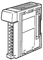
This section describes the general features, system configuration, and word allocation of the CQM1-B7A@@ Interface Units.
1-1 |
Features |
. . . . . . . . . . . . . . . . . . . . . . . . . . . . . . . . . . . . . . . . . . . . . . . . . . . . . . |
4 |
1-2 |
System Configuration . . . . . . . . . . . . . . . . . . . . . . . . . . . . . . . . . . . . . . . . . . . |
5 |
|
1-3 |
Connecting Devices . . . . . . . . . . . . . . . . . . . . . . . . . . . . . . . . . . . . . . . . . . . . |
5 |
|
|
1-3-1 |
CPU. . . . . . . . . . . . . . . . . . . . . . . . . . . . . . . . . . . . . . . . . . . . . . . . . . |
5 |
|
1-3-2 |
B7A Link Terminal. . . . . . . . . . . . . . . . . . . . . . . . . . . . . . . . . . . . . . |
5 |
1-4 |
Word Allocation . . . . . . . . . . . . . . . . . . . . . . . . . . . . . . . . . . . . . . . . . . . . . . . |
6 |
|
1-5 |
Bit Allocation . . . . . . . . . . . . . . . . . . . . . . . . . . . . . . . . . . . . . . . . . . . . . . . . . |
7 |
|
3

Features |
Section 1-1 |
1-1 Features
•The CQM1-B7A@@ Interface Unit incorporates the B7A transmission operations for the CQM1H/CQM1 I/O Unit.
•The following five models of CQM1H/CQM1 B7A Interface Unit are available.
Model |
|
No. of points |
|
|
|
|
|
|
|
Input |
Output |
|
|
|
|
CQM1-B7A21 |
16 |
|
16 |
|
|
|
|
CQM1-B7A13 |
32 |
|
0 |
|
|
|
|
CQM1-B7A03 |
0 |
|
32 |
|
|
|
|
CQM1-B7A12 |
16 |
|
0 |
|
|
|
|
CQM1-B7A02 |
0 |
|
16 |
|
|
|
|
Differences Between
CQM1-B7A01 and
CQM1-B7A21
•Each Unit can be connected to the same number of points on 16-point B7A Link Terminals as provided by the Unit. For example, two B7A Link Terminal Units with 16 input points each can be connected to a CQM1B7A13.
•The transmission delay time can be switched between STANDARD (19.2 ms rated) or RAPID (3 ms rated).
•The data processing when a transmission error occurs can be switched between HOLD (see note 1) and LOAD OFF (see note 2).
•The CPU treats the B7A Interface Units as the equivalent number of points. It can handle remote I/O equipment, such as switches and lamps, without recognizing communications.
Note 1. HOLD: When an error occurs, the input bit status immediately prior to the error is held.
2. LOAD OFF: When an error occurs, all input bits turn off.
The B7A Link Terminal is a terminal board that incorporates a communication function, connects to external I/O devices, and communicates with a PC over a single cable, thus reducing wiring effort.
CQM1-B7A21 is an upgraded version of the CQM1-B7A01 and can replace the CQM1-B7A01.
The features listed in the table below have been added to the CQM1-B7A21.
Item |
CQM1-B7A01 |
CQM1-B7A21 |
|
|
|
Transmission delay time |
STANDARD only |
STANDARD/RAPID |
|
|
switchable |
|
|
|
Transmission error |
HOLD |
HOLD/LOAD OFF switchable |
processing |
|
|
|
|
|
Note CQM1-B7A01 is no longer in production. Use the upgraded CQM1-B7A21.
4
System Configuration |
Section 1-2 |
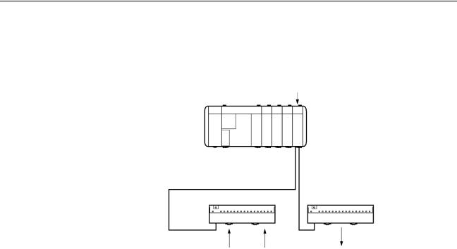
1-2 System Configuration
The following is a CQM1H/CQM1 system configuration with a B7A Interface
Unit.
B7A Interface Unit
CQM1H/CQM1
Transmission distance: 500 m max.
B7A Link Terminal (for input) B7A Link Terminal (for output)
Switch |
Sensor |
Lamps |
Note The maximum transmission distance depends on the transmission delay time and the power supply wiring.
Refer to 3-1 Connections to B7A Link Terminals.
1-3 Connecting Devices
1-3-1 CPU
The B7A Interface Unit connects to the following CPUs.
Name |
Model |
CQM1H-series CPU |
CQM1H-CPU11 |
|
CQM1H-CPU21 |
|
|
|
CQM1H-CPU51 |
|
|
|
CQM1H-CPU61 |
|
|
CQM1-series CPU |
CQM1-CPU11-E |
|
CQM1-CPU21-E |
|
CQM1-CPU41-EV1 |
|
CQM1-CPU42-EV1 |
|
CQM1-CPU43-EV1 |
|
CQM1-CPU44-EV1 |
|
|
1-3-2 B7A Link Terminal
The B7A Interface Unit connects to the following 16-point B7A Link Terminals with a standard I/O delay of 19.2 ms (typical).
Input
Name |
Model |
Transmission delay time |
Screw terminal models |
B7A-T6@1 |
STANDARD (19.2 ms) |
|
B7AS-T6@1 |
|
|
B7A-T6@6 |
RAPID (3 ms) |
|
B7AS-T6@6 |
|
Module models |
B7A-T6D2 |
STANDARD (19.2 ms) |
|
B7A-T6D7 |
RAPID (3 ms) |
|
|
|
PC connector models |
B7A-T@E3 |
STANDARD (19.2 ms) |
|
B7A-T@E8 |
RAPID (3 ms) |
5

Word Allocation |
|
Section 1-4 |
|
Output |
|
|
|
|
|
|
|
|
Name |
Model |
Transmission delay time |
|
|
|
|
|
Screw terminal model |
B7A-R6@@1 |
STANDARD (19.2 ms) |
|
|
|
|
|
|
B7AS-R6@@1 |
|
|
|
|
|
|
|
B7A-R6@@6 |
RAPID (3 ms) |
|
|
|
|
|
|
B7AS-R6@@6 |
|
|
|
|
|
|
Module model |
B7A-R6A52 |
STANDARD (19.2 ms) |
|
|
|
|
|
|
B7A-R6A57 |
RAPID (3 ms) |
|
|
|
|
|
PC connector models |
B7A-R@A@3 |
STANDARD (19.2 ms) |
|
|
|
|
|
|
B7A-R@A@8 |
RAPID (3 ms) |
Note Combine B7A Interface Units and B7A Link Terminals with equal transmission delay times.
Transmission errors will occur if the transmission delay times used in the combination are not equal.
Do not connect B7A Link Terminals with 10 points and I/O mixed points. Connect only 16-point transmission models.
1-4 Word Allocation
The CPU treats the B7A Interface Unit as an equivalent number of connected I/O Units. The words allocation is identical to that for I/O Units, with inputs and outputs allocated from left to right.
6

Bit Allocation |
Section 1-5 |
Words from 000 including the input bits incorporated by the CPU are allocated for input and words from 100 are allocated for output as shown in the following illustration. Refer to the CQM1H or CQM1 Operation Manual for details on I/O word allocation.
CQM1H/CQM1 |
|
|
IN B7A12 |
IN |
B7A21 |
Word |
|
|
16 |
16 |
|
pts |
pts |
|
B7A Link Terminal (for input)
Word 001
Points: 0 to 15
Bit no.: 00100 to 00115
B7A Link Terminal (for input)
Word 003
Points: 0 to 15
Bit no.: 00300 to 00315
|
|
|
PS |
: Power Supply Unit |
|
OUT |
B7A03 |
|
CPU |
: CPU |
|
|
IN |
: Input Unit and terminals |
|||
|
|
|
OUT |
: Output Unit |
|
|
|
|
B7A21 |
: B7A Interface Unit |
|
|
|
|
|
(16 input and 16 output points) |
|
16 |
|
|
B7A12 |
: B7A Interface Unit |
|
|
|
|
(16 input points) |
||
pts |
|
|
B7A03 |
: B7A Interface Unit |
|
terminals 1 |
|
terminals 2 |
|
(16 output points) |
|
|
|
|
|
||
Connection |
|
Connection |
|
B7A Link Terminal (for output) |
|
|
|
|
|
||
|
|
|
Word 103 |
|
|
|
|
|
|
Points: |
0 to 15 |
|
|
|
|
Bit no.: |
10300 to 10315 |
|
|
|
|
B7A Link Terminal (for output) |
|
|
|
|
Word 102 |
|
|
|
|
|
|
Points: |
0 to 15 |
|
|
|
|
Bit no.: |
10200 to 10215 |
B7A Link Terminal (for output)
Word 100
Points: 0 to 15
Bit no.: 10000 to 10015
1-5 Bit Allocation
The bit allocation for each model is described below.
CQM1-B7A21
I/O |
Word no. |
Termi- |
|
|
Bit |
|
|
|
|
nal |
|
|
|
|
|
|
|
15 |
14 to 12 |
11 to 8 |
7 to 4 |
3 to 0 |
|
Input |
n |
1 |
See |
Input bits |
|
|
|
|
(see note 2) |
|
note 1 |
|
|
|
|
|
|
|
|
|
|
|
|
Output |
m |
2 |
Output bits |
|
|
||
(see |
(see note 2) |
|
|
|
|
|
|
note 3) |
|
|
|
|
|
|
|
|
|
|
|
|
|
|
|
7
I/O |
Word no. |
Termi- |
|
|
Bit |
|
|
|
|
nal |
|
|
|
|
|
|
|
15 to 12 |
11 to 8 |
|
7 to 4 |
3 to 0 |
|
Output |
m |
1 |
Output bits |
|
|
|
|
(see |
|
|
|
|
|
|
|
note 3) |
|
|
|
|
|
|
|
|
|
|
|
|
|
|
|
Output |
m + 1 |
2 |
Output bits |
|
|
|
|
(see |
|
|
|
|
|
|
|
note 3) |
|
|
|
|
|
|
|
|
|
|
|
|
|
|
|
|
I/O |
Word no. |
Termi- |
|
|
|
|
|
Bit |
|
|
|
|
|
|
|
nal |
|
|
|
|
|
|
|
|
|
|
|
|
|
|
15 |
14 to 12 |
11 to 8 |
|
7 to 4 |
3 to 0 |
|
|||
|
Input |
n |
1 |
|
See note |
Input bits |
|
|
|
|
|
||
|
|
|
|
|
1 |
|
|
|
|
|
|
|
|
|
|
|
|
|
|
|
|
|
|
|
|
|
|
|
|
|
|
|
|
|
|
|
|
|
|
|
|
|
I/O |
Word no. |
Termi- |
|
|
|
|
Bit |
|
|
|
|
|
|
|
|
nal |
|
|
|
|
|
|
||||
|
|
|
|
15 to 12 |
11 to 8 |
7 to 4 |
3 to 0 |
||||||
|
Output |
m |
1 |
|
|
Output bits |
|
|
|
|
|
|
|
|
(see |
|
|
|
|
|
|
|
|
|
|
|
|
|
note 3) |
|
|
|
|
|
|
|
|
|
|
|
|
Note 1. Bit 15 of the input address is allocated as follows, according to the DIP |
|||||||||||||
|
switch input mode setting. |
|
|
|
|
|
|
Section 1-5 |
|||||
Bit Allocation |
|
|
|
|
|
|
|
|
|
||||
CQM-B7A13 |
|
|
|
|
|
|
|
|
|
|
|
|
|
|
I/O |
Word no. |
Termi- |
|
|
|
|
Bit |
|
|
|
|
|
|
|
|
nal |
15 |
14 to 12 |
11 to 8 |
|
7 to 4 |
3 to 0 |
||||
|
Input |
n |
1 |
|
See |
Input bits |
|
|
|
|
|
||
|
|
|
|
|
note 1 |
|
|
|
|
|
|
|
|
|
Input |
n + 1 |
2 |
|
See |
Input bits |
|
|
|
|
|
||
|
|
|
|
|
note 1 |
|
|
|
|
|
|
|
|
CQM1-B7A03 |
|
|
|
|
|
|
|
|
|
|
|
|
|
CQM1-B7A12 |
|
|
|
|
|
|
|
|
|
|
|
|
|
CQM1-B7A02 |
|
|
|
|
|
|
|
|
|
|
|
|
|
15-point input + 1 error mode setting = transmission error bit
16-point input = input bit 15 Refer to 2-2 Switch Settings.
2. Start word address (n: input, m: output)
3. See the following caution.
!Caution The minimum input time (minimum required time to read input signal from CPU) at output bit of the B7A Interface Unit is as follows:
Transmission delay time |
Minimum input time |
|
|
STANDARD (19.2 ms) |
16 ms |
|
|
RAPID (3 ms) |
2.4 ms |
|
|
When a user program is created, make sure the ON/OFF signal range from |
|
the CPU to the B7A Interface Unit’s output bit is larger than the above values. |
|
If smaller than the above values, data might not be correct transmitted. |
|
Transmission Errors
Power On |
If the input mode is set to 15IN+ERR, the transmission error bit becomes OFF |
|
when the CQM1H/CQM1 power is turned on. |
|
The transmission error bit turns ON if normal transmission with the input B7A |
|
Link Terminal is not established within 10 ms. |
|
All input bits remain OFF from the time CQM1H/CQM1 is turned on until nor- |
|
mal transmission is established. |
8

Bit Allocation |
Section 1-5 |
Inputs |
When a transmission error occurs, the input bits are processed according to |
|
the transmission error processing setting: HOLD or LOAD OFF. |
|
If the input mode is set to 15IN+ERR, the transmission error bit turns ON. |
|
The transmission error bit turns OFF when normal transmission is re-estab- |
|
lished. |
|
The normally received signals are then input to the input bits. |
Outputs |
A transmission error with an output B7A Link Terminal can only be detected at |
|
the Link Terminal. Confirm the error with the Link Terminal ERR indicator and |
|
error output. |
9
SECTION 2
Nomenclature and Settings
This section provides the nomenclature and switch settings for the CQM1-B7A@@ Interface Units.
2-1 |
Nomenclature . . . . . . . . . . . . . . . . . . . . . . . . . . . . . . . . . . . . . . . . . . . . . . . . . |
12 |
2-2 |
Switch Settings . . . . . . . . . . . . . . . . . . . . . . . . . . . . . . . . . . . . . . . . . . . . . . . . |
17 |
11
Loading...