


 Loading...
MAINTENANCE MANUAL
USG-400
ISSUE 1 2011/11

|
|
|
USG-400 |
|
|
|
|
|
|
CONTENTS |
|
Chapter 1 : Product Outline................................................................... |
1-1 |
||
1 |
Outline ................................................................................................................................. |
1-2 |
|
2 |
Features............................................................................................................................... |
1-2 |
|
3 |
Limitations........................................................................................................................... |
1-3 |
|
4 |
System chart ....................................................................................................................... |
1-4 |
|
Chapter 2 : Specifications ..................................................................... |
2-1 |
||
1 |
Specifications ..................................................................................................................... |
2-2 |
|
Chapter 3 : Installation and Connection............................................... |
3-1 |
||
1 |
Installation workflow .......................................................................................................... |
3-2 |
|
2 |
Installation of the ultrasonic generator ............................................................................ |
3-3 |
|
3 |
Connection of compatible electrosurgical generator |
|
|
|
(when using the THUNDERBEAT) .................................................................................... |
3-4 |
|
4 |
Connection to power supply (Ultrasonic Generator) ..................................................... |
3-11 |
|
5 |
Automatic mist & smoke evacuation system/function |
|
|
|
(When using the compatible high flow insufflation unit) ............................................. |
3-12 |
|
6 |
Connection of footswitch (optional) ............................................................................... |
3-15 |
|
7 |
Connection of the THUNDERBEAT and/or SONICBEAT |
|
|
|
(various options available).............................................................................................. |
3-17 |
|
Chapter 4 : Care, Storage, and Disposal .............................................. |
4-1 |
||
1 |
Care |
...................................................................................................................................... |
4-2 |
2 |
Storage ................................................................................................................................ |
4-3 |
|
3 |
Disposal............................................................................................................................... |
4-3 |
|
Chapter ............................................................................5 : Inspection |
5-1 |
||
1 |
Verification ..........................................................................................................workflow |
5-2 |
|
2 |
Power ...............................................................................................................verification |
5-3 |
|
3 |
Verification of communication cable connection between compatible electrosurgical |
||
|
generator ........................and ultrasonic generator (when using the THUNDERBEAT) |
5-6 |
|
4 |
Verification ...............................................................of touch-screen and push buttons |
5-7 |
|
5 |
Verification ...............................................of the THUNDERBEAT and/ or SONICBEAT |
5-10 |
|
6 |
Verification .............................................................................of footswitch connection |
5-13 |
|
7 |
Verification of the high-frequency(RF bipolar) output |
|
|
|
(when ..................................................................................using the THUNDERBEAT) |
5-13 |
|
8 |
Verification ......................................................................................of the alarm system |
5-17 |
|
9 |
Procedure .............................................................................................after verification |
5-19 |
|
10 Inspection ....................................................................................................check sheet |
5-20 |
||
Chapter ........................................................................6 : Safety check |
6-1 |
||
1 |
Check ..............................................................................................................procedures |
6-2 |
|
|
1-1 ...................................................................................... |
Grounding Resistance confirmation |
6-2 |
|
1-2 ....................................................................................Ground leakage current confirmation |
6-2 |
|
|
1-3 ...............................................................................Enclosure leakage current confirmation |
6-2 |
|
|
1-4 .....................................................................................Patient leakage current confirmation |
6-3 |
|
|
1-5 .......................................................................................................... |
Leakage current criteria |
6-5 |
2 |
Check ..........................................................................................................................Card |
6-6 |
|
ISSUE1 |
1 |
Contents |

USG-400
Chapter 7: Block Diagram ..................................................................... |
7-1 |
|
1 |
Block Diagram..................................................................................................................... |
7-2 |
Chapter 8 : Troubleshooting ................................................................. |
8-1 |
|
1 |
Troubleshooting.................................................................................................................. |
8-2 |
2 |
Error screen ........................................................................................................................ |
8-3 |
3 |
Troubleshooting guide....................................................................................................... |
8-3 |
3 |
Returning the ultrasonic generator for repair................................................................ |
8-22 |
Contents |
2 |
ISSUE1 |

USG-400
INTRODUCTION
Introduction
Repair and maintenance of this product requires highly specialized knowledge and techniques. We recommend that you contact an Olympus service center in your area if a problem develops with the product.
If repairs or modifications are made by personnel not authorized by Olympus, the warranty is void, and Olympus shall not be liable for damage that occurs to or as a result of use of the modified product.
Applicable Unit
USG-400
Copyright
Unauthorized reproduction or distribution in part or in whole is prohibited.
Trademarks
OLYMPUS is a registered trademark of Olympus Corporation.
INTRODUCTION |
1 |
ISSUE1 |

USG-400
Chapter 1 : Product Outline
1 |
Outline................................................................................................ |
1-2 |
2 |
Features ............................................................................................. |
1-2 |
3 |
Limitations ......................................................................................... |
1-3 |
4 |
System chart...................................................................................... |
1-4 |
ISSUE1 |
1-1 |
Product Outline |

USG-400
1 Outline
(1)Purpose of Use
The THUNDERBEAT instruments are intended for use of coagulation/cutting of tissue and sealing/cutting of vessels in combination with the ultrasonic generator, the electrosurgical generator and the THUNDERBEAT transducer that are specified by Olympus in general surgery (including endscopic and microscopic surgery)
(2)Allowable Combinations
This product can be used in combination with the products listed in system diagram.
2Features
(1)This product, which has two handpiece connectors, enables dissection and coaguration of body tissues by plugging the handpieces int their corresponding handpiece connectors.
THUNDERBEAT Connector (Handpiece Connector 1) : SEAL & CUT output / SEAL output SONICBEAT Connector (Handpiece Connector 2) : Ultrasonic output
(2)PLL resonance tracking control and constant current control enable stable ultrasonicvibration.
(3)Various setting are shown on the touch-panel LCD. They can be changed on the display.
(4)All the devices have their own hand switches that enable ON/OFF control of output.
(5)All the devices have their own foot switches that enable ON/OFF control of output.
(6)This product has the interface for output interlock and the output can be controlled.
Combination of ESG-400 and MAJ-1871 enable use of combine output.
Combination of UHI-2 or UHI-3 and MAJ-1871 or MAJ-1872 and MAJ-1873 enable use of automatic fume control function.
Combination of UHI-4 and MAJ-1871 or MAJ-1872 enable use of automatic fume contril function.
(7)This product has the “setting selection” function that allows the user to arrange , and various settings saved in advance can be called us easily.
(8)Its interface for PC communication enable use of the followingfunctions.(User unidentified)
Software Upgrading
Download and Upload of log data.
(9)The language shown on LCD can be selected from eight languages.
(10)As a result of introduction of the corporate product design, its desigh is consistent with the desighs of products in hte same generation.
(11)This product can be connected to ENDOALPHA-3 system.
Product Outline |
1-2 |
ISSUE1 |

USG-400
3Limitations
(1)Use this product under the supervision of a doctor at a medical facility.
(2)Do not use this product in combination with the products other than those designated by Olympus.
(3)This product should be used, transported or stored in the following environment. 1)Usage environment
Ambient temperature |
10 |
- 40°C |
Relative humidity |
30 |
- 85% |
Atmospheric pressure |
70 |
- 106kPa |
Altitude |
3000m or less |
|
(Do not use this product in the combustible atmosphere) 2)Transportation/storage environment
Ambient temperature |
-25 - 70°C |
Relative humidity |
10 - 90% |
Atmospheric pressure |
70 - 106kPa |
(4) Power source |
|
1)Voltage, current |
|
J type |
100V, 3A |
A type |
120V, 3A |
E type |
220 - 240V, 1.5A |
2)Frequency |
50/60Hz |
3)Voltage variation |
Within ±10% |
4)Frequency variation |
Within ±1Hz |
ISSUE1 |
1-3 |
Product Outline |

USG-400
4 System chart
Product Outline |
1-4 |
ISSUE1 |
USG-400
Chapter 2 : Specifications
1 |
Specifications.................................................................................... |
2-2 |
ISSUE1 |
2-1 |
Specifications |
USG-400
1Specifications
○Ultrasonic Generator USG-400
Power supply |
Rated voltage |
120 V AC |
(USA model) |
|
|
220 - 240 V AC |
(EU model) |
|
Voltage fluctuation |
Within ±10% |
|
|
Rated frequency |
50/60 Hz |
|
|
Frequency fluctuation |
Within ±1 Hz |
|
|
Rated input |
360VA |
|
|
Fuse rating |
4A,250VA |
|
|
Fuse size |
Φ5 X 20mm |
|
Size |
Dimensions |
375(w)X156(H)X480(D)mm |
|
|
|
|
|
|
Weight |
9 kg |
|
Classification |
Type of protection |
Class I |
|
(medical |
against electric shock |
|
|
|
|
||
electrical |
Degree of protection |
|
|
equipment) |
against electric |
CF type |
|
|
shock of applied part |
|
|
|
Degree of protection |
The ultrasonic generator should be kept away from |
|
|
against explosion |
flammable gases. |
|
Output |
The applicable |
THUNDERBEAT/SONICBEAT |
|
|
instrument |
|
|
|
ON/OFF operation |
Footswitch |
|
|
|
Handswitch |
|
|
Output setting |
Setting possible in the Set Screen displayed |
|
|
|
on the touch panel. |
|
|
Frequency |
47.0kHz |
|
|
Duty cycle |
1 min. ON/1min. OFF |
|
|
(Recommended cycle) |
||
|
|
|
|
Medical |
|
This device complies with the requirements of Diretive |
|
Devices |
|
93/42/EEC concerning medical devices. |
|
Directive |
|
Classification: Class b |
|
This device complies with the EMC requirements of EN 60601-1-2:2007 when used in combination with devices bearing CE marking either on the products or in its instructions for use.
Emission: Class B of EN 55011
EMC |
Applied standard |
The ultrasonic generator complies with the standards |
||||
|
IEC 60601-1-2:2001 |
listed in the left column. |
|
|
|
|
|
(2007) |
|
|
|
|
|
|
|
CISPR 11 of emission: |
|
|
|
|
|
|
Group 1,Class B |
|
|
|
|
|
|
The ultrasonic generator complies with the EMC standard |
||||
|
|
for medical electrical |
equipment; |
edition |
3(IEC |
|
|
|
60601-1-2:2007).However, when connecting to an |
||||
|
|
instrument that complies with the EMC standard for |
||||
|
|
medical |
electrical |
equipment, |
edition |
1(IEC |
|
|
60601-1-2:1993), the whole system complies with edition |
||||
|
|
1. |
|
|
|
|
|
|
When the ultrasonic generator is combined with the |
||||
|
|
compatible electrosurgical generator, the EMC |
||||
|
|
information shall comply with the compatible |
||||
|
|
electrosurgical generator. |
|
|
||
Specifications |
2-2 |
ISSUE1 |

USG-400
WEEE Directive
Year of manufacture
In accordance with European Directive 2002/96/EC on Waste Electrical and Electronic Equipment, this symbol indicates that the product must not be disposed of as unsorted municipal waste, but should be collected separately.
Refer to your local Olympus distributor for return and/or collection systems available in your country.
The last digit of the year of manufacture is given in the second digit of the serial number.
○Footswitch for THUNDERBEAT (MAJ-1870, optional)/ Footswitch for SONICBEAT (MAJ-1869, optional)
Classification |
Degree of water |
IEC60529 IPX8 water tight type |
(medical |
resistance |
(except the plug section) |
electrical |
Degree of protection |
IEC6060101AP type |
equipment) |
against explosion |
|
|
|
|
Size |
Dimensions |
346(w)X64(H)X486(D)mm |
|
|
|
|
Weight |
2.3 kg |
|
|
|
|
Length of the cord |
4000 mm |
○ Communication Cable 0.25m (MAJ-1871, optional)
Size |
Weight |
0.04kg |
|
|
|
|
Length of the cord |
250 mm |
|
|
|
○ Communication Cable 10m (MAJ-1871, optional)
Size |
Weight |
0.5kg |
|
|
|
|
Length of the cord |
10,000 mm |
|
|
|
○ Adapter for UHI-2/3 (MAJ-1873, optional)
|
Size |
Dimensions |
94(w)X37(H)X71(D)mm |
|
|
Weight |
215 g |
|
|
|
|
|
Applicable |
|
MAJ-1871, MAJ-1872 |
|
Cables |
|
|
|
|
|
|
○ Docking Fixture (MAJ-1876, optional)
Screws |
14 pcs |
Hex wrench |
1 pc |
|
|
Ficture plates |
2pcs |
ISSUE1 |
2-3 |
Specifications |

USG-400
Chapter 3 : Installation and Connection
1 |
Installation workflow......................................................................... |
3-2 |
2 |
Installation of the ultrasonic generator ........................................... |
3-3 |
3 |
Connection of compatible electrosurgical generator |
|
|
(when using the THUNDERBEAT) .................................................... |
3-4 |
4 |
Connection to power supply(Ultrasonic Generator) .................... |
3-11 |
5 |
Automatic mist & smoke evacuation system/function |
|
|
(When using the compatible high flow insufflation unit) ............. |
3-12 |
6 |
Connection of footswitch (optional) .............................................. |
3-15 |
7 |
Connection of the THUNDERBEAT and/or SONICBEAT |
|
|
(various options available) ............................................................. |
3-17 |
ISSUE1 |
3-1 |
Installation and Connection |

USG-400
Prepare the ultrasonic generator and ancillary equipment for the intended purpose by referring to “System chart” in the Product Outline. Install and connect the ultrasonic generator and ancillary equipment as described in the following sections and also by referring to the instruction manuals for the ancillary equipment.
1 Installation workflow
The following is the equipment installation workflow. For detailson each step, read the corresponding description.
1.Section 2 “Installation of the ultrasonic generator”
2.Section 3 “Connection of compatible electrosurgical generator (when using the THUNDERBEAT)”
3.Section 4 “Connection to power supply (Ultrasonic Generator)”
4.Section 5 “Automatic mist & smoke evacuation system/function (when using the compatible high flow insufflation unit)”
5.Section 6 “Connection of the footswitch(es)”
6.Section 7 “Connection of the THUNDERBEAT and/or SONICBEAT”
Installation and Connection |
3-2 |
ISSUE1 |
USG-400
2 Installation of the ultrasonic generator
CAUTION
Heed the following cautions when installing the ultrasonic generator in a position other than on the energy cart shown in the “System chart” in the Product Outline.
−Install the ultrasonic generator on a level, stable platform.
If the ultrasonic generator slips from or topples down from an u nstable installation position, the patient, surgeon and/or surgical staff may be injured. Furthermore, equipment damage may occur.
−Confirm that the installation position has enough strength and size for supporting the ultrasonic generator. If it is not strong enough, the ultrasonic generator may fall and be damaged.
Be careful when the trolley (cart) containing the ultrasonic generator and other equipment are transported on a non-level surface or across an obstacle cable. If the trolley (cart) is transported over an obstacle, the ultrasonic generator and other equipment may tip over possibly resulting in equipment failure.
Do not install the ultrasonic generator on its side or upside down.
Otherwise, a failure or malfunction may occur.
Do not install the ultrasonic generator in close contact with a wall or other equipment in a manner that would block the ventilation opening. Otherwise, the generator may overheat.
Be careful not to pinch a hand when installing the ultrasonic generator.
Avoid applying excessive force on the socket connections.
Otherwise, wire disconnection or other failure may occur.
Always use the ultrasonic generator in compliance with the “Operating environment” specified in the Product Outline. Otherwise, the ultrasonic generator may fail.
NOTE
Keep the instruction manual in an easily accessible place near the ultrasonic generator.
Before connecting an accessory to the ultrasonic generator, read And understand the instruction manual for the accessory thoroughly and confirm the compatibility of the ultrasonic generator.
1. Checking the operationg conditions
Confirm that the operating conditions comply with the information provided in “Danger, warnings, and cautions.
2. Installing the trolley (cart)
When using the energy cart TC-E400, prepare the cart by following its instruction manual.
3. Installing the ultrasonic generator
Place the ultrasonic generator on a stable trolley (cart) or a level, stable platform. Use of the energy cart TC-E400 is highly recommended.
ISSUE1 |
3-3 |
Installation and Connection |

USG-400
3 Connection of compatible electrosurgical generator (when using the THUNDERBEAT)
WARNING
Never connect a cable other than the optional communication cable to the ultrasonic generator. Otherwise, the ultrasonic generator cannot perform appropriately and injury or equipment damage may result.
CAUTION
Avoid applying excessive force on the communication cable.
Otherwise, wire disconnection or other failure may result.
Be sure to retain the docking plug cover. If it is lost, the ultrasonic generator cannot be used in the standalone configuration.
Be sure not to lose the tools such as screws and fixture plates. If these items are lost, the ultrasonic generator cannot be connected to the compatible electrosurgical generator.
Connect the docking connector and docking plug correctly.
Otherwise, malfunction or ultrasonic generator damage may result.
Avoid getting liquid inside the ultrasonic generator.
Otherwise, it may be damaged.
Avoid applying excessive force on the docking connector,
docking plug and fixture plates. Otherwise, they may be damaged.
Heed the following cautions when assembling the docking connector and docking plug:
−Be careful not to pinch a finger.
−Be careful not to drop a screw in the area around the docking plug.
Connect the docking plug to the docking connector properly. Improper connection such as oblique insertion or contamination may cause output irregularities.
Securely fix the fixture plates on the compatible electrosurgical generator. Otherwise, the compatible electrosurgical generator may fall.
Remove the fixture plate prior to lifting the compatible electrosurgical generator. Otherwise, the fixture plates may be damaged.
Do not remove screws other than those screws that are instructed to do so in the manual.
Disconnect the docking connector and/or the docking plug properly as described in “Disconnection” on page 3-10 Otherwise, the ultrasonic generator, docking connector and/or docking plug may be damaged.
Before connecting the compatible electrosurgical generator, be sure that the power cord of the ultrasonic generator is
unplugged from the AC power socket on the ultrasonic generator.
When removing the docking plug cover, be careful to maintain pressure on the cover, because the docking plug is spring-loaded.
Installation and Connection |
3-4 |
ISSUE1 |

USG-400
The THUNDERBEAT performs cutting and coagulation using high frequency (RF bipolar) and ultrasonic energy. When it is used, both the compatible electrosurgical and ultrasonic generators are required.
To transmit the high-frequency (RF bipolar) energy from the compatible electrosurgical generator to the ultrasonic generator, a docking connector and docking plug are provided on each of these generators.
To connect the two generators, align the docking connector at the bottom of the compatible electrosurgical generator into the docking plug at the top of the ultrasonic generator.
After the alignment is made, the compatible electrosurgical generator is placed on top of ultrasonic generator (see Figure 3.1).
This section describes how to connect and disconnect the docking connector and docking plug.
Figure 3.1
Connection
1.Preparing the docking fixture
Prepare the docking fixture (MAJ-1876).
The docking fixture includes the tools for use in connection, including
2 fixture plates, 14 screws (12 pcs for the fixture plates and 2 pcs for the docking plug cover) and a hex wrench.
All of the screws used in the connection between the compatible electrosurgical generator and ultrasonic generator should be tightened/loosened using the hex wrench.
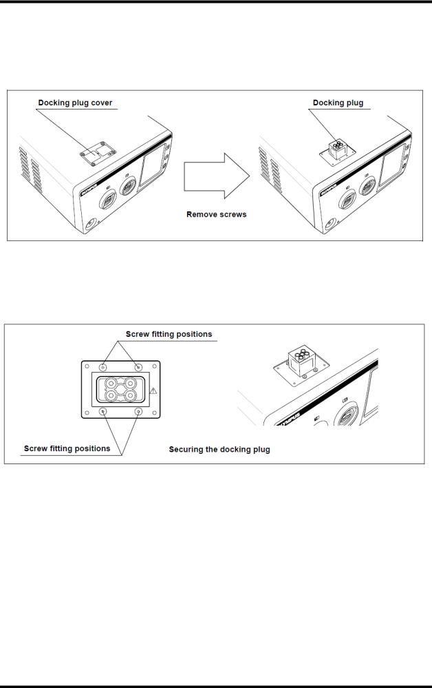
2. Checking the docking plug cover
Confirm the position of the docking plug cover, which is a rectangular plate on the top panel (near front) of the ultrasonic generator (see Figure 3.2).
Behind the docking plug cover is the docking plug for connection of the compatible electrosurgical generator.
ISSUE1 |
3-5 |
Installation and Connection |
USG-400
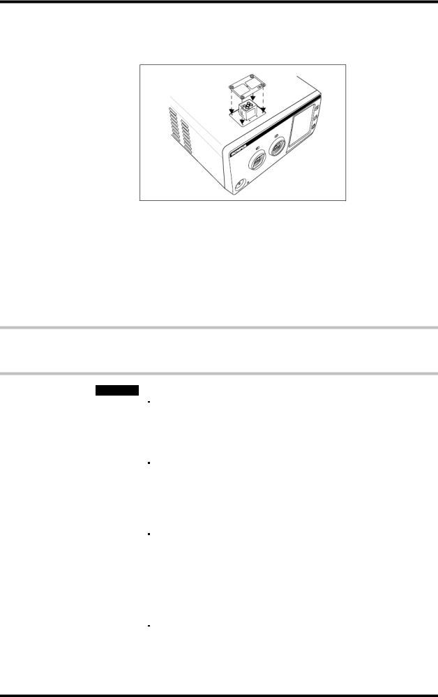
3. Removing the docking plug cover
Holding the docking plug cover, remove four screws from the docking plug cover (see Figure 3.2). Retain the docking plug cover.
Removing the docking plug cover exposes the docking plug.
Figure 3.2
4. Securing the docking plug
Insert the screws removed in step 3 into the four positions around the docking plug and tighten securely (see Figure 3.3).
Figure 3.3
5. Attaching the fixture plates to the ultrasonic generator
Attach the fixture plates on two positions at the top left and top right of the rear panel of the ultrasonic generator using three screws for each plate (see Figure 3.4).
Installation and Connection |
3-6 |
ISSUE1 |
USG-400
Figure 3.4
6. Connectiong
Align the rear panel of the compatible electrosurgical generator with the fixture plates and then lower the front edge of the compatible electrosurgicalgenerator slowly (see Figures 3.5 and 3.6).
Align the compatible electrosurgical generator with the fixture plates ensures alignment of the docking plug and docking connector.
Figure 3.5
ISSUE1 |
3-7 |
Installation and Connection |

USG-400
Figure 3.6
7. Attaching the fixture plates to the compatible electrosurgical generator attach the fixture plates that have been attached to the rear panel of the ultrasonic generator to the compatible electrosurgical generator using three screws for each plate (see Figure 3.7).
The fixture plates ensure tight clamping of the two generators.
Figure 3.7
8. Storing the docking plug cover
Attach the docking plug cover, which has been removed in step 3 above, to the threaded holes for the docking plug cover on the rear panel of the ultrasonic generator using two screws (see Figure 3.8).
Installation and Connection |
3-8 |
ISSUE1 |

USG-400
Figure 3.8
9. Storing the tool
Store the hex wrench in a nearby location such as the drawer of the cart.
10. Connecting the communication cable 0.25m
Connect the LINK-IN and LINK-OUT plugs of the communication cable 0.25 m to the communication connectors on the rear panels of the ultrasonic
generator and compatible electrosurgical generator. After connection, secure each plug by pushing it in while turning the screws on both sides of the plug (see Figure 3.9).
Example: Connect the communication cable 0.25 m LINK-IN plug to the LINK-IN connector on the rear panel of the ultrasonic generator and connect the communication cable 0.25 m LINK-OUT plug on the other end to the communication connector on the rear panel of the compatible electrosurgical generator.
Figure 3.9
ISSUE1 |
3-9 |
Installation and Connection |
USG-400
Disconnection
1.Preparing the stored tool
Prepare the hex wrench that has been stored after the connection.
All screws used in this disconnection should be handled by the hex wrench.
2.Disconnecting the communication cable 0.25m
Loosen the plugs of the communication cable 0.25 m connected to the rear panels of the ultrasonic generator and compatible electrosurgical generator by loosening the screws on both sides of each plug by hand, and then unplug the plugs.
3.Removing the docking plug cover
Remove the docking plug cover from the rear panel of the ultrasonic generator.
4.Removing the fixture plates from the compatible electrosurgical generator remove screws from the fixture plates attached to the rear panel of the compatible electrosurgical generator.
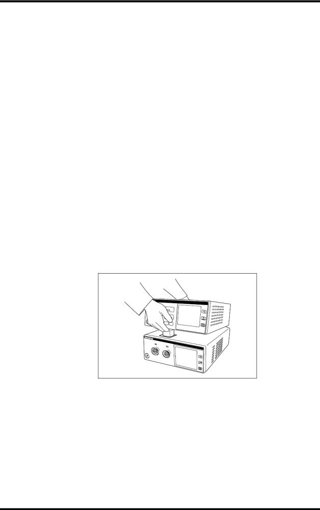
5.Separating the generators
Hold the front side of the compatible electrosurgical generator and lift it (see Figure 3.10).
6.Removing the docking plug screws.
Remove screws from the four positions around the docking plug.
7.Removing the fixture plates from the ultrasonic generator.
Remove screws from the fixture plates attached to the rear panel of the ultrasonic generator.
Figure 3.10
Installation and Connection |
3-10 |
ISSUE1 |
USG-400
8. Secureing the docking plug
Place the docking plug cover on the docking plug and push the cover slowly with your hand to cover the docking plug (see Figure 3.11).
Figure 3.11
9. Secureing the docking plug cover
Attach the screws that have been removed in step 7 on the four corners of the docking plug cover.
10. Storing the parts and tools
Store the removed fixture plates X 2, screws X 14 and the hex wrench.
4 Connection to power supply (Ultrasonic Generator)
WARNING
Connect the power cord firmly so that it is not unplugged accidentally during operation, and avoid excessive bending, straining or twisting. Otherwise, the power cord may become unplugged or damaged. If damaged, an electric shock or fire hazard may result.
The ultrasonic generator requires grounding for safety. To avoid an electric shock, always connect the power cord plug to a properly grounded hospital-grade 3-conductor power outlet. Do not use an adapter that converts the 3-conductor power plug into a 2-conductor plug because this may impair the safety of the unit.
Confirm that the power capacity of the hospital-grade power outlet to which the ultrasonic generator is connected is sufficient for all the equipment connected to it including the ultrasonic generator. If the power capacity of the power outlet is insufficient, a fire hazard may result and the circuit breaker of the hospital may trip, turning OFF all of the equipment connected to the power supply including the ultrasonic generator.
Do not use an extension cord and power strip in the power supply line. Otherwise, improper installation/connection may cause an electric shock hazard.
ISSUE1 |
3-11 |
Installation and Connection |
USG-400
CAUTION
Before connecting the power supply, make sure that it conforms to the power specifications described on the rating plate of the ultrasonic generator.
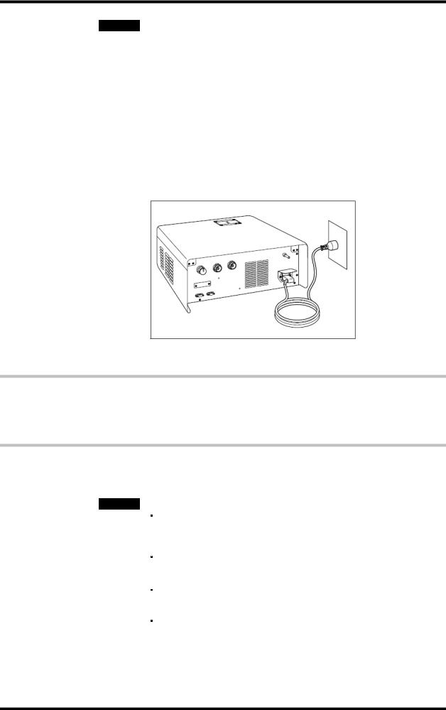
1. Connecting the power cord
Connect the power cord of the ultrasonic generator to the AC power socket on the rear panel of the ultrasonic generator (see Figure 3.12).
2. Connecting to the power outlet
Connect the power cord directly to a hospital-grade 3-conductor power outlet that meets the electrical rating inscribed on the rating plate of the ultrasonic generator (see Figure 3.12).
Figure 3.12
5 Automatic mist & smoke evacuation system/function (When using the compatible high flow insufflation unit)
When the THUNDERBEAT or SONICBEAT is activated, automatic mist & smoke evacuation system/function of UHI-2/3 work with activation simultaneously to evacuate the smoke and mist produced in the abdominal cavity.
CAUTION
When using the automatic mist & smoke evacuation system/function, also refer to the instruction manual for the compatible high flow insufflation unit.
Avoid applying excessive force to the communication cable.
Otherwise, wire disconnection or other failure may result.
The 2-way cable for aeration and extension cable for aeration are not allowed to use for the ultrasonic generator.
When using the ultrasonic generator with the compatible electrosurgical generator and the compatible high flow insufflation unit simultaneously, contact Olympus.
Installation and Connection |
3-12 |
ISSUE1 |

USG-400
1. Preparation
Prepare the adapter for UHI-2/3 and the communication cable 10 m.
The compatible high flow insufflation unit cannot be connected directly to the ultrasonic generator. The use of an adapter for UHI-2/3 is required for the connection.
2. Connecting the adapter for UHI-2/3
Connect the system plug of the adapter for UHI-2/3 to the system connector on the rear panel of the compatible high flow insufflation unit. After connection, secure the system plug by fasten the screws on both sides of the plug (see Figure 3.13).
3. Connecting the communication cable 10m to the adapter for UHI-2/3 Connect the plug of the communication cable 10 m to the LINK-IN or LINK-OUT connector of the adapter for UHI-2/3. After connection, secure each plug by pushing it in while turning the screws on both sides of the plug (see Figure 3.13).
4. Connecting the communication cable 10m (to the ultrasonic generator) Connect the other plug of the communication cable 10 m that has been connected to the adapter for UHI-2/3 to the LINK-IN or LINK-OUT connector of the ultrasonic generator. After connection, secure each plug by pushing it in while turning the screws on both sides of the plug (see Figure 3.13).
Figure 3.13
ISSUE1 |
3-13 |
Installation and Connection |
Loading...