


MAINTENANCE MANUAL
UES-40
ISSUE4
2008/01

UES-40
INTRODUCTION
Repair and maintenance of this product requires highly specialized knowledge and techniques.
We recommend that you contact an Olympus service center in your area if a problem develops with the product.
If repairs or modifications are made by personnel not authorized by Olympus, the warranty is void, and Olympus shall not be liable for damage that occurs to or as a result of use of the modified product.
Applicable Unit
• ELECTROSURGICAL UNIT UES-40 |
120 V |
• ELECTROSURGICAL UNIT UES-40 |
220 V |
Copyright
© 2004 Olympus Medical Systems Corp. All rights reserved. Unauthorized reproduction or distribution in part or in whole is prohibited.
Trademarks
OLYMPUS is a registered trademark of the Olympus Corporation.
The company names, product names, and proprietary technical terms in this document are the trademarks or registered trademarks of their respective owners.
ISSUE4 |
INTRODUCTION |

UES-40
CONTENTS
Chapter 1: Product Specification .......................................... |
1-1 |
||
1 |
Outline ...................................................................................................... |
1-2 |
|
2 |
Specifications............................................................................................ |
1-2 |
|
|
2-1 |
High - frequency output ................................................................................. |
1-2 |
|
2-2 |
Safety functions ........................................................................................... |
1-5 |
|
2-3 |
Additional features ....................................................................................... |
1-6 |
|
2-4 |
Safety .......................................................................................................... |
1-7 |
|
2-5 |
Laws, regulations, and standards ................................................................ |
1-7 |
|
2-6 |
Others .......................................................................................................... |
1-7 |
3 |
Operating Requirements........................................................................... |
1-8 |
|
4 |
Name and Function of Each Part............................................................ |
1-10 |
|
|
4-1 |
Front panel (for 120 V and 220 V) ............................................................. |
1-10 |
|
4-2 |
Rear panel ................................................................................................. |
1-13 |
5 |
Ports |
....................................................................................................... |
1-14 |
|
5-1 |
Foot switch port for MAJ - 1258 .................................................................. |
1-14 |
|
5-2 ........................................................ |
Bipoler foot switch port for MAJ - 1259 |
1-14 |
|
5-3 ............................................................................................... |
System port |
1-15 |
6 |
System .....................................................................................Diagram |
1-16 |
|
|
6-1 ............................ |
Endoscopic Treatment with UES - 40 - System Diagram |
1-16 |
|
6-2 ....................... |
Electrosurgical Treatment with UES - 40 - System Diagram |
1-18 |
Chapter 2: Troubleshooting................................................... |
2-1 |
||
1 |
Troubleshooting ........................................................................................ |
2-2 |
|
|
1-1 |
Troubleshooting list ..................................................................................... |
2-3 |
2 |
Error Codes .............................................................................................. |
2-7 |
|
|
2-1 |
Error-code list .............................................................................................. |
2-7 |
Chapter 3: Disassembly and Reassembly Procedure |
......... 3-1 |
||
1 |
Precautions for disassembly and reassembly .......................................... |
3-2 |
|
2 |
Disassembly procedure ............................................................................ |
3-3 |
|
|
2-1 |
Tools ............................................................................................................ |
3-3 |
|
2-2 |
Disassembly procedure ............................................................................... |
3-4 |
3 |
Reassembly procedure........................................................................... |
3-16 |
|
|
3-1 |
Tools .......................................................................................................... |
3-16 |
|
3-2 |
Reassembly procedure.............................................................................. |
3-16 |
CONTENTS |
1 |
ISSUE4 |

|
|
|
UES-40 |
|
|
|
|
Chapter 4: |
Inspection ............................................................. |
4-1 |
|
1 |
Preparation ............................................................................................... |
4-2 |
|
2 |
Inspection Procedure................................................................................ |
4-2 |
|
Chapter 5: |
Parts List............................................................... |
5-1 |
|
1 |
Exploded Parts Diagram........................................................................... |
5-2 |
|
2 |
Parts List |
................................................................................................... |
5-6 |
ISSUE4 |
2 |
CONTENTS |

Chapter 1:Product Specification
1 |
Outline ..................................................................... |
1-2 |
2 |
Specifications........................................................... |
1-2 |
3 |
Operating Requirements.......................................... |
1-8 |
4 |
Name and Function of Each Part........................... |
1-10 |
5 |
Ports....................................................................... |
1-14 |
6 |
System Diagram .................................................... |
1-16 |
ISSUE4 |
1-1 |
Product Specification |

UES-40
1. Outline
The ELECTROSURGICAL UNIT UES-40 (UES-40) is designed for use in medical facilities under doctor supervision in combination with designated reusable high-frequency instruments, endoscopes, and light sources in surgical procedures and treatment using endoscopes (fiber scopes, videoscopes, and rigid scopes) for the cutting and coagulation of living tissue.
(1)Expanding the functions available with the UES-30
The UES-40 also offers an output system for use in physiological saline (TURis). TURis frees surgeons from the need for a patient plate, and offers improved safety over conventional TUR is.
TURis (TUR in saline): A technique for cutting and ablation in physiological saline TUR: Transurethral resection of the prostate
(2)Supports the use of multiple electrodes
(Separate settings can be used for each system: bipolar, monopolar, and saline.)
(3)The UES-40 features exclusive specifications and is compatible with EndoALPHA.
(4)For easier use, the front panel is designed at a 20° vertical orientation.
(5)The design of the UES-40 is coordinated with the VISERA Video System.
2. Specifications
2-1 High-frequency output
2-1-1 Output methods
•Bipolar system
•Monopolar system
•Saline system
2-1-2 Options
•Bipolar system
Cutting Mode: 1 option (Cut)
Coagulation Mode: 3 options (Soft 1, Soft 2, Hard)
•Monopolar system
Cutting Mode: 3 options (Pure, Blend, Uro) Coagulation Mode: 3 options (Coag 1, Coag 2, Spray)
Product Specification |
1-2 |
ISSUE4 |
UES-40
•Saline system
Cutting Mode: 2 options (Pure, Blend) Coagulation Mode: 2 options (Coag 1, Coag 2)
2-1-3 Basic frequencies
350 kHz, 1 MHz (when using Spray)
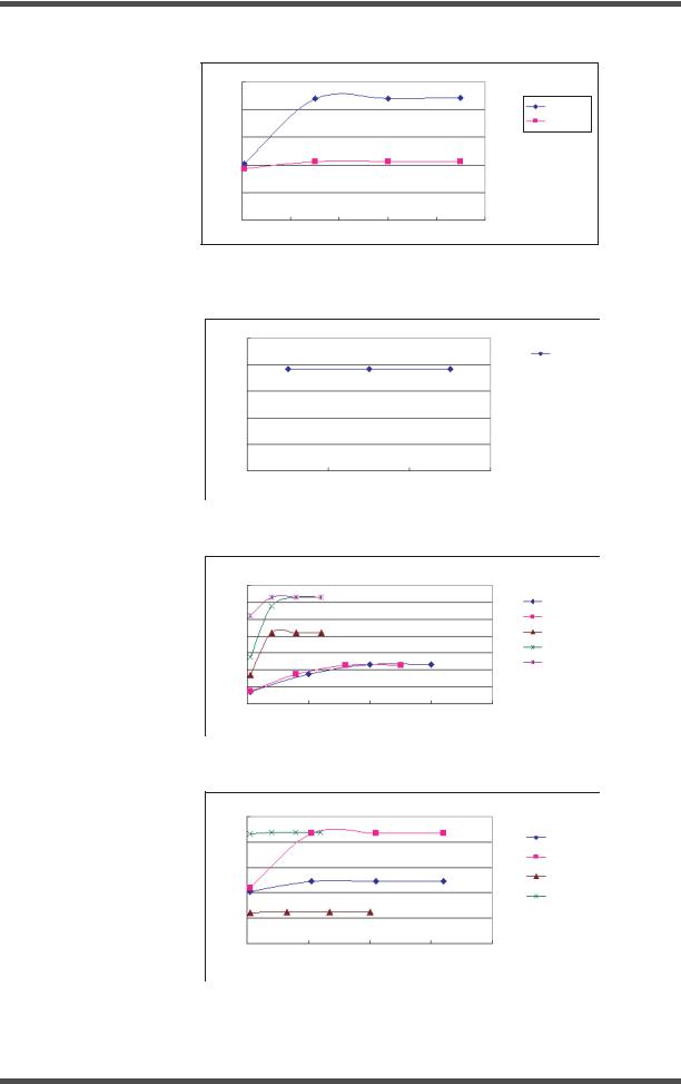
2-1-4 Output characteristics
• Bipolar system
Power (W)
|
|
Bipolar: Maximum setting |
|
|
|
140 |
|
|
|
|
|
120 |
|
|
|
|
|
100 |
|
|
|
|
|
80 |
|
|
|
|
Pure |
|
|
|
|
|
|
60 |
|
|
|
|
Soft 1, Soft 2 |
|
|
|
|
|
|
40 |
|
|
|
|
|
20 |
|
|
|
|
|
0 |
|
|
|
|
|
0 |
500 |
1000 |
1500 |
2000 |
2500 |
|
|
Load resistance ( ) |
|
|
|
|
|
Bipolar: Maximum setting (Hard) |
|
250 |
|
|
200 |
|
(W) |
150 |
L1 |
Power |
100 |
L3 |
|
|
L2 |
50 |
|
|
|
|
|
0 |
|
|
|
|
|
0 |
500 |
1000 |
1500 |
2000 |
2500 |
Load resistance ( )
• Monopolar system
Power (W)
|
|
Monopolar: Maximum setting |
|
||
400 |
|
|
|
|
|
350 |
|
|
|
|
|
300 |
|
|
|
|
Pure/Urology |
250 |
|
|
|
|
|
|
|
|
|
Blend |
|
|
|
|
|
|
|
200 |
|
|
|
|
Coag 1 |
150 |
|
|
|
|
Coag 2 |
|
|
|
|
|
|
100 |
|
|
|
|
Spray |
|
|
|
|
|
|
50 |
|
|
|
|
|
0 |
|
|
|
|
|
0 |
500 |
1000 |
1500 |
2000 |
2500 |
Load resistance ( )
ISSUE4 |
1-3 |
Product Specification |
UES-40
• Saline system
Power (W)
Saline output: Maximum setting
400
350
300
250 |
Pure |
Blend
200
Coag 1
150
Coag 2
100
50
0
0 |
500 |
1000 |
1500 |
2000 |
2500 |
Load resistance ( )
2-1-5 Maximum values
•Bipolar system
Cut: 90 W; Soft 1: 90 W; Soft 2: 90 W; Hard: L3
•Monopolar system
Pure: 300 W; Blend: 250 W; Uro: 300 W; Coag 1: 120 W; Coag 2: 120 W; Spray: 120 W
•Saline system
Pure: 320 W; Blend: 320 W; Coag 1: 200 W; Coag 2: 80 W
2-1-6 Adjustment increments
•Bipolar system
0 to 20 W: 1-W increments; 20 W to 30 W: 2-W increments; 30 W and over: 5-W increments
(Hard is adjustable in 1-level increments.)
•Monopolar system 5-W increments
•Saline system 5-W increments
2-1-7 Control switches
lFoot switch for UES-40 (MAJ-1258)
Controls the high-frequency output of monopolar and bipolar instruments (ON/OFF)
lBipolar foot switch for UES-40 (MAJ-1259)
Controls the high-frequency output of bipolar instruments (ON/OFF)
lHandpiece output switch
Controls the high-frequency output of the handpiece (ON/OFF)
Product Specification |
1-4 |
ISSUE4 |
UES-40
2-1-8 |
Output terminals |
|
|
|
||
|
• Bipolar system |
|
|
|
||
|
Bipolar cord port |
2 ports |
|
|||
|
• Monopolar system |
|
|
|
||
|
Active port |
1 port |
|
|
||
|
Handpiece port |
2 ports |
|
|||
|
• Saline system |
|
|
|
||
|
Dedicated cord port |
1 port |
|
|
||
|
Different control systems are available, depending on the output terminal. The output termi- |
|||||
|
nals and their corresponding controls are listed below. |
|
||||
|
|
|
|
|
|
|
System |
|
Output terminal |
Output |
Control system |
Remarks |
|
|
option |
|||||
|
|
|
|
|
|
|
|
|
|
|
|
|
|
|
|
Bipolar 1 port |
Coag, Cut |
Foot switch for UES-40 |
Bipolar output can be |
|
|
|
selected using the Foot- |
||||
Bipolar |
|
|
|
|
(MAJ-1258) |
switch select switch. |
|
|
|
|
|
||
|
|
|
|
|
|
|
|
|
Bipolar 2 port |
Coag only |
Bipolar foot switch for |
|
|
|
|
UES-40 (MAJ-1259) |
|
|||
|
|
|
|
|
|
|
|
|
|
|
|
|
The saline port detects the |
Saline |
|
Saline port |
Coag, Cut |
MAJ-1258 |
saline cable to be connected |
|
|
and the output terminal is |
|||||
|
|
|
|
|
|
|
|
|
|
|
|
|
automatically selected. |
|
|
|
|
|
|
|
|
|
Handpiece 1 port |
Coag, Cut |
MAJ-1258 |
Monopolar output can be |
|
|
|
handpiece |
selected using the Foot- |
|||
Monopolar |
|
|
|
|
|
switch select switch (except |
|
|
|
|
|
||
|
|
Active port |
Coag, Cut |
MAJ-1258 |
during control using the |
|
|
|
|
|
|
|
handpiece) |
|
|
Handpiece 2 port |
Coag, Cut |
Handpiece |
|
|
|
|
|
|
|
|
|
2-1-9 Recommended timing
Output (ON) timing: within 10 seconds; output stop (OFF): 30 seconds or more
2-2 Safety functions
2-2-1 Patient-plate monitor (for monopolar systems only)
Detects connection problems or disconnection of the single type patient plate, as well as loosening of split type patient plates. If problems are detected, the following operations are performed.
•Warning indicator is lit.
•Error code is displayed on output indicator.
•Audible warning is issued.
•High-frequency output is stopped.
ISSUE4 |
1-5 |
Product Specification |

UES-40
2-2-2 High-frequency-output monitor
Detects whether the output value is correct for the output setting value. If problems are detected, the following operations are performed.
•Error code is displayed on output indicator.
•Audible warning is issued.
•High-frequency output is stopped.
2-2-3 Output timing monitor (for monopolar or saline systems only)
Detects the high-frequency output timing. If output continues for more than 60 seconds, the following operations are performed.
•Error code is displayed on output indicator.
•Audible warning is issued.
•High-frequency output is stopped.
2-2-4 Self-check monitor
Verifies the correct operation of all safety functions. If problems are detected, the following operations are performed.
•Error code is displayed on output indicator.
•Audible warning is issued.
•Various settings are disabled.
•High-frequency output is stopped.
2-2-5 Control switch monitor
Detects short-circuits of each switch (foot switch and handpiece). If problems are detected, the following operations are performed.
•Error code is displayed on output indicator.
•Audible warning is issued.
•Various settings are disabled.
•High-frequency output is stopped.
2-3 Additional features
2-3-1 Preset function
Use of the preset function enables the most-recently used output setting, as well as up to five configurations of preset user settings, to be stored for future use.
2-3-2 CQM function
When split type patient plates are attached, the CQM indicator lights up when there is a good connection with the patient.
Product Specification |
1-6 |
ISSUE4 |

UES-40
2-4 Safety
2-4-1 Medical electrical-equipment classifications
lProtection against electrical shock
Class-I equipment (three-prong plug for power supply)
lLevel of electrical-shock protection
CF-type (low-frequency leakage current of 10µþA or less)
lLevel of explosion protection
Never use the UES-40 where flammable vapors occur.
lOthers
Defibrillator protection
2-5 Laws, regulations, and standards
Region / country |
Applicable laws and regulations / external standards |
|
|
|
MDD |
EU/EFTA |
Classification: IIb |
|
CE marking: CE0197 |
|
|
U.S. |
UL mark |
|
|
Other areas |
None |
|
|
2-6 Others
lDimensions
350 mm (W) ¥ 400 mm (D) ¥ 150 mm (H)
lWeight 12 kg
ISSUE4 |
1-7 |
Product Specification |

UES-40
3.Operating Requirements
(1)The operating conditions must be as follows. Ambient temperature: 10°C to 40°C
Relative humidity: |
30% to 85% |
Atmospheric pressure: |
700 hPa to 1060 hPa |
Never use the UES-40 where flammable vapors occur.
(2) The power requirements are as follows.
Rated input voltage |
120 V |
|
220 V |
|
|
|
|
Rated input current |
12A |
|
6A |
|
|
|
|
Frequency |
|
50/60 Hz |
|
|
|
|
|
Permissible voltage fluctuation |
|
±10% |
|
|
|
|
|
(3)Do not use in combination with products not designated by Olympus.
(4)Before using the UES-40 for the treatment of patients wearing pacemakers, consult the pacemaker manufacturer.
(5)Do not attach the patient plate for use near metallic implants.
(6)Do not wind UES-40 cords into loops or allow them to touch the patient or metallic parts of the surgical table.
(7)Do not bundle UES-40 cords with cords of other medical equipment during use.
(8)Keep the UES-40 and its cords adequately separated from other medical equipment and cords.
(9)If non-CF products are used in combination with the UES-40, do not use directly on the heart.
(10)To ensure electrical safety, use of the following electronic medical equipment in combination with the UES-40 is prohibited:
a)Equipment not yet proven safe when used with the UES-40
b)Equipment not yet proven safe due to certain aspects of operation (such as the leakage current)
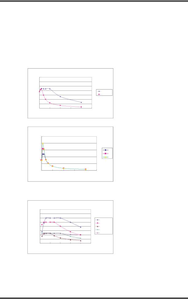
(11)If the UES-40 is used in combination with endoscopic instruments for which the rated voltage is listed in each instrument user manual, compare the open output-voltage characteristics of the instruments with those of the UES-40 and adjust the output within the USE-40’s rated voltage values. Refer to Fig. 1-1 to 1-4 for the open voltage characteristics. If the user’s manuals for these instruments do not list the rated voltage, set the output low initially and then gradually increase the output level.
Product Specification |
1-8 |
ISSUE4 |
UES-40
Maximum output voltage (Vp)
Bipolar: Cut, Soft 1, Soft 2
500
400
300
200
100
0
0 |
20 |
40 |
60 |
80 |
100 |
|
|
Output setting (W) |
|
|
|
Cut
Soft1, Soft2
Figure 1-1 Open voltage characteristics (Bipolar: Pure, Soft 1, Soft 2)
Bipolar: Hard
|
250 |
|
|
|
(Vp) |
|
|
|
Hard |
150 |
|
|
|
|
|
|
|
||
voltage |
200 |
|
|
|
output |
100 |
|
|
|
Maximum |
|
|
|
|
50 |
|
|
|
|
|
|
|
|
|
|
0 |
|
|
|
|
L1 |
L2 |
L3 |
|
|
|
Output setting (W) |
|
|
Figure 1-2 Open voltage characteristics (Bipolar: Hard)
|
|
|
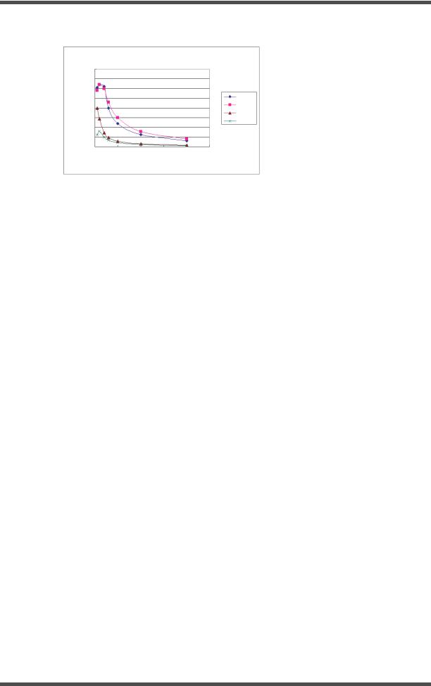
Monopolar |
|
|
|
|
3500 |
|
|
|
|
|
(Vp) |
3000 |
|
|
|
|
|
|
|
|
|
Pure/Urology |
||
|
|
|
|
|
|
|
voltage |
2500 |
|
|
|
|
Blend |
2000 |
|
|
|
|
Coag 1 |
|
output |
|
|
|
|
||
|
|
|
|
|
||
1500 |
|
|
|
|
Coag 2 |
|
|
|
|
|
|
||
|
|
|
|
|
Spray |
|
Maximum |
1000 |
|
|
|
|
|
|
|
|
|
|
||
500 |
|
|
|
|
|
|
|
|
|
|
|
|
|
|
0 |
|
|
|
|
|
|
0 |
100 |
200 |
300 |
400 |
|
Output setting (W)
Figure 1-3 Open voltage characteristics (Monopolar)
|
1000 |
|
Saline |
|
|
|
|
|
|
|
|
|
|
(Vp) |
|
|
|
|
|
|
800 |
|
|
|
|
Pure/Urology |
|
voltage |
|
|
|
|
|
Blend |
600 |
|
|
|
|
|
|
output |
|
|
|
|
|
Coag 1 |
400 |
|
|
|
|
Coag 2 |
|
Maximum |
|
|
|
|
||
|
|
|
|
|
||
200 |
|
|
|
|
|
|
|
|
|
|
|
||
|
|
|
|
|
|
|
|
0 |
|
|
|
|
|
|
0 |
100 |
200 |
300 |
400 |
|
Output setting (W)
Figure 1-4 Open voltage characteristics (Saline)
ISSUE4 |
1-9 |
Product Specification |

UES-40
4. Name and Function of Each Part
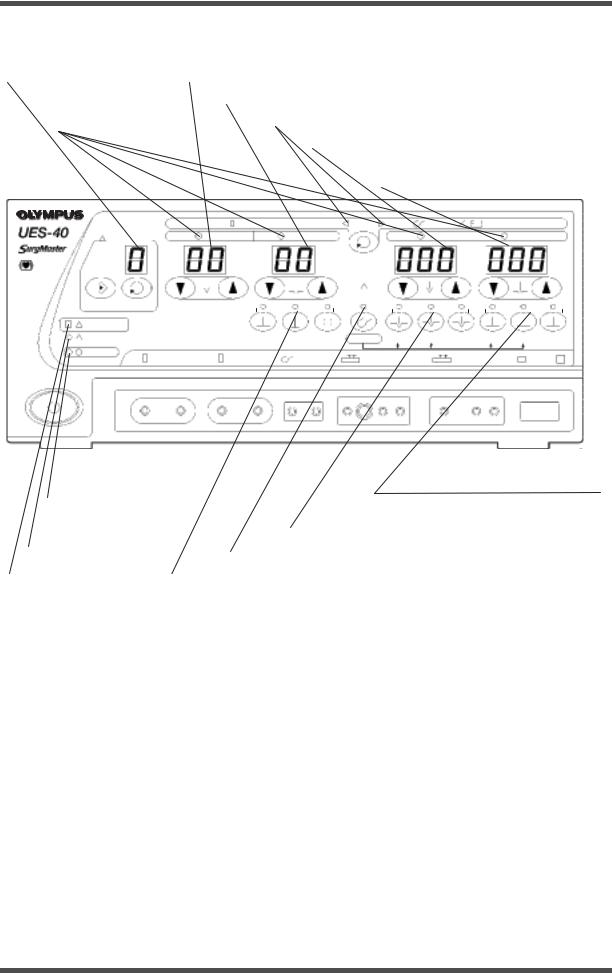
4-1 Front panel (for 120 V and 220 V)
4-1-1 |
Switches and ports |
|
|
|
|
|
|
|
|
|
|
|
|
|
|||
|
|
|
(4) Bipolar coagulation mode |
|
(7) Monopolar/saline cut mode select switch |
||||||||||||
|
|
|
|
select switch |
|
|
|
|
|
|
|
|
|
|
|||
|
|
|
|
|
|
|
|
|
|
|
|
|
|
||||
|
(1) Memory switch |
(5) Saline switch |
|
|
(8) Monopolar/saline coagulation |
||||||||||||
|
|
|
|
|
|
|
|||||||||||
|
|
|
|
|
|
|
|
|
|
|
|
|
|||||
|
|
(2) Select switch |
|
|
(6) Foot switch |
|
|
|
mode select switch |
||||||||
|
|
|
|
|
|
|
|
|
|
|
|||||||
|
|
|
|
|
|
|
|
|
|
|
|
|
|
||||
|
|
|
(3) Output control |
|
|
|
select switch |
|
|
|
|
|
|
|
|||
|
|
|
|
|
|
|
|
|
|
|
|
|
|
|
|
||
|
|
|
|
|
|
|
|
|
|
|
|
|
|
|
|
||
|
|
|
switch |
|
|
|
|
|
|
|
|
|
|
|
|
|
|
|
|
|
|
|
|
BIPOLAR |
|
|
|
SALINE |
MONOPOLAR |
||||||
|
|
|
|
|
|
|
|
|
|||||||||
|
|
|
|
|
|||||||||||||
|
|
|
PRESET |
CUT |
COAG |
|
|
|
CUT |
|
COAG |
||||||
|
|
|
|
|
|
|
|
|
|
|
|
|
|
|
|
||
|
|
|
|
|
|
|
|
|
|
|
FOOT |
|
|
|
|||
|
|
|
|
|
|
W |
|
W |
SWITCH |
W |
W |
||||||
|
|
|
|
|
|
|
SELECT |
||||||||||
|
|
|
|
|
|
|
|
|
|
|
|
|
|
||||
|
|
MEMORY SELECT |
|
|
|
|
|
|
|
|
|
|
|
|
|
||
|
|
|
WARNING |
|
|
|
|
|
|
|
|
|
|
|
|
|
|
|
|
|
COM |
|
SOFT1 |
SOFT2 HARD |
SALINE PURE BLEND |
URO |
COAG.1 COAG.2 SPRAY |
||||||||
|
|
|
POWER |
|
BIPOLAR2 |
SALINE |
|
|
HAND PIECE1 |
HAND PIECE2 PATIENT F |
|||||||
|
|
|
BIPOLAR1 |
|
|
|
|||||||||||
|
|
(12) Active port |
|
(11) Hand piece |
|
(9) Patient plate port |
||
(16) Power switch |
|
port 1 |
|
|||||
|
|
|
|
|
||||
|
|
|
|
|
|
|
||
|
|
|
|
|
|
|
||
|
|
|
|
|
|
|
||
|
(13) Saline port |
|
|
|
(10) Hand piece port 2 |
|||
|
|
|
|
|||||
|
|
|
|
|
|
|||
|
|
|
|
|
|
|
|
|
(14)Bipolar port 2
(15)Bipolar port 1
(1)Memory switch
This switch is used to store output settings and modes that have been previously set.
(2)Select switch
This switch is used to recall stored output settings and modes.
(3)Output control switches
To increase the displayed setting value, press s. To decrease it, press t.
(4)Bipolar coagulation mode select switches
These switches are used to select bipolar coagulation modes.
(5)Saline switch
This switch is used to select the saline mode.
Product Specification |
1-10 |
ISSUE4 |

UES-40
(6)Foot-switch select switch
This switch is used to switch between the saline/monopolar mode and the bipolar output mode.
(7)Monopolar/saline cut mode select switches
These switches are used to select the monopolar and saline cut mode
(8)Monopolar/saline coagulation mode select switches
These switches are used to select the monopolar and saline coagulation mode.
(9)Patient-plate port
This port is used for connection of the patient-plate plug.
(10)Handpiece port 2
This port is used for connection of a monopolar handpiece plug.
(11)Handpiece port 1
This port is used for connection of a monopolar handpiece plug.
(12)Active port
This port is used for the connection of the active electrode of the Active cord.
(13)Saline port
This port is used for connection of the saline code.
(14)Bipolar port 2
This port is used for connection of bipolar electrodes.
(15)Bipolar port 1
This port is used for connection of bipolar electrodes.
(16)Power switch
For turning the power on. When the power is turned on, the power switch indicator lights up.
ISSUE4 |
1-11 |
Product Specification |
UES-40
4-1-2 |
|
Indicators |
|
|
|
|
|
|
|
|
|
|
|
|
|
|
|
|
|
|
|
|
||||
(18) Preset number indicator |
(19) Bipolar cut output setting indicator |
|
|
|
|
|
|
|
||||||||||||||||||
|
|
|
|
|
|
|
|
|
|
|
|
|
|
|
|
|
|
|
|
|
|
|
|
|||
|
|
|
|
|
|
|
|
|
(20) Bipolar coagulation output setting indicator |
|
|
|
|
|||||||||||||
|
|
|
|
|
|
|
|
|
|
|
|
|
|
|
|
|
|
|
|
|
||||||
|
|
|
(17) Output indicators |
|
|
|
|
(21) Foot switch setting indicators |
|
|
|
|
|
|
|
|||||||||||
|
|
|
|
|
|
|
|
|
|
|
|
|
|
|
|
|
|
|
|
|
|
|
||||
|
|
|
|
|
|
|
|
|
|
|
|
|
(22) Monopolar/saline cut output setting indicator |
|||||||||||||
|
|
|
|
|
|
|
|
|
|
|
|
|
||||||||||||||
|
|
|
|
|
|
|
|
|
|
|
|
|
|
|
|
|
|
|
|
|
|
|
|
|||
|
|
|
|
|
|
|
|
|
|
|
|
|
|
|
|
|
(23) Monopolar/saline coagulation |
|||||||||
|
|
|
|
|
|
|
|
|
|
|
|
|
|
|
|
|
|
|
output setting indicator |
|||||||
|
|
|
|
|
|
|
|
|
|
BIPOLAR |
|
|
|
|
|
|
|
|
|
|
|
|
|
|||
|
|
|
|
|
|
|
|
|
|
|
|
|
|
|
|
SALINE |
|
MONOPOLAR |
||||||||
|
|
|
|
|
|
|
|
|
|
|
|
|
|
|
|
|
||||||||||
|
|
|
|
|
|
|
|
|
|
|
|
|||||||||||||||
|
|
|
|
|
PRESET |
|
|
CUT |
COAG |
|
|
|
CUT |
|
|
|
|
COAG |
||||||||
|
|
|
|
|
|
|
|
|
|
|
|
|
|
|
|
|
|
|
|
|
|
|
|
|
||
|
|
|
|
|
|
|
|
|
|
|
|
|
|
|
|
FOOT |
|
|
|
|
|
|
|
|||
|
|
|
|
|
|
|
|
|
|
W |
|
W |
SWITCH |
|
W |
|
W |
|||||||||
|
|
|
|
|
|
|
|
|
|
|
SELECT |
|
|
|||||||||||||
|
|
|
|
|
|
|
|
|
|
|
|
|
|
|
|
|
|
|
|
|
|
|
||||
|
|
|
|
MEMORY SELECT |
|
|
|
|
|
|
|
|
|
|
|
|
|
|
|
|
|
|
|
|
||
|
|
|
|
WARNING |
|
|
|
|
|
|
|
|
|
|
|
|
|
|
|
|
|
|
|
|
||
|
|
|
|
COM |
|
|
|
SOFT1 |
SOFT2 HARD |
SALINE PURE BLEND |
URO |
COAG.1 COAG.2 SPRAY |
||||||||||||||
|
|
|
|
POWER |
|
|
|
BIPOLAR2 |
SALINE |
HAND PIECE1 |
|
HAND PIECE2 PATIENT F |
||||||||||||||
|
|
|
|
|
BIPOLAR1 |
|
|
|||||||||||||||||||
|
|
|
|
|
|
|
|
|
|
(24) Monopolar/saline coagulation |
|
|
|
(28) Power switch indicator |
|
|
|
|
mode indicators |
||||
|
|
|
|
|
|
|
|
||||
|
|
|
|
|
|
|
|
(25) Monopolar/saline cut mode indicators |
|||
|
|
|
|
|
|
|
|
||||
|
(29) CQM indicator |
|
|
|
|
|
|
|
|
|
|
|
|
|
|
|
(26) Saline mode indicator |
||||||
|
|
|
|
|
|
|
|
||||
(30) Warning indicator |
|
|
(27) Bipolar coagulation mode indicators |
|
|||||||
(17)Output indicators
During high-frequency output, the indicator corresponding to the selected output mode (Cut or Coag) lights up.
(18)Preset number indicator
During the use of preset functions, this indicator displays digits from 1 to 5 or P.
(19)Bipolar cut output setting indicator
This indicator displays the value specified using the output control switches.
(20)Bipolar coagulation output setting indicator
This indicator displays the value specified using the output control switches.
(21)Foot-switch setting indicator
This indicator displays the available output from the foot switch for the UES-40 (MAJ-1258).
(22)Monopolar/saline cut output setting indicator
This indicator displays the value specified using the output control switches.
(23)Monopolar/saline coagulation output setting indicator
This indicator displays the value specified using the output control switches.
(24)Monopolar/saline coagulation mode indicators
The lighted indicator corresponds to the coagulation mode selected using the switches.
Product Specification |
1-12 |
ISSUE4 |
UES-40
(25)Monopolar/saline cut mode indicators
The lighted indicator corresponds to the cutting mode selected using the switches.
(26)Saline mode indicator
This indicator lights up when saline mode is selected using the switch.
(27)Bipolar coagulation mode indicators
The lighted indicator corresponds to the coagulation mode selected using the switches.
(28)Power switch indicator
This indicator shows that the power is on after the power switch is activated.
(29)CQM indicator
When split type patient plates are attached, the CQM indicator lights up when there is a good connection with the patient.
(30)Warning indicator
This indicator lights up if equipment problems occur.
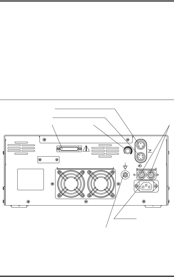
4-2 Rear panel
(4)Foot switch connector for MAJ-1259
(3)Foot switch port for MAJ-1258
(1) System port |
|
(2) Volume knob |
|
(5) Circuit breakers |
SYSTEM |
Foot Switch |
|
MAJ-1259 |
||
|
||
VOLUME |
Foot Switch |
|
MAJ-1258 |
||
|
||
SN |
|
|
|
BREAKERS |
|
12A |
12A |
AC IN
(6) AC inlet
(7) Potential equalization terminal
(1)System port
This system port is for connecting products to expand the functionality of the unit. Connect only Olympus products.
(2)Volume knob
This knob is for adjustment of the sound output.
ISSUE4 |
1-13 |
Product Specification |
UES-40
(3)Foot switch port for MAJ-1258
This port is for connecting the standard accessory foot switch for UES-40.
(4)Foot switch port for MAJ-1259
This port is for connecting an optional bipolar foot switch for UES-40.
(5)Circuit breakers
These breakers are used in the event of mechanical problems to prevent electrical surges within the UES-40.
(6)AC inlet
This inlet is for connecting the power cord.
(7)Potential-equalization terminal
This terminal is connected for potential equalization.
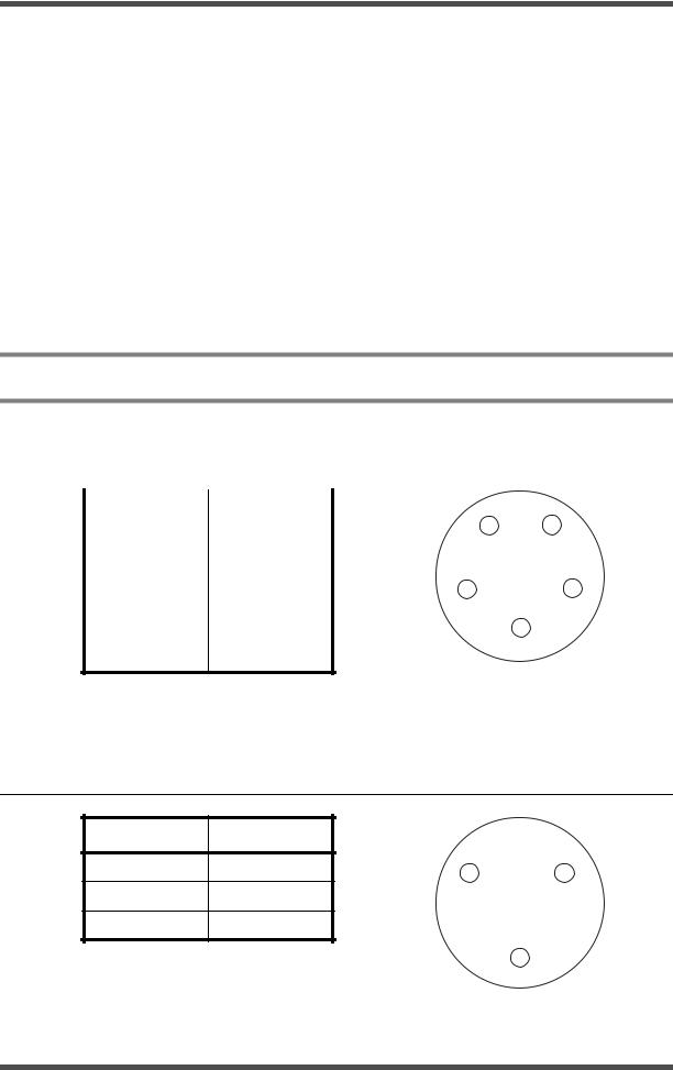
5. Ports
5-1 |
Foot switch port for MAJ-1258 |
|
|
||
|
|
|
|
|
|
|
Pin No. |
Signal |
A |
E |
|
|
|
|
|
||
|
A |
FS1CUT1 |
|||
|
|
|
|||
|
|
|
|
|
|
|
B |
TS1COAG1 |
|
|
|
|
|
|
|
B |
D |
|
C |
FS1PA1 |
|||
|
|
|
|||
|
|
|
|
|
|
|
D |
GND |
|
C |
|
|
|
|
|
|
|
|
E |
FS/MODE |
|
|
|
As viewed from the connection side
5-2 Bipoler foot switch port for MAJ-1259
Pin No. |
Signal |
|
|
A |
FS3COAG1 |
A |
C |
|
|
||
B |
GND |
|
|
C |
NC |
|
|
B
As viewed from the connection side
Product Specification |
1-14 |
ISSUE4 |
 Loading...