


Modules described in this manual
SZ2-ST
WHSZ Series Eyepieces
Objectives
SZX-EPA
SZX-AS
SZX-STAD1
SZH-STAD1
SZ2-FO
SZH-SG
SZH-SC INSTRUCTIONS
SZX7
STEREOMICROSCOPE SYSTEM
This instruction manual is for the Olympus stereomicroscope system. To ensure the safety, obtain optimum performance and to familiarize yourself fully with the use of this microscope, we recommend that you study this manual thoroughly before operating the microscope.
Retain this instruction manual in an easily accessible place near the work desk for future reference.
A X 6 6 3 1

SZX7
CONTENTS
Correct assembly and adjustments are critical for the microscope to manifest its full performance. If you are going to assemble the microscope by yourself, please read Chapter 8, “ASSEMBLY” (pages 16 to 18). For the assemblies of the modules for which instruction manuals are available, refer to their instruction manuals.
IMPORTANT — Be sure to read this chapter for safe use of the equipment. — 1-2
1 NOMENCLATURE
2CONTROLS
3 OBSERVATION PROCEDURE
4OPERATION
3
4
5
6-12
4-1 |
Stand......................................................................................................................................................................................................................... |
|
6 |
|
|
1 |
Using the Stage |
2 |
Adjusting the Focus Adjustment Knob Tension |
4-2 |
Observation Tube............................................................................................................................................................................ |
|
6-9 |
|
|
1 |
Adjusting the Interpupillary Distance |
2 |
Adjusting the Diopter (Zoom Confocality Adjustment) |
|
3 |
Using the Eye Shades |
4 |
Using an Eyepiece Micrometer Disk |
|
5 |
Selecting the Light Path (SZX-TR30) |
6 |
Adjusting the Tilt (SZX-TBI) |
4-3 |
Microscope Body ...................................................................................................................................................................... |
|
10-11 |
|
|
1 |
Zoom Magnification Indication |
2 |
Switching the Click Stop ON-OFF |
|
3 |
Using Auxiliary Sleeve SZ2-ET |
|
|
4-4 |
TV Observation and Photomicrography |
.............................................................................................................. 12 |
||
5TROUBLESHOOTING GUIDE
6SPECIFICATIONS
7 OPTICAL PERFORMANCE
8ASSEMBLY
9OPTIONAL MODULES
13
14
15
16-18
19-27
SZX-EPA, SZX-AS, SZX-STAD1, SZH-STAD1, SZ2-FO, SZH-SG, SZH-SC
IMPORTANT
The SZX7 stereomicroscope is provided with the ESD (Electro-Static Discharge) protection specifications. It is provided with electroconductive coating in the external finish to reduce the surface resistance and grounding lead wires in their standard stand or system to eliminate static electricity from them.
CAUTION To maintain the ESD protection performance, always use the microscope in combination with the modules described in this manual or options having the ESD protection specifications. Otherwise, the grounding will not work properly.
 SAFETY PRECAUTIONS
1.After the equipment has been used in an observation of a specimen that is accompanied with a potential of infection, clean the parts coming in contact with the specimen to prevent infection.
·Moving this microscope is accompanied with the risk of
dropping the specimen. Be sure to remove the specimen before moving this product.
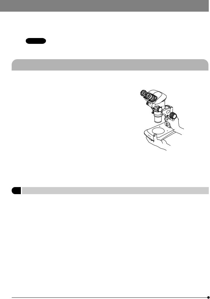
· Hold the bottom of the stand with one hand while holding base column with the other hand to avoid tilting the microscope.
· In case the specimen is damaged by erroneous operation, promptly take the infection prevention measures.
2.The desktop should be a level surface with an inclination of less than 3°, and the load to the microscope should be less than 7 kg (when the SZ2-ST standard stand is used).
The microscope may become unstable when certain intermediate attachment and/or photography unit are mounted on it. Be careful so that the microscope does not topple down.
3.When the microscope is to be disposed of, follow your local industrial waste disposal regulations. If you have any questions, please contact Olympus.
1 Getting Ready
1.A microscope is a precision instrument. Handle it with care and avoid subjecting it to sudden or severe impact.
2.Do not use the microscope where it is subjected to direct sunlight, high temperature and humidity, dust or vibrations. (For the operating conditions, see Chapter 6, “SPECIFICATIONS” on page 14.)
3.Do not turn the zoom adjustment knobs beyond the stopper positions. Otherwise, the internal mechanism may be damaged.
Do not turn the left and right zoom adjustment knobs in the opposite directions, as this will result in a failure.
4.Only one intermediate attachment having thickness up to 60 mm can be mounted on the microscope. If two intermedi-
ate attachments or an intermediate attachment thicker than 60 mm is mounted, the image may be cut a little. However, the coaxial reflected light illuminator (SZX-ILLC) is not counted in the number of intermediate attachment.
}When using multiple modules, they should be stacked in order of the SZX-ILLC, SZX-AS, SZX-RFA (SZX-RFL), SZX-SDO, SZX-APT, SZX-BS, SZX-DA, SZX-FAD and SZX-EPA from the bottom to the top.
1

SZX7
2Maintenance and Storage
1.To clean the lenses and other glass components, simply blow dirty away using a commercially available blower and wipe gently using a piece of cleaning paper (or clean gauze).
If a lens is stained with fingerprints or oil smudges, wipe it gauze slightly moistened with commercially available absolute
alcohol.
 Since the absolute alcohol is highly flammable, it must be handled carefully.
Be sure to keep it away from open flames or potential sources of electrical sparks –– for example, electrical equipment that is being switched on or off.
Also remember to always use it only in a well-ventilated room.
2.Do not attempt to use organic solvents to clean the microscope components other than the glass components because they use plastic resin materials extensively. To clean them, use a lint-free, soft cloth slightly moistened with a diluted neutral detergent.
3.Do not disassemble any part of the microscope as this could result in malfunction or reduced performance.
4.When disposing of the microscope. Check the regulations and rules of your local government and be sure to observe them.
3Caution
If the microscope is used in a manner not specified by this manual, the safety of the user may be imperiled. In addition, the equipment may also be damaged. Always use the equipment as outlined in this instruction manual.
The following symbols are used to set off text in this instruction manual.
 : Indicates that failure to follow the instructions in the warning could result in bodily harm to the user and/or damage to equipment (including objects in the vicinity of the equipment).
# : Indicates that failure to follow the instructions could result in damage to equipment. } : Indicates commentary (for ease of operation and maintenance).
4Intended use
This instrument has been designed to be used to observe magnified images of specimens in routine and research applications.
Do not use this instrument for any purpose other than its intended use.
This device complies with the requirements of directive 98/79/EC concerning in vitro diagnostic medical devices. CE marking means the conformity to the directive.
NOTE: This equipment has been tested and found to comply with the limits for a Class A digital device,
pursuant to Part 15 of the FCC Rules. These limits are designed to provide reasonable protection
against harmful interference when the equipment is operated in a commercial environment. This
equipment generates, uses, and can radiate radio frequency energy and, if not installed and used in
accordance with the instruction manual, may cause harmful interference to radio communications.
Operation of this equipment in a residential area is likely to cause harmful interference in which case
the user will be required to correct the interference at his own expense.
FCC WARNING: Changes or modifications not expressly approved by the party responsible for compliance
could void the user’s authority to operate the equipment.
2

NOMENCLATURE
*Modules marked * are given the ESD specifications.
(Note) The modules shown in the following diagram are merely the typical examples. For the modules that are not shown below, please consult Olympus or the latest catalogues.
Eyepiece
·WHSZ10X*
·WHSZ10X-H*
·WHSZ15X-H*
·WHSZ20X*
· WHSZ20X-H* · WHSZ30X-H*
Microscope Body
· 7X Zooming Microscope Body: SZX-ZB7*
Objective
·DFPL0.5X-4*
·DFPL0.75X-4*
·DFPLAPO1X-4*
·SZX-ACH1X*
·SZX-ACH1.25X*
·DFPL1.5X-4*
· DFPL2X-4*
Observation Tube
·Binocular Tube: SZX-BI45*
·Binocular Tube: SZX-BI30
·Trinocular Tube: SZX-TR30
·Tilting Tube: SZX-TBI
Intermediate Attachment
·AS Unit: SZX-AS
·Eye Point Adjuster: SZX-EPA
·Coaxial Reflected Light Illuminator: SZX-ILLC
Stand Note 1)
· Standard Stand: SZ2-ST*
· LED Illuminator Stand: SZ2-ILST
Stage Plate
·Black/White: SZ2-SPBW*
(ESD protection on black surface)
·Transparent: SP-C
·Other stage adapter
Auxiliary Sleeve
· SZ2-ET*
Note 1) The microscope can also be mounted on the SZ2-STU1/STU2/STU3 large stand as well as on the SZX-ST SZX standard stand by using the SZ2-STB1/SZ2-STS focusing arm.
3

SZX7
CONTROLS
Eye shades (Page 8)
Eyepiece clamping knobs
Body clamping knob
Threaded for accessory mounting
Accessory mounting screws (x 5)
Stage plate
Allen screwdriver
Stage adapter mounting screws
M4 screws (x 2)
Zoom magnification indication (Page 10) Indicates 0.8, 1, 1.25, 1.6, 2, 2.5, 3.2, 4, 5 and 5.6
Click stop ON-OFF screw (Page 10)
Zoom adjustment knobs (Page 7) 0.8X to 5.6X
Focus adjustment knob (Page 6)
Stroke: 120 mm
Accessory mounting holes
Diameter  4 mm (x 2)
Allen screwdriver holder (Page 16)
With double-side adhesive tape.
Grounding holes (Page 16)
For  4 mm banana plugs (x 4)
4
OBSERVATION PROCEDURE
}If you have not assembled the microscope yet, please read Chapter 8, “ASSEMBLY” (pages 16 to 18).
3-1 Preparation
|
|
|
(Page) |
|
1. |
Confirm the mounting, particularly that of the observation tube.................................................................................................................... |
(P. 16 - 18) |
||
2. |
Adjust the rotation tension of the focus adjustment knob. |
................................................................................................................................................... |
(P. 6) |
|
|
|
|||
3. |
Prepare the light source as required. |
|
|
|
3-2 Procedure
1. Place the specimen on the stage. (Page 6)
2. Adjust the interpupillary distance. (Page 6)
3. Adjust the eyepiece diopter. (Page 7)
· The adjustment operation is variable whether the eyepieces use an eyepiece micrometer disk or not.
|
4. Set the zoom adjustment knob @ for the lowest magnification and rotate |
|
1 |
the focus adjustment knob ² to bring the specimen into approximate |
|
focus. |
||
|
||
|
² |
|
|
5. Rotate the zoom adjustment knob @ to the target magnification and |
|
|
rotate the focus adjustment knob ² to bring the specimen into accurate |
|
|
focus. |
}When the optional AS unit (SZX-AS) is used, the contrast of image and the focal depth of specimen can be adjusted with the aperture iris diaphragm lever.
5

SZX7
OPERATION
4-1 Stand
1Using the Stage
1.When reflected light illumination is used, the stage plate can be placed either the white or black surface facing up depending on the specimen. However, when the ESD performance is required, always use the black surface of the stage plate.
2.When transmitted light illumination is used, use the transparent glass stage plate (SP-C).
2 Adjusting the Focus Adjustment Knob Tension (Fig. 1)
To decrease
}This operation is intended to facilitate the rotation of the knobs while preventing spontaneous drop of the microscope body. It is recommended
Clamp.
to set the knob tension to a slightly higher level than the point where
To increase
spontaneous drop occurs.
1.Hold the left and right focus adjustment knobs @ with both hands, fix the left knob and rotate the right knob. The rotation tension of the knobs
1 |
increases or decreases according to the direction in which the right knob |
|
|
is rotated. |
|
Fig. 1 |
2. If the rotation tension is increased too much, accurate focusing is not |
|
possible and the mechanism may be damaged. |
||
|
4-2 Observation Tube
1 |
1 |
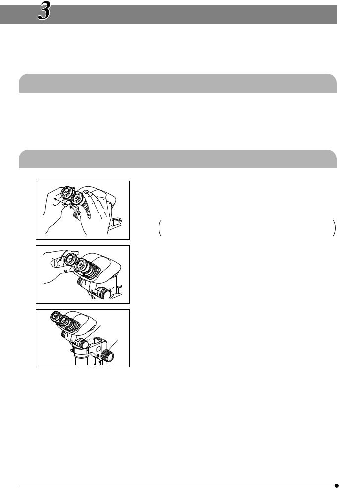
Adjusting the Interpupillary Distance |
(Fig. 2) |
#Always hold the eyepiece sleeves @ with both hands when adjusting the interpupillary distance.
While holding the left and right eyepiece sleeves @ with both hands, look through the eyepieces and adjust for binocular vision until the left and right fields of view coincide completely.
Fig. 2
6
|
2 |
Adjusting the Diopter (Zoom Confocality Adjustment) (Fig. 3) |
||
|
³ |
#Confirm that the eyepiece clamping knobs @ are tightened firmly |
||
|
|
before proceeding to the adjustment. |
||
² |
|
|
||
|
Eyepieces without eyepiece micrometer disk |
|||
|
| |
|||
1 |
1. |
Turn the diopter adjustment rings ² of the left and right eyepieces to |
||
|
||||
|
|
|
positions “0”. (This adjustment is not possible with eyepieces without |
|
|
|
|
helicoids.) |
|
|
|
2. |
Place an easy-to-observe specimen on the stage plate. |
|
|
Fig. 3 |
3. |
Set the zoom adjustment knob ³ for the lowest magnification and rotate |
|
|
|
the focus adjustment knob | to bring the specimen into focus. |
||
|
|
|
||
4.Set the zoom adjustment knob ³ for the highest magnification and rotate the focus adjustment knob | to bring the specimen into focus.
5.Set the zoom adjustment knob ³ for the lowest magnification and rotate the diopter adjustment rings ² of the left and right eyepieces, instead of
the focus adjustment knob, to bring the specimen into focus.
}Set the zoom adjustment knob ³ for the highest magnification again and check the image focusing. The diopter adjustment is complete if the image in accurate focus. If not, repeat steps 3 to 5 above.
Eyepieces with eyepiece micrometer disk
1.Look through the eyepiece with eyepiece micrometer disk and rotate its diopter adjustment ring ² to bring the micrometer scale into focus.
2.Place an easy-to-observe specimen on the stage plate.
3.Set the zoom adjustment knob ³ for low magnification, look through the eyepiece with eyepiece micrometer disk and rotate the focus adjustment knob | to bring the specimen into focus.
4.Set the zoom adjustment knob ³ for the highest magnification, look through the eyepiece with micrometer disk and rotate the focus adjustment knob | to bring the specimen into focus.
5.Set the zoom adjustment knob ³ for the lowest magnification and rotate the diopter adjustment ring of the eyepiece without eyepiece micrometer disk, instead of the focus adjustment knob, to bring the specimen into
focus.
}Set the zoom adjustment knob ³ for the highest magnification again and check the image focusing. The diopter adjustment is complete if the image in accurate focus. If not, repeat steps 3 to 5 above.
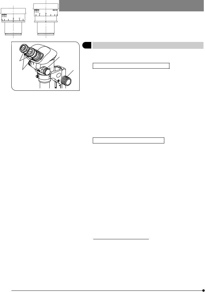
}Note the left and right diopter scale values so that it can be quickly duplicated in future observations.
Diopter scale of the 10X eyepieces
}The valid range of the diopter scale is between -8 and +5 but a slight margin is added to it. Therefore, the diopter value may exceed +5 or -8 when it is adjusted to the maximum. In this case, whether the diopter value is over +8 or under -5 can be identified by the length of the eyepiece.
- 8 |
|
+ 5 |
7
 Loading...