


MAINTENANCE & REPAIR MANUAL
WM--P1 SERIES MOBILE WORKSTATIONS
WM--NP1
WM--WP1
WM--DP1
OLYMPUS MEDICAL SYSTEMS CORP.
2951 Ishikawa-cho, Hachioji-shi, Tokyo 192-8507, Japan
Fax: (042) 646-2429 Telephone: (042) 642-2111
OLYMPUS EUROPA HOLDING GMBH
(Premises/Goods delivery) Wendenstrasse 14-18, 20097 Hamburg, Germany (Letters) Postfach 10 49 08, 20034 Hamburg, Germany
Fax: (040)23773-4656 Telephone: (040)23773-0
OLYMPUS AMERICA INC.
3500 Corporate Parkway, P.O. Box 610, Center Valley, PA
18034-0610, U.S.A.
Fax: (484) 896-7128 Telephone: (484) 896-5000
 KEYMED LTD.
KeyMed House, Stock Road, Southend-on-Sea, Essex SS2 5QH, United Kingdom
Fax: (01702) 465677 Telephone: (01702) 616333
OLYMPUS SINGAPORE PTE LTD.
491B, River Valley Road #12-01/04, Valley Point Office Tower, Singapore 248373
Fax: 6834-2438 Telephone: 6834-0010
OLYMPUS (BEIJING) SALES & SERVICE CO,. LTD.
A8F, Ping An International Financial Center, No. 1-3, Xinyuan South Road,
Chaoyang District, Beijing, 100027 P.R.C.
Fax: (86)10-5976-1299 Telephone: (86)10-5819-9000
OLYMPUS MOSCOW LIMITED LIABILITY COMPANY
117071, Moscow, Malaya Kaluzhskaya 19, bld. 1, fl.2, Russia Fax: (095) 958-2277 Telephone: (095) 958-2245
OLYMPUS AUSTRALIA PTY. LTD.
31 Gilby Road, Mount Waverley, VIC., 3149, Australia
Fax: (03)9543-1350 Telephone: (03)9265-5400
OLYMPUS LATIN AMERICA INC.
5301 Blue Lagoon Drive, Suite 290 Miami, FL 33126-2097, U.S.A.
Fax: (305)261-4421 Telephone: (305)266-2332
OLYMPUS KOREA CO,. LTD.
Olympus-Tower, 114-9 Samseong-Dong, Gangnam-Gu, Seoul 135-090 Korea
Fax: (02)6255-3494 Telephone: (02)6255-3210
Issue 20 |
EKeyMed 2012 |
July 2012 |
K 5070557 |

MAINTENANCE & REPAIR MANUAL
M- NP1 / WMWP1 / WMDP1 WORKSTATIONS
CHANGE OF ISSUE LOG
When an up--issued copy of this manual is received, record its receipt on this page.
A brief description of the change can be found on the last page of the manual : Summary of Change History. Changes made to the current issue are highlighted in the manual by a vertical line in the right hand margin.
Each up--issued copy of the manual will include an up--issued copy of this page but it does not have to be retained unless needed as a continuation sheet.
|
Date |
Issue |
Signature |
Date |
Issue |
Signature |
|
|
|
number of |
|
|
number of |
|
|
|
|
manual |
|
|
manual |
|
|
|
|
|
|
|
|
|
|
|
|
|
|
|
|
|
|
|
|
|
|
|
|
|
|
|
Page 2 of 76 |
WM--P1 SERIES WORKSTATIONS |
Issue 20 : July 2012 |

MAINTENANCE & REPAIR MANUAL
WMNP1 / WMWP1 WMDP1
Manual Contents
|
|
Page |
Preliminary Material |
|
|
Title Page |
. . . . . . . . . . . . . . . . . . . . . . . . . . . . . . . . . . . . . . . . . . . . . . . . . . . . . . . . . . . . . . . |
. . . 1 |
Change of |
issue log . . . . . . . . . . . . . . . . . . . . . . . . . . . . . . . . . . . . . . . . . . . . . . . . . . . . . . . . |
. . . 2 |
Manual Contents (this page) . . . . . . . . . . . . . . . . . . . . . . . . . . . . . . . . . . . . . . . . . . . . . . . . . . |
. . . 3 |
|
Chapters |
|
|
1 |
Introduction . . . . . . . . . . . . . . . . . . . . . . . . . . . . . . . . . . . . . . . . . . . . . . . . . . . . . . |
. . . 4 |
2 |
General Information . . . . . . . . . . . . . . . . . . . . . . . . . . . . . . . . . . . . . . . . . . . . . . . . |
. . . 6 |
3 |
Specifications . . . . . . . . . . . . . . . . . . . . . . . . . . . . . . . . . . . . . . . . . . . . . . . . . . . . |
. . . 8 |
4 |
Tools & Test Equipment . . . . . . . . . . . . . . . . . . . . . . . . . . . . . . . . . . . . . . . . . . . . . |
. . 12 |
5 |
Test and Inspection . . . . . . . . . . . . . . . . . . . . . . . . . . . . . . . . . . . . . . . . . . . . . . . . |
. . 14 |
6 |
Part Replacement . . . . . . . . . . . . . . . . . . . . . . . . . . . . . . . . . . . . . . . . . . . . . . . . . |
. . 16 |
7 |
Illustrated Parts List . . . . . . . . . . . . . . . . . . . . . . . . . . . . . . . . . . . . . . . . . . . . . . . . |
. . 27 |
8 |
Accessories Illustrated Parts List . . . . . . . . . . . . . . . . . . . . . . . . . . . . . . . . . . . . . . . |
. . 39 |
|
Summary of Change History . . . . . . . . . . . . . . . . . . . . . . . . . . . . . . . . . . . . . . . . . . |
. . 76 |
|
Page 3 of 76 |
WM--P1 SERIES WORKSTATIONS |
Issue 20 : July 2012 |

Chapter 1 Introduction
Table of Contents
Page
Introduction . . . . . . . . . . . . . . . . . . . . . . . . . . . . . . . . . . . . . . . . . . . . . . . . . . . . . . . . . 5
|
Page 4 of 76 |
WM--P1 SERIES WORKSTATIONS |
Issue 20 : July 2012 |

1 INTRODUCTION
This Maintenance and Repair Manual has been produced by KeyMed to enable the repair and servicing of the Olympus WM--P1 series mobile workstation.
Although every effort has been made to ensure that this document is correct and complete, KeyMed cannot be held responsible for the safety or reliability of any equipment which has been repaired other than by suitably qualified personnel. It is essential that this manual is read and understood before commencing any work.
Should any additional information or advice be required, please contact:
Olympus KeyMed
Technical Services
Technical Support
KeyMed House
Stock Road
SOUTHEND--ON--SEA
Essex SS2 5QH
United Kingdom
Tel: (01702) 616333
Fax: (01702) 465677
Telex: 995283
|
Page 5 of 76 |
WM--P1 SERIES WORKSTATIONS |
Issue 20 : July 2012 |

Chapter 2 General Information
Table of Contents
Page
General information . . . . . . . . . . . . . . . . . . . . . . . . . . . . . . . . . . . . . . . . . . . . . . . . . . . |
7 |
|
Page 6 of 76 |
WM--P1 SERIES WORKSTATIONS |
Issue 20 : July 2012 |

2 GENERAL INFORMATION
The Olympus WM--P1 series mobile workstation is intended for use in medical facilities under the direction of a trained physician, and has been designed to accommodate the Olympus video system center and associated ancillary devices as a practical mobile workstation to facilitate GI endoscopy, endoscopic ultrasound, respiratory and surgical endoscopic procedures.
Olympus will not be responsible for damage or injury to equipment or personnel, caused by unauthorised modification or repair to this unit.
Maintenance
In the interest of safety and good maintenance, ensure that all fixings are secure. It is recommended that the security fixing torques of the monitor platform, shelf’s, castors and side column fixings specified in the illustrated parts list, are checked every six months.
|
Page 7 of 76 |
WM--P1 SERIES WORKSTATIONS |
Issue 20 : July 2012 |

Chapter 3 Specifications
Table of Contents
|
|
Page |
3.1 |
WM--NP1 / WM--WP1 series mobile workstations . . . . . . . . . . . . . . . . . . . . . . . . . . . . |
. . 9 |
3.2 |
WM--DP1 series mobile workstations . . . . . . . . . . . . . . . . . . . . . . . . . . . . . . . . . . . . . . |
10 |
3.3 |
WM--T1 series separation transformers . . . . . . . . . . . . . . . . . . . . . . . . . . . . . . . . . . . . |
10 |
|
Page 8 of 76 |
WM--P1 SERIES WORKSTATIONS |
Issue 20 : July 2012 |

3 SPECIFICATIONS
3.1WMNP1 / WMWP1 series mobile workstations
Product name |
WM--NP1 / WM--WP1 mobile workstation |
||
|
|
|
|
Dimensions (mm) |
Height: |
1370 (scope in lowest position) |
|
|
|
2140 (scope in highest position) |
|
|
|
1160 (to top tray) |
|
|
|
1826 max (with 19” LCD monitor in highest position) |
|
|
Depth: |
650 |
|
|
Width: |
645 (WM--NP1) 795 (WM--WP1) |
|
|
|
||
Weight |
85kg (WM--NP1) 90kg (WM--WP1) unladen, including fitted transformer. |
||
|
|
|
|
Load capacity |
Top tray |
20kg |
|
(evenly distributed) |
Intermediate shelves 31kg each |
|
|
|
Base panel |
31kg |
|
|
NOTE: Equipment stored on the mobile workstation should not exceed |
||
|
the size of the shelf. |
|
|
|
|
||
Castors |
4 x 125mm non--antistatic, two with brakes.* |
||
|
|
|
|
Ambient temperature |
Storage: |
--40 C to |
+70 C |
(--40 F to +158 F) |
Operation: |
10 -- 40 C (50 -- 104 F) |
|
|
|
|
|
Relative humidity |
95% maximum @ 40 C (104 F) non--condensing |
||
|
|
|
|
Atmospheric pressure |
Storage: |
23.5--106 kPa (3.4--15.37lbf/in2) |
|
|
Operation: |
70--106 kPa (10.15--15.37lbf/in 2) |
|
* UK workstations fitted with Antistatic castors from Oct 2007.
|
Page 9 of 76 |
WM--P1 SERIES WORKSTATIONS |
Issue 20 : July 2012 |

3.2WMDP1 series mobile workstations
|
Product name |
WM--DP1 mobile workstation |
|
|
|
|
|
|
|
|
|
|
Dimensions (mm) |
Height: |
1370 (scope in lowest position) |
|
|
|
|
|
2140 (scope in highest position) |
|
|
|
|
|
1160 (to top tray) |
|
|
|
|
|
1826 max (with 19” LCD monitor in highest position) |
|
|
|
|
Depth: |
655 |
|
|
|
|
Width: |
1100 |
|
|
|
|
|
|
||
|
Weight |
120kg unladen, including fitted transformer. |
|
||
|
|
|
|
|
|
|
Load capacity |
Top tray |
10kg |
|
|
|
(evenly distributed) |
Intermediate shelves 26kg each |
|
|
|
|
|
Base panel |
45kg |
|
|
|
|
NOTE: Equipment stored on the mobile workstation should not exceed |
|
||
|
|
the size of the shelf. |
|
|
|
|
|
|
|
||
|
Castors |
4 x 125mm non--antistatic, two with brakes.* |
|
||
|
|
|
|
|
|
|
Ambient temperature |
Storage: |
--40 C to |
+70 C |
|
|
(--40 F to +158 F) |
Operation: |
10 -- 40 C (50 -- 104 F) |
|
|
|
|
|
|
|
|
|
Relative humidity |
95% maximum @ 40 C (104 F) non--condensing |
|
||
|
|
|
|
|
|
|
Atmospheric pressure |
Storage: |
23.5--106 kPa (3.4--15.37lbf/in2) |
|
|
|
|
Operation: |
70--106 kPa (10.15--15.37lbf/in 2) |
|
|
* UK workstations fitted with Antistatic castors from Oct 2007.
3.3WMT1 series separation transformers
Product name |
Olympus Separation Transformer |
|
|
||
|
|
|
|
|
|
Identification |
Market |
Japan |
USA |
UK, Europe, |
|
|
|
|
|
Rest of the world |
|
|
|
|
|
|
|
|
Model No. |
MAJ--173 |
MAJ--174 |
MAJ--175 |
|
|
|
|
|
|
|
|
Part No. |
K10000289 |
K10000290 |
K10000291 |
|
|
|
|
|
|
|
Power input |
Input voltage |
100V |
110--120V |
220--240V |
|
requirements |
|
|
|
|
|
Frequency |
50/60Hz |
60Hz |
50/60Hz |
||
|
|||||
|
|
|
|
|
|
|
Power input (max) |
1350VA |
1300VA |
1900VA |
|
|
|
|
|
|
|
|
Power cable part No. |
K10001001 |
K10001002 |
K10001003 (UK) |
|
|
|
|
|
K10001004 (Europe) |
|
|
|
|
|
K10001005 (RoW) |
|
|
|
|
|
|
|
Power output |
Maximum load |
1250VA * |
1250VA |
1800VA |
|
|
|
|
|
|
|
|
|
* Maximum 10A load per IEC socket outlet (MAJ--173 only) |
|||
|
|
|
|
|
|
Overload |
Input circuit breakers |
2 x 15A |
2 x 13A |
2 x 9A |
|
protection |
|
|
|
|
|
Output fuse |
T15AH |
T15AH |
T10AH |
||
|
|||||
|
|
|
|
|
|
|
Page 10 of 76 |
WM--P1 SERIES WORKSTATIONS |
Issue 20 : July 2012 |
Potential |
Terminals fitted |
2 at input, 2 x 6 at output |
||
equalisation |
|
|
|
|
|
|
|
|
|
|
|
The Separation Transformer conforms to the relevant |
||
|
Standards compliance |
requirements of |
||
|
EN IEC 60601--1/EN IEC 60601--1--1:2001, Annex EEE/UL |
|||
|
|
|||
|
|
60601--1 and CAN/CSA Std. No. C22.2 No. 601.1--M90 |
||
|
|
|
|
|
|
Type of protection against electric |
Class I equipment. |
||
Classification |
shock. |
|
|
|
|
|
|
||
|
Degree of protection against |
NONE -- The Separation transformer should not be used |
||
|
explosion |
within the zone of risk of flammable gases |
||
|
|
|
|
|
|
Degree of protection against ingress |
IPXO as defined in EN IEC 60529:1992, ordinary equipment. |
||
|
of water. |
|||
|
|
|
||
|
|
|
|
|
|
Mode of operation |
Continuous |
||
|
|
|
|
|
|
Ambient temperature |
Storage: --40 C to 70 C (--40 F to 158 F) |
||
|
|
|
||
Environmental |
Operation: 10 C to 40 C (50 F to 104 F) |
|||
|
||||
|
|
|
||
conditions |
Atmospheric pressure |
Storage/Operation: 70--106 kPa (10.3--15.4lbf/in2) |
||
|
|
|
|
|
|
Relative humidity |
95% maximum @ 40 C (104 F) non--condensing |
||
|
|
|
220--240V units are CE marked in |
|
|
|
|
||
|
|
|
accordance with Directive 93/42/EEC of |
|
Regulatory status |
|
|
14 June 1993 concerning medical |
|
|
|
devices, as an accessory to a medical |
||
|
|
|
||
|
|
|
device, Class I. Year of manufacture is |
|
|
|
|
given in first two digits of serial number. |
|
|
European Economic Area (EEA) |
|
In accordance with European Directive |
|
|
|
|||
|
|
2002/96/EC on Waste Electrical and |
||
|
|
|
Electronic Equipment, this symbol |
|
End of Life |
|
|
indicates that the product must not be |
|
|
|
disposed of as unsorted municipal waste, |
||
|
|
|
but should be collected separately. Refer |
|
|
|
|
to your local Olympus distributor for return |
|
|
|
|
and/or collection systems available in your |
|
|
|
|
country. |
|
|
|
|
|
|
The Olympus WM--P1 series Mobile Workstation and Separation Transformer is manufactured in the
UK by KeyMed (Medical & Industrial Equipment) Ltd.
|
Page 11 of 76 |
WM--P1 SERIES WORKSTATIONS |
Issue 20 : July 2012 |

Chapter 4 Tools & Test Equipment
Table of Contents
4.1 |
Standard Tools and Test equipment required . . . . . . . . . . . . . . . . . . . . . . . . . . . . . . . . |
13 |
4.2 |
Specialised tools required . . . . . . . . . . . . . . . . . . . . . . . . . . . . . . . . . . . . . . . . . . . . . . |
13 |
4.3 |
Consumables . . . . . . . . . . . . . . . . . . . . . . . . . . . . . . . . . . . . . . . . . . . . . . . . . . . . . . |
13 |
|
Page 12 of 76 |
WM--P1 SERIES WORKSTATIONS |
Issue 20 : July 2012 |

4 |
TOOLS & TEST EQUIPMENT |
|
||
4.1 |
Standard Tools required |
|
||
|
Flat blade screwdriver |
Torque driver |
||
|
No 2 Pozidrive tool bit |
No 3 Pozidrive tool bit |
||
|
4mm Hex tool bit |
8mm Hex tool bit |
||
|
10mm Hex tool bit |
10mm A/F socket |
||
|
13mm A/F Slim socket |
Ball driver 6mm A/F |
||
|
Short No 2 Pozidrive screwdriver |
Torx bit T30 |
||
|
Torque wrench (1/2” drive).. |
M12 tap |
||
|
Britool part no AVT300A Torque range 5 to 33 Nm. |
|
||
|
Insulation tester which works at 500Vdc. |
-- |
||
4.2 |
Specialised Tools |
|
||
|
Castor spanner WM--P1 -- K10005023 --used with 1/2” drive torque wrench. |
|||
|
|
|
|
FIGURE 4-1 |
|
|
|
|
|
|
|
|
|
CASTOR SPANNER WM--P1 -- |
|
|
|
|
K10005023 |
|
|
|
|
|
4.3Consumables
Loctite 243 10ml bottle -- part number K10006486
Loctite 243 -- part number 3001857
|
Page 13 of 76 |
WM--P1 SERIES WORKSTATIONS |
Issue 20 : July 2012 |

Chapter 5 Test and Inspection
Table of Contents
|
|
Page |
5.1 |
Power supply . . . . . . . . . . . . . . . . . . . . . . . . . . . . . . . . . . . . . . . . . . . . . . . . . . . . . . |
. 15 |
5.2 |
Castor security . . . . . . . . . . . . . . . . . . . . . . . . . . . . . . . . . . . . . . . . . . . . . . . . . . . . . |
15 |
5.3 |
Castor -- electrical resistance test . . . . . . . . . . . . . . . . . . . . . . . . . . . . . . . . . . . . . . . . |
15 |
|
Page 14 of 76 |
WM--P1 SERIES WORKSTATIONS |
Issue 20 : July 2012 |

5 TEST AND INSPECTION
5.1Power supply
(1)Check the power supply cable and plug for excessive protrusion, twists, deformation or other irregularities.
5.2Castor security
(1)Check the security of castors at six--monthly intervals. If loose use castor spanner ( K10005023) fitted to a standard 1/2” drive torque driver to tighten to a torque of 30Nm.
If castor spanner ( K10005023) is not used, then torque value on the driver should be set to 38Nm. Refer to Chap 6.6.
5.3Castors - electrical resistance test
NOTE
This test is only applicable to workstations fitted with ’anti--static’ castors, indicated by a yellow wheel centre or swivel bearing collar, or a yellow dot on the tyre.
(1)Ensure that the workstation power cable is disconnected from the wall socket.
(2)Thoroughly clean each of the tyres.
(3)Roll a castor onto a metal plate which is insulated from the floor.
(4)Using a proprietary insulation tester working at 500Vdc, measure the resistance between the castor mounting point and the plate. In cases where it is difficult to attach the test lead directly to the the castor mountings it is permissible to connect to exposed metalwork (such as a screw head) on the base of the workstation, provided that it is electrically connected to the castor mounting point.
The average resistance should not exceed 100k for castors rated as ’Conductive’ according to ISO22881:2004, measured at three different points on the tyre’s circumference.
(5)Repeat the procedure on the other castors.
|
Page 15 of 76 |
WM--P1 SERIES WORKSTATIONS |
Issue 20 : July 2012 |

Chapter 6 Part Replacement
Table of Contents
|
|
Page |
6.1 |
General . . . . . . . . . . . . . . . . . . . . . . . . . . . . . . . . . . . . . . . . . . . . . . . . . . . . . . . . . . |
. 17 |
6.2 |
Blanking caps & Cable tidy replacement . . . . . . . . . . . . . . . . . . . . . . . . . . . . . . . . . . . |
17 |
6.3 |
Bracket twin LG holder replacement . . . . . . . . . . . . . . . . . . . . . . . . . . . . . . . . . . . . . . |
17 |
6.4 |
Rear panel replacement . . . . . . . . . . . . . . . . . . . . . . . . . . . . . . . . . . . . . . . . . . . . . . . |
18 |
6.5 |
Shelf corner moulding replacement . . . . . . . . . . . . . . . . . . . . . . . . . . . . . . . . . . . . . . . |
18 |
6.6 |
Castor replacement . . . . . . . . . . . . . . . . . . . . . . . . . . . . . . . . . . . . . . . . . . . . . . . . . . |
19 |
6.7 |
Remote switch replacement . . . . . . . . . . . . . . . . . . . . . . . . . . . . . . . . . . . . . . . . . . . . |
20 |
6.8 |
Top tray replacement WM--NP1 . . . . . . . . . . . . . . . . . . . . . . . . . . . . . . . . . . . . . . . . . . |
21 |
6.9 |
Top tray replacement WM--WP1 . . . . . . . . . . . . . . . . . . . . . . . . . . . . . . . . . . . . . . . . . |
22 |
6.10 |
Top tray replacement WM--DP1 . . . . . . . . . . . . . . . . . . . . . . . . . . . . . . . . . . . . . . . . . . |
23 |
6.11 |
Shelf replacement . . . . . . . . . . . . . . . . . . . . . . . . . . . . . . . . . . . . . . . . . . . . . . . . . . . |
24 |
6.12 |
Scope pole clamp P1 series replacement . . . . . . . . . . . . . . . . . . . . . . . . . . . . . . . . . . . |
25 |
6.13 |
Runner--scope pole P1 series replacement . . . . . . . . . . . . . . . . . . . . . . . . . . . . . . . . . |
25 |
6.14 |
Nutstrip P1 series replacement . . . . . . . . . . . . . . . . . . . . . . . . . . . . . . . . . . . . . . . . . . |
25 |
6.15 |
Power cable replacement . . . . . . . . . . . . . . . . . . . . . . . . . . . . . . . . . . . . . . . . . . . . . . |
26 |
6.16 |
Separation transformer replacement . . . . . . . . . . . . . . . . . . . . . . . . . . . . . . . . . . . . . . |
26 |
|
Page 16 of 76 |
WM--P1 SERIES WORKSTATIONS |
Issue 20 : July 2012 |
6 PART REPLACEMENT
6.1General
The item numbers referred to throughout this Chapter are the same as those used in the Illustrated Parts List, Chapter 6.
To aid part replacement the following are available :
MAJ--198 WN--NP1 Sheft kit (Narrow) -- |
K10001429 |
MAJ--199 WN--WP1 Shelf kit (Wide) -- |
K10001430 |
Rear panel kit WM--NP1 |
K10005044 |
Rear panelkit WM--WP |
K10005041 |
Free castor kit |
K10004627 |
Braked castor kit |
K10004626 |
Castor free kit WM--P1 series A/S |
K10005041 |
Castor braked kit WM--P1 series A/S |
K10005040 |
Castor spanner WM--P1 series |
K10005023 |
Remote switch kit WM--P1 series |
K10005049 |
Umbilical/camera head holder kit |
K10006648 |
|
|
Before replacing any part on the workstation ensure that |
all mains power is disconnected. |
|
|
Olympus will not be responsible for damage or injury to equipment or personnel, caused by unauthorised modification or repair to this unit.
In the interests of safety and good maintenance ensure that fixings are tightened to the torque settings shown in the parts list, illustrated parts list and part replacement chapter.
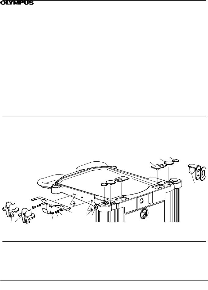
6.2Blanking caps & Cable tidy replacement
(1)Refer to Figure 6-1. Blanking caps: Cable port (item 17), Monitor (item 18) and Scope pole (item 19) are a push fit and so require to be carefully prised out of position.
(2)Unscrew Handknob (item 31) to release Cable tidy (item 29).
FIGURE 6-1 |
182 |
192 |
|
BLANKING CAPS & CABLE TIDY |
|||
172 |
|
29
21 |
372 502 472 |
20 |
672 |
31 |
|
|
|
|
6.3Bracket twin LG holder replacement
(1)Refer to Figure 6-1 . and using 4mm hex drive tool bit remove Bracket twin LG holder (item 20) release two screws (item 37) and washer crinkle (item 50) with washer (item 47) from jetnut (item 67).
(2)Replace/refit in reverse order. Using 4mm hex drive tool bit in torque driver ensure that screw (item 37) is tightened to a torque of 6Nm.
|
Page 17 of 76 |
WM--P1 SERIES WORKSTATIONS |
Issue 20 : July 2012 |

6.4 Rear panel replacement
Each Rear panel is available as a kit which inclues two feet and a finger latch pack. Fit the finger latch as shown in Figure 6-2 and discard the keeper plate, if supplied.
WM--NP1 Rear panel -- part no K10005044. WM--WP1 Rear panel -- part no K10005045
(1)Refer to Figure 6-2, pull the finger latch to release the top of the rear panel.
(2)Lift the rear panel from the two studs on the base of the workstation.
(3)Refit /replace the rear panel.
FIGURE 6-2
REAR PANEL REPLACEMENT
Discard


 keeper plate
Finger latch
Contents of
Finger latch pack
|
|
|
|
WM--NP1 |
|
WM--WP1 |
|||||
Rear panel |
|||||
Rear panel |
|||||
|
|||||
6.5Shelf corner moulding replacement
(1)Refer to Figure 6-3 each corner buffer (item 23 & 24) may be levered off.
(2)Reassemble by pushing each buffer into place.
FIGURE 6-3
SHELF CORNER MOULDINGS
24 


 23
23 


|
Page 18 of 76 |
WM--P1 SERIES WORKSTATIONS |
Issue 20 : July 2012 |

6.6 Castor replacement
Each workstation has two lockable castors (item 4) and two free castors (item 3). |
|
||
Maintenance/Repair kits available:-- |
|
|
|
Free castor kit |
K10004627 |
Braked castor kit |
K10004626 |
Castor free kit WM--P1 series A/S K10005041 |
Castor braked kit WM--P1 series A/S |
K10005040 |
|
Special tool : |
|
|
|
Castor spanner WM--P1 series |
K10005023 |
|
|
(1)Disconnect all power to the workstation.
(2)Remove rear panel and all equipment.
(3)Where fitted remove the scope pole or IV pole.
(4)Where fitted stow Keyboard Tray or Keyboard Arm -- Side Mounted.
(5)Remove the cable winder (item 19)
(6)Place the workstation carefully on to it’s back. The WM--DP1 exceeds 30Kg and must be handled by two people.
(7)Refer to Figure 6-4. For ease of access to the lower castors elevate and securely support the base end of the workstation.
(8)Using Castor spanner tool K10005023 fitted to a 1/2” drive wrench release the castor (item 3 or 4) and washer (item 5).
(9)Ensure that lockable castors(item 4) are refitted in the original location, refer to Figure 6-4 Run a M12 tap through the castor fixing hole to clear any residual Loctite adhesive.
When attaching a castor ensure that the thread of the bolt is smeared with loctite 243 ( item 60 ), use Castor spanner tool K10005023 fitted to a torque driver to tighten to a torque of 30Nm.
NOTE If Castor spanner tool K10005023 is not used, then the torque value on the driver should be set to 38Nm. Stand the workstation on it’s castors, re--install the equipment.
To allow the loctite to cure, the workstation should be kept in a location for 24 hours where the temperature is not below 22 C and manouvering on bumpy surfaces is avoided.
|
|
|
5 |
FIGURE 6-4 |
|
5 |
4LOCKABLE |
CASTOR REPLACEMENT |
|
3 |
|
|
|
|
|
|
|
|
5
4LOCKABLE
Support
5
3
CASTOR SPANNER WM--P1 SERIES -- K10005023
|
Page 19 of 76 |
WM--P1 SERIES WORKSTATIONS |
Issue 20 : July 2012 |

6.7Remote switch replacement
(1)Unplug the Remote switch plug from the separation transformer.
(2)Refer to Figure 6-5 for WM--NP1, Figure 6-6 for WM--WP1 and Figure 6-7 for WM--DP1, use a No 2 Pozi drive tool to release four screws (item 77) securing four p clips (item 78).
(3)Release the remote switch cable from releasable cable tie (item 34).
(4)Free the cable from the column side cable retainer.
(5)Using 4mm hex drive tool release two screws (item 40) with washer (item 50) to release remote switch (item 2).
(6)Reassemble in reverse order, use 4mm hex drive tool in torque wrench to tighten remote switch fixings to 2Nm.
(7)Fit four p clips to remote switch cable. Use a No 2 pozi driver in a torque wrench to fasten four screws (item 77) securing four p clips (item 78) tighten to torque of 2.2Nm.
(8)Route the remote switch cable to releasable cable tie (item 34). Take up any slack in the cable toward the switch and tighten the cable tie.
(9)Plug the Remote switch cable into the separation transformer.
(10)Route remaining cable into column side cable retainer.
|
Page 20 of 76 |
WM--P1 SERIES WORKSTATIONS |
Issue 20 : July 2012 |
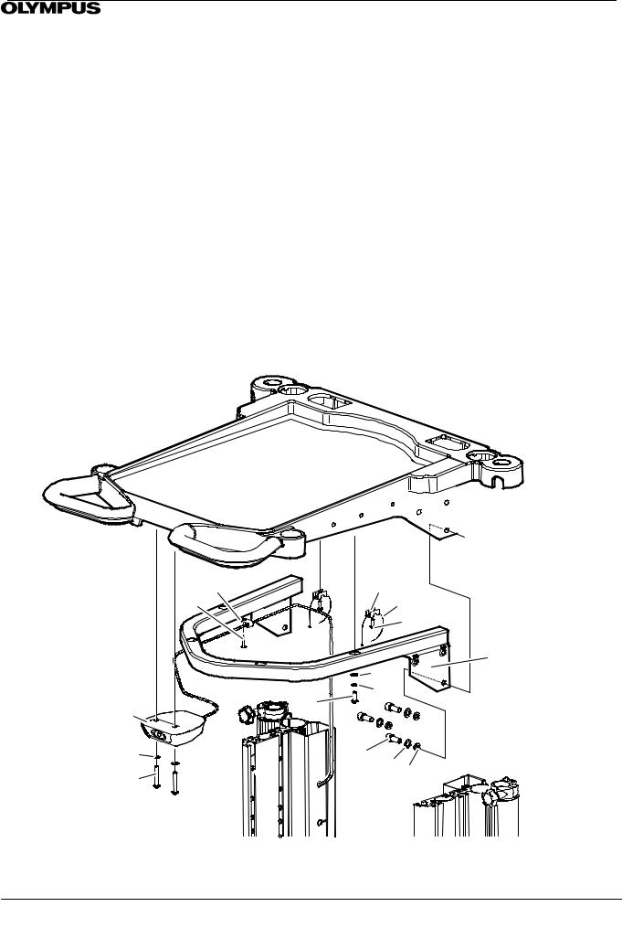
6.8Top Tray replacement WMNP1
(1)Remove all equipment from the top tray (item 14)
(2)Refer to Section 6.7 and remove the Remote switch assembly and cable (item 2) from the top tray.
(3)Refer to Figure 6-5 to release Support plates WM--DP1 (item 10) and Top tray (item 14). Using a 6mm allen key unscrew six screws (item 75) with washer crinkle (item 49) and washer (item 45).
(4) Reassemble in reverse order. Place top tray assembly into place between the side columns. Position each Support plate WM--DP1 (item 10) insert but do not fully tighten, three screws (item 75) with washer crinkle (item 49) and
washer (item 45) using 6mm hex drive tool. Using 6mm hex drive tool in torque wrench fully tighten to 20Nm.
(5)Refer to section 6.7 to refit remote switch.
784
774 2.2Nm


10
2


 502
502 


402 2Nm
FIGURE 6-5
WM--NP1 REMOTE SWITCH &
TOP TRAY REPLACEMENT
 14
14
322 


 342
342

 422 2Nm
10 
756 20Nm496 456
|
Page 21 of 76 |
WM--P1 SERIES WORKSTATIONS |
Issue 20 : July 2012 |
6.9Top Tray replacement WMWP1
(1)Remove all equipment from the top tray (item 14)
(2)Refer to Section 6.7 and remove the Remote switch assembly and cable (item 2) from the top tray.
(3)Refer to Figure 6-6. Using a 6mm allen key unscrew six screws (item 75) with washer crinkle (item 49) and washer (item 45).
(4)Remove and invert the top tray. Using a 6mm allen key relaese four screws (item28) with washer (item 50) and crinkle washer (item 45). Separate the Top tray (item 14) from Support top tray wide (item 15).
(5)Reassemble in reverse order. Secure top tray (item 14) to Top tray support wide (item 15) using a 6mm allen key to fasten four screws (item 28) with washer (item 50) and crinkle washer (item 47) Do not fully tighten.
(6)Place top tray assembly into place between the side columns. Using 6mm hex drive tool in torque wrench tighten six screws (item 75) with washer crinkle (item 49) and washer (item 45) to 20Nm.
(7)Fully tighten four screws (item 28) securing support toptray narrow to top tray using 6mm hex drive tool in torque wrench to 4Nm
(8)Refer to section 6.7 to refit remote switch.
FIGURE 6-6
WM--WP1 REMOTE SWITCH & TOP
TRAY REPLACEMENT
 14
14
774 2.2Nm784 |
322 |
342 |
422 2Nm
15
|
474 |
|
504 |
2 |
384 4Nm |
|
502 |
756 20Nm496 456 |
402 2Nm |
|
|
Page 22 of 76 |
WM--P1 SERIES WORKSTATIONS |
Issue 20 : July 2012 |
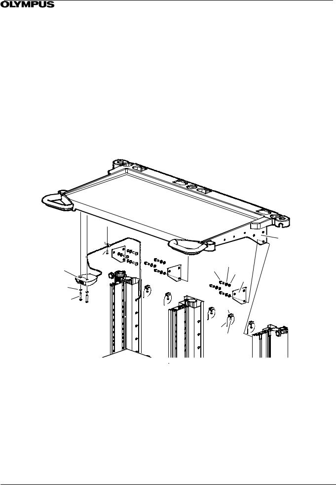
6.10Top Tray Replacement WMDP1
(1)Remove all equipment from the top tray (item 14)
(2)Refer to Section 6.7 and remove the Remote switch assembly and cable (item 2) from the top tray.
(3)Refer to Figure 6-7 to release Support plates WM--DP1 (item 10) and Top tray (item 14). Using a 6mm allen key unscrew nine screws (item 75) with washer crinkle (item 49) and washer (item 45).
(4)Reassemble in reverse order. Place top tray assembly into place between the side columns. Position each Support plate WM--DP1 (item 10) insert but do not fully tighten, three screws (item 75) with washer crinkle (item 49) and
washer (item 45) using 6mm hex drive tool. Using 6mm hex drive tool in torque wrench fully tighten to 20Nm.
(5)Refer to section 6.7 to refit remote switch.
FIGURE 6-7
WM--DP1 REMOTE SWITCH AND TOP
TRAY REPLACEMENT
784 |
|
|
|
|
14 |
774 2.2Nm |
75 |
49 |
9 |
|
|
2 |
9 2Nm |
45 |
9 |
||
502 |
|
|
|
10 |
|
|
|
|
|
|
|
402 2Nm |
|
325 |
|
|
|
|
|
|
|
|
|
|
345 425 |
|
|
||
|
Page 23 of 76 |
WM--P1 SERIES WORKSTATIONS |
Issue 20 : July 2012 |
 Loading...