


INSTRUCTIONS
DP73
MICROSCOPE DIGITAL CAMERA
This instruction manual is for the Olympus Microscope Digital Camera Model DP73. |
|
To ensure the safety, obtain optimum performance and familiarize yourself fully with |
|
the use of this camera, we recommend that you study this manual thoroughly before |
|
operating the camera. |
|
For image operations including recording, editing and saving, please refer to the |
|
online manual for the cellSens / OLYMPUS Stream Software. |
|
Retain this instruction manual in an easily accessible place near the work desk for |
|
future reference. |
AX8080 |

This device complies with the requirements of both directive 2004/108/EC concerning electromagnetic compatibility and directive 2006/95/EC concerning low voltage.
In accordance with European Directive 2002/96/EC on Waste Electrical and Electronic Equipment, this symbol indicates that the product must not be disposed of as unsorted municipal waste, but should be collected separately.
Refer to your local Olympus distributor in EU for return and/or collection systems available in your country.
NOTE: This equipment has been tested and found to comply with the limits for a Class A digital device, pursuant to Part 15 of the FCC Rules. These limits are designed to provide reasonable protection against harmful interference when the equipment is operated in a commercial environment. This equipment generates, uses, and can radiate radio frequency energy and, if not installed and used in accordance with the instruction manual, may cause harmful interference to radio communications. Operation of this equipment in a residential area is likely to cause harmful interference in which case the user will be required to correct the interference at his own expense.
FCC WARNING: Changes or modifications not expressly approved by the party responsible for compliance could void the user’s authority to operate the equipment.

DP73

CONTENTS
IMPORTANT — Be sure to read this chapter for safe use of the equipment. — |
1-11 |
|
||
1 |
Intended Use........................................................................................................................................................................................................................................................... |
5 |
|
|
2 |
Conformity of the System......................................................................................................................................................................................................................... |
5 |
|
|
3 |
Handling Precautions................................................................................................................................................................................................................................... |
13 |
|
|
4 |
Maintenance and Storage...................................................................................................................................................................................................................... |
14 |
|
|
|
|
|
|
|
|
1 SYSTEM CHART.................................................................................................................................................................................................... |
15 |
|
|
|
|
|
|
|
|
2 NOMENCLATURE............................................................................................................................................................................................... |
16 |
|
|
2-1 |
DP73/DP73 (For Desktop Computer)................................................................................................................................................................................................ |
16 |
|
|
2-2 |
[OPTIONAL] DP-PXU PCIe Extension Unit (For Laptop Computer)............................................................................................................ |
18 |
|
|
|
|
|
|
|
|
3 HARDWARE INSTALLATION.................................................................................................................................................................... |
19 |
|
|
1 |
Installing the Low-Profile Bracket.................................................................................................................................................................................................... |
19 |
|
|
2 |
Installing the PCIe Interface Board............................................................................................................................................................................................... |
19 |
|
|
3 |
Installing the Camera Head.................................................................................................................................................................................................................. |
23 |
|
|
4 |
Connecting the Cables.............................................................................................................................................................................................................................. |
25 |
|
|

DP73
4 |
SOFTWARE INSTALLATION...................................................................................................................................................................... |
29 |
5 |
IMAGE ACQUISITION PROCEDURE.......................................................................................................................................... |
31 |
6 |
EXTERNAL TRIGGERING.......................................................................................................................................................................... |
33 |
7 |
SPECIFICATIONS.................................................................................................................................................................................................. |
35 |
9 TROUBLESHOOTING GUIDE.............................................................................................................................................................. |
40 |
|

IMPORTANT
The DP73 microscope digital camera is designed to be connected to a camera adapter mounted on an Olympus UIS2/UIS series of optical microscope (not applicable to the LB series) for use in recording of microscopic magnified images at high speed and highest resolution while maintaining high picture quality and high color reproduction. The DP73 incorporates a variety of functions for supporting image recording under optimum conditions.
When the DP73 microscope digital camera is used with a camera adapter or a microscope from a manufacturer other than Olympus, the optical performance may not be manifested fully.
If the equipment is used in a manner not specified by this manual, the safety of the user may be endangered. In addition, the equipment may also be damaged. Always use the equipment as outlined in this instruction manual.
The following symbols are used to set off text in this instruction manual.
CAUTION : Indicates a potentially hazardous situation which, if not avoided, may result in minor or moderate injury or damage to the equipment or other property. It may also be used to alert against unsafe practices.
: Indicates commentary (for ease of operation and maintenance).
1

DP73
 SAFETY PRECAUTIONS
CAUTION Never connect or disconnect the interface cable while the standby switch  of the computer is set to ON. Otherwise, malfunction may result.
1.Before connecting or disconnecting the interface cable, make sure that the standby switch  of the computer is set to OFF.
When connecting the interface cable, push in the connector all the way and ensure that the connector will not slip out before setting the standby switch  to ON.
Do not move the computer or apply an impact to it while it is powered ON.
2.The cords and interface cables are vulnerable to bends or twists. Do not apply excessive force to them.
3.To prevent the microscope from toppling down, avoid using microscope attachments that may make the total height of the microscope above 1 meter when they are attached.
4.When installing the PCIe interface board, be sure to hold it by the edge. Never touch the board surface directly, as this will lead to malfunction.
2
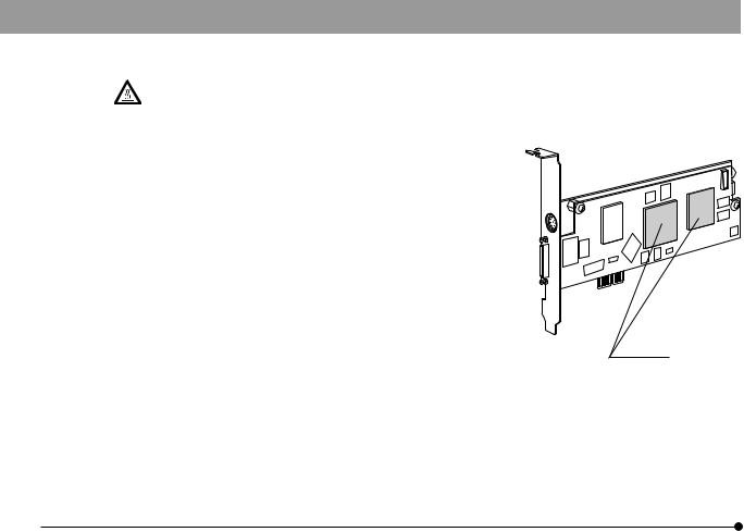
The area (IC) of the PCIe interface board becomes very hot during and immediately after use of the camera. Be careful never to touch them during and after use.
5. For handling of the computer, refer to the separately provided “Computer User’s Manual”. 6. Connect the power cord correctly and ensure that the grounding 
terminal of the power supply and wall outlet are properly connected. If the equipment is not grounded/earthed, Olympus can no longer warrant the electrical safety performance of the equipment. 7. Lay out the interface cable so that it does not contact the heat
generating section such as the lamp housing of the microscope. 8. After operation or in case of abnormality, be sure to disconnect the
power cord from the connector on the microscope or from the wall power outlet.
9. Never insert foreign objects into the air vents as this could result in fire and electrical shock.
3

DP73
 Computer and Software
The computer data may be destroyed by an unexpected event. Be sure to keep a backup of the data.
1.Olympus will not assume any liabilities for any damage incurred due to the use or non-usability of this system, including compensation for the lost data.
2.The computer used with this system should set up and run Microsoft Windows 7 Professional or Ultimate. For the OS in the computer, the user is requested to create a backup and retain it carefully. (Olympus does not support the matters related to the OS including its backup.)
For details on the computer and Microsoft Windows 7, refer to their respective manuals.
3.Olympus guarantees the quality of this product in the factory shipment condition.
Olympus will not assume any liabilities for the operation errors and functional faults incurred due to the alteration of the environmental setup (including BIOS change), installation of other software or addition of hardware to the computer by the user.
4.When the HDD free space reduces, the data processing speed may slow extremely or errors may occur frequently. To prevent this, delete unnecessary data files frequently. For how to delete data files, refer to the manuals for Microsoft Windows 7.
5.Never attempt to delete or rename the folders and files installed by the provided installer software. Otherwise, the software may get unable to be started up.
4

6.Do not open the housing of the computer and touch the power supply or the circuit board’s heat generating section right after use as it may burn your hand. Wait until the internal temperature drops sufficiently.
7.Sharp edges inside the computer may cut your fingers, so take extra care.
8.Use a computer that complies with the safety standards of your country.
1 Intended Use
This device is intended to be used for the capture of digital images for non-clinical diagnostic purposes.
2 Conformity of the System
Restrictions in Use
1.The applicable camera adapter is the U-TV0.5XC-3, U-TV0.63XC-1-2, MVX-TV0.63XC, U-TV1XC or the combination of U-TV1X-2 and U-CMAD3.
The U-TV0.5XC should not be used because it deteriorates the image flatness.
A camera adapter with a magnification below 0.5X cannot be used because part of image will be obscured.
2.When the DP73 is connected to the rear port of the U-DPT(double port tube) or U-MPH(multi port head), the peripheral part of the recorded image may be deteriorated due to the optical performance of the U-DPT or U-MPH.
5
DP73
3.When the U-TV0.5/C-2/U-TV0.5/C-3/U-TV0.63XC-1-2(C mount camera adapter) is used, using two or more intermediate attachments* may obscure the peripheral part of the field of view or may make flare noticeable.
*Example of two intermediate attachments with BX microscope :
Reflected light illuminator + intermediate attachment equivalent to the U-CA.
4.Under fluorescent ring illumination or other AC-driven illumination such as a phase control light intensity adjusting illumination system, the following phenomena may be observed by illumination light flickering because of high light intensity and shortened exposure time :
·· Flickering of the displayed image. ·· Instability in exposure.
·· Hatching patterns in pixel shift recording (4800 x 3600 or 2400 x 1800 pixels, 3CCD mode).
However, provided that the brightness can be adjusted using the light intensity control knob or ND filters, the above phenomena may be attenuated by adjusting the brightness so that the exposure time exceeds 1/50 sec.
For details on the microscope models using AC-driven illumination, contact Olympus.
5.Combinations of this product and non-Olympus microscopes have not been evaluated extensively. Non-Olympus microscopes and commercially available C-mount lenses can be used provided that they match a CCD with a size of no less than 1/1.8 inch and the lens projection length from the C-mount body attaching section is no more than 4.5 mm. However, problems due to optical adaptability, such as shading, may be observed.
6

6.When the specimen has a low contrast (near transparent) or high reflectance (mirror status) and the aperture iris diaphragm is stopped down near the smallest aperture, spot flare may be noticeable.
7.When the edge of a non-transmitting object is observed under the STM6 (small measuring microscope) transmitted illumination, flare may be noticeable due to the difference in brightness between the transmitted sections (over-exposure) and non-transmitting sections (under-exposure). To reduce the flare, set a lower exposure using the exposure correction function or setting the exposure manually.
8.When a low-power objective (below 4X) is used, the peripheral part of the field of view may be obscured. In this case, use an ultralow-magnification condenser (U-ULC-2).
9.When the U-CFU (real time confocal unit) is used, it is required to set the exposure to a longer period than 1/30 sec. using the manual exposure mode and control the brightness by engaging or disengaging ND filters.
10.When the specimen has large difference in brightness, particularly when the bright part of the specimen comes on the upper part of the image, red and horizontal flare may be observed. It is noticeable when the AS is being closed. The flare will get unnoticeable when the AS is being opened, though the flare may not be completely removed.
11.When a specimen with high reflectivity is observed with reflected light brightfield observation through the beam splitter of the eyepiece/camera light path of a trinocular tube in combination with the U-TV0.5XC camera adapter, the image in the area outside the CCD’s effective image pickup area may be observed as vague ghosts in the peripheral area of the visual field of eyepiece.
7

DP73
12.Flare may be produced during reflected light darkfield observation under overexposure To reduce the flare, use the exposure correction function or reduce the exposure with manual exposure control.
13.During image acquisition with pixel shifting (4800 x 3600 or 2400 x 1800 pixels, 3CCD mode), the image may be disturbed if the specimen is moved.
14.If the camera or microscope is vibrated during image acquisition with pixel shifting (44800 x 3600 or 2400 x 1800 pixels, 3CCD mode), the image will be disturbed. There are several causes for the vibration which are for example the operation of keyboard/mouse on the same table where the microscope equipped with the camera is placed, or vibration from the instrument erquipped with an air cooling fan, etc.
Operating Environment
Temperature: 10 to 35°C.
Humidity: 20% to 85% (without condensation).
See page 39 for details.
Recommended Monitor Specifications
·· A monitor with the 1280 x 1024 or larger full-color display capability.
·· An Adobe RGB compatible monitor, provided that the camera head is used in the Adobe RGB mode.
8

Recommended Computer Specifications – Desktop Computer –
1. Computer requirements
|
PC/AT compatible |
CPU |
Intel Core series 1.8 GHz or greater [Core2 Duo E6400, 2.13 GHz or greater recommended] |
RAM |
4 GB or more |
HDD |
Free space 1 GB or more |
Graphic |
PCI Express X16 VGA card with 1280 x 1024 or more and 32-bit color capability. |
|
On-board graphic also acceptable. |
Extension slot |
PCI Express Rev. 1.0a or later. |
|
Half-size or low-profile PCIe board compatible (106.7 mm x 174.6 mm) |
OS |
Windows 7 Professional/Ultimate (64 bit) |
|
Language: English or Japanese |
Power |
250 W or more. (With CE marking) |
|
* There needs to be the FDD power cable, HDD(4-pin) power cable or SATA power cable |
|
which is not occupied. |
2.CPU
We do not guarantee performance if the computer uses a CPU other than or incompatible with Core series or uses a non-Intel chipset.
9

DP73
3.HDD free space
The HDD free space (the value 1GB or more in Page 9) is the space that does not cause a special problem when the system is installed or run. The space required for saving an image file in the HDD is slightly more than 5.6 MB with a 1600 x 1200-pixel (24-bit) non-compressed image and slightly more than 50 MB with a 4800 x 3600-pixel (24-bit) non-compressed image. In consequence, the HDD should also provide a considerably large space for saving these image files.
When saving movies in the HDD stack, the space required for saving a movie is about 80 MB (max.) per second. The movie recording time is limited according to the HDD free space.
4.RAM
If a RAM other than a PC2700 or greater, dual-channel RAM is used, the full-size live frame rate may drop.
5.Monitor
Us an Adobe RGB compatible monitor when using the camera head in the Adobe RGB mode.
Optimum color reproduction is not available if the sRGB/Adobe RGB setting of the camera head does not match the setting of the monitor.
6.Sequential connection of PCIe units
Up to two PCIe units including the DP73 and a PCI interface board of the DP72/DP71/DP70/DP30BW or FV1000 (FV10-ASW-V1.5 or later) can be connected in series. Series connection of the FV300/FV500 is not possible.
However, their simultaneous operation is not available so it is required to select either PCI interface operation.
10

7. Power supply
The PCIe interface board should be powered by connecting the FDD power supply connector from the ATX power supply in the computer.
If your computer does not have an available FDD power cable or the FDD power cable is too short, use the provided HDD(4-pin) to FDD power conversion cable for the power supply.
And if your computer does not have an available HDD power cable (4-pin), use the provided SATA-to-HDD(4- pin) power conversion adapter and HDD(4-pin)-to-FDD power conversion cable for the power supply.
Recommended Computer Specifications – Laptop Computer –
1. Computer requirements
|
PC/AT compatible |
CPU |
Intel Core series 1.8 GHz or greater [Core2 Duo T7300, 2.0 GHz or greater recommended] |
RAM |
4 GB or more |
HDD |
Free space 1GB or more |
Graphic |
On-board graphic with 1280 x 1024 or more and 32-bit color capability. |
Card slot |
ExpressCard/34 or ExpressCard/54 |
OS |
Windows 7 Professional/Ultimate (64 bit) |
|
Language: English or Japanese |
11

DP73
2.CPU
We do not guarantee performance if the computer uses a CPU other than or incompatible with Core series or uses a non-Intel chipset.
3.HDD free space
The HDD free space (the value 1GB or more in Page 9) is the space that does not cause a special problem when the system is installed or run. The space required for saving an image file in the HDD is slightly more than 5.6 MB with a 1600 x 1200-pixel (24-bit) non-compressed image and slightly more than 50 MB with a 4800 x 3600-pixel (24-bit) non-compressed image. In consequence, the HDD should also provide a considerably large space for saving these image files.
When saving movies in the HDD stack, the space required for saving a movie is about 80 MB (max.) per second. The movie recording time is limited according to the HDD free space.
4.RAM
If a RAM other than a PC2700 or greater, dual-channel RAM is used, the full-size live frame rate may drop.
5.Monitor
Us an Adobe RGB compatible monitor when using the camera head in the Adobe RGB mode.
Optimum color reproduction is not available if the sRGB/Adobe RGB setting of the camera head does not match the setting of the monitor.
6.ExpressCard
The ExpressCard tends to slip out easily from the computer. Be sure not to disconnect the ExpressCard during operation. For protection from possible damage, do not apply exessive force to the ExpressCard. Insert or remove the ExpressCard after the PC is shut down.
12

3Handling Precautions
1.This camera head is a precision instrument. Handle it with care and avoid subjecting it to a sudden or severe impact.
2.The image displayed on the monitor may be affected when it is used at a place close to equipment generating strong electromagnetic waves. This is not a malfunction and will not affect the actual image being recorded. To avoid interference during operation, keep the system far from any source of electromagnetic waves.
3.As the camera head is heavy, hold it carefully not to drop when mounting or storing.
4.Do not use the camera in areas where it may be subjected to direct sunlight, high temperature, humidity, dust, or vibrations. (For the operating environment conditions, see chapter 8, “SPECIFICATIONS“ on page 35.)
5.Be sure to install the PCIe Extension Unit without blocking the opening for ventilation provided on it.
6.The camera head needs to be calibrated periodically (approx. every 3 months) for the level variations caused by the influence of cosmic rays. For the calibration method, refer to the CCD Calibration in the online manual for the cellSens or OLYMPUS Stream software.
7.As a countermeasure against computer virus infection, it is recommended to install an anti-virus software on the PC. Operation speeds of the cellSens/OLYMPUS Stream may slow down depending on the anti-virus software.
13
 Loading...