


Macro Flash System / Makro-Blitz-System
System de flash gros plan / Sistema de flash macro
Macro Flash Controller FC-1
Ring Flash RF-11 / Twin Flash TF-22
Makro-Blitz-Steuerung FC-1
Ringblitz RF-11 / Zweifachblitz TF-22
Controleur de flash en gros plan FC-1
Flash annulaire RF-11 / Flashes jumeaux TF-22
Controlador de flash para macro FC-1
Flash de anillo RF-11 / Flash doble TF-22
Instructions |
2 |
Bedienungsanleitung |
53 |
Mode d’emploi |
107 |
Instrucciones |
161 |

Thank you for purchasing the OLYMPUS Macro Flash System. Before use, please read this instruction manual to ensure your safety, and keep it handy for future reference.
SAFETY PRECAUTIONS (Be sure to read and observe the following.)
This instruction manual uses a variety of common symbols and icons to assist you in proper handling and usage of this product, and to warn you of potential hazards to yourself and others as well as to property. These symbols and their significance are described below.
 DANGER
Failure to observe the precautions indicated by this symbol may result in serious injury or death.
 WARNING
Failure to observe the precautions indicated by this symbol may result in injury or death.
 CAUTION
Failure to observe the precautions indicated by this symbol may result in injury or property damage.
Symbols for prohibiting action |
Symbol instructing action |
||
Prohibited |
Disassembly |
Mandatory |
|
prohibited |
|||
|
|
||
For customers in Europe
The “CE” mark indicates that this product complies with the European requirements for safety, health, environment and customer protection. CE-mark products are for sale in Europe.
For customers in USA FCC Notice
This device complies with part 15 of the FCC rules. Operation is subject to the following two conditions:(1) This device may not cause harmful interference, and (2) this device must accept any interference received, including interference that may cause undesired operation.
Any unauthorized changes or modifications to this equipment would void the user’s authority to operate.
For customers in CANADA
This Class B digital apparatus complies with Canadian ICES-003.
This Macro Flash System has been designed exclusively for use with Olympus digital cameras. Do not connect the Macro Flash System to a camera not manufactured by Olympus, as this may result in a malfunction or damage to the camera and/or Macro Flash System.
 DANGER
The Macro Flash System incorporates high-voltage circuitry. Never attempt to disassemble or modify it, as this may result in electric shock and/or injury.
Do not touch the ring flash connector or twin flash connector terminals on the FC-1 Macro Flash Controller.
Do not use the Macro Flash System where it may be exposed to flammable or explosive gas. Otherwise, fire ignition or explosion may result.
To prevent a traffic accident, do not direct the flash towards the driver of a car.
2

 WARNING
Do not fire the flash or AF illuminator light immediately in front of a person’s eyes (particularly an infant). Exposure to the light from the flash at a very short range may cause irreparable injury to the eyes. Be especially careful to avoid using the Macro Flash System at a distance of less than 1 meter from an infant.
Do not leave the Macro Flash System and batteries within reach of children.
•If a child swallows a battery or small accessory, see a doctor immediately.
•If the flash is emitted near a child, their eyes may be injured irreparably.
•Moving parts of the Macro Flash System could injure a child.
Avoid the following actions to prevent fire or injury due to battery fluid leak, overheating, fire ignition or bursting.
•Do not use batteries that are not specified for use with this Macro Flash System.
•Do not throw the battery in a fire, expose it to heat, short-circuit it, or disassemble it.
•Do not mix old and new batteries, or batteries of different types or brands.
•Do not attempt to recharge non-rechargeable batteries such as alkaline batteries.
•Do not load batteries with the +/– polarity reversed.
Do not store the Macro Flash System in a place exposed to excessive dust or moisture. Otherwise, fire or electric shock may result.
Do not use the flash when it is covered by a flammable object such as a handkerchief. Do not touch the light-emitting area after use. It will be very hot and could burn you.
If the Macro Flash System is dropped in water or any fluid gets inside, immediately remove the batteries and contact your dealer or Olympus. Continued use could result in fire or electric shock.
 CAUTION
If you notice any abnormalities such as leakage, discoloration, deformation, overheating, or odor, stop using this device. Continued use could result in fire, overheating or explosion. Remove the batteries carefully to avoid burning yourself and to prevent exposure to gas or dangerous fluids that may be released. For repair, contact Olympus.
Always remove the batteries when you don’t expect to use the Macro Flash System for a long period. Other-
wise, heat generation or fluid leak from the batteries may result in fire, injury and/or contamination of the surroundings.
Do not use a leaking battery. Doing so could result in fire or electric shock. Please contact your dealer or Olympus.
Do not handle the Macro Flash System with wet hands. Doing so could result in electric shock.
Do not leave the Macro Flash System in a place where it may be exposed to high temperatures. Otherwise, deterioration of parts or fire may result.
Do not take out the batteries immediately after using the Macro Flash System continuously for a long period. Otherwise, the hot batteries may cause burns.
Do not deform the battery compartment or allow any foreign objects to get inside.
3

HANDLING PRECAUTIONS
The Macro Flash System is composed of precision electronic parts. Absolutely avoid using or storing the Macro Flash System in the following places, as this may result in malfunction or failure.
•Under direct sunlight, on a beach, etc.
•Anywhere exposed to high temperature and humidity or rapid fluctuations in temperature and humidity.
•Any place exposed to excessive sand, dust or dirt.
•Near a fire.
•Near an air conditioner or air humidifier.
•Any place exposed to water or moisture.
•Any place subject to vibrations.
•Inside an automobile.
Do not apply a strong vibration or shock to the Macro Flash System by dropping it or hitting it against something.
When the Macro Flash System has not been used for a long period, mold or moss may form. This can cause a malfunction. To prevent this, it is recommended to check the operations before using the Macro Flash System after a long period of storage.
Do not touch the electric contacts of the Macro Flash System to prevent malfunction.
To prevent overheating and deterioration of the light-emitting section, do not continue full activation more than 40 times in a row. After firing the flash 40 times successively, do not use the flash for at least 10 minutes to allow the light-emitting section to cool down.
BATTERY PRECAUTIONS
Use only the specified batteries. |
|
|
• AA (R6) alkaline dry cell batteries (LR6 type) ..................... |
x 4 |
|
• AA (R6) |
Ni-Cd batteries ...................................................... |
x 4 |
• AA (R6) |
Ni-Mh batteries ..................................................... |
x 4 |
• AA (R6) Ni-Mn batteries (ZR6 type) ................................... |
x 4 |
|
• AA (R6) lithium batteries (FR6 type) ................................... |
x 4 |
|
• Lithium battery packs (CR-V3 type) (Olympus LB-01) ....... |
x 2 |
|
*AA (R6) manganese batteries cannot be used.
Be sure to observe the following points. Otherwise, battery fluid leak, overheating, fire ignition and/or bursting may result.
•Do not mix old and new batteries, recharged and discharged batteries, batteries of different capacities, or batteries of different types or brands.
•Do not attempt to recharge non-rechargeable batteries such as alkaline batteries.
•Do not load or use the batteries with the +/– polarity reversed. If the batteries do not fit smoothly in the battery compartment, do not force them.
•Never use a battery if its outer coating (insulation) has been partially or entirely peeled off. Otherwise, leakage, overheating or explosion may result.
•Some brand-new batteries may also have their outer coating (insulation) peeled off completely or partially. Never use these batteries.
Do not use the following kinds of batteries.
Outer coating (insulation) is peeling or
has peeled off.
The negative end is slightly swollen and is not covered by the coating (insulation).
The negative end is flat (whether or not a part of the negative pole is covered by the coating).
4

All rechargeable batteries must be recharged using the specified battery charger, simultaneously and completely. Be sure to read the battery and battery charger instruction manual.
Improper use of batteries may result in fluid leak, heat generation and/or damage. Sweat and oil smudges
may cause battery contact failure. To prevent this, remove any stain completely with a dry cloth and insert the batteries by observing the +/– polarity.
In general, battery performance will be temporarily reduced as the ambient temperature drops. When using batteries in a cold place, keep them warm by keeping the Macro Flash System in cold protection gear or clothing.
If battery fluid gets on your skin or clothes, it may irritate your skin. Immediately rinse your skin or clothes with clean water.
If battery fluid comes in contact with your eyes, blindness may result. Rinse your eyes with clean water without rubbing them and see a doctor immediately.
Do not apply a strong shock to a battery or throw it.
When traveling, it is a good idea to carry spare batteries with you. In some countries, it may be difficult to obtain certain batteries.
Do not immerse batteries in water or moisten the terminals at its both ends.
If the +/– terminals of a battery are stained with sweat or oil smudges, contact failure may result. Clean the terminals well with a dry cloth before using the batteries.
Do not throw a battery in fire or heat it.
When disposing of batteries, be sure to follow local regulations.
When disposing of a rechargeable battery, insulate the +/– terminals with pieces of tape and take them to your nearest rechargeable battery recycling center.
Note on the cameras used with the Macro Flash System
●The functions available from the Macro Flash System are limited with certain digital cameras. For details, please check the Olympus website (http://www.olympusamerica.com/E1).
Before reading this manual
○The information in this manual may be subject to change without notice.
○This manual has been compiled as carefully as possible. However, if you have any questions or wish to report an error or omission, please contact Olympus.
○Duplication of this manual in part or in whole without permission of Olympus is prohibited except for personal use. Reproduction of the contents of this manual without permission of Olympus is strictly prohibited.
○Olympus will not assume any liability for damages, loss of profit or claims from any third party incurred due to improper use of this product.
○Olympus will not assume any liability for damages and loss of profit related to the loss of image data due to a failure of this product, servicing by a third party not designated by Olympus, or any other reason.
○Note that the quality of pictures shot with this product differs from the quality of pictures taken with ordinary film-based cameras.
Trademark information
All brand names and product names mentioned in this manual are the trademarks or registered trademarks of their respective owners.
5

CONTENTS |
|
• Macro Flash System ...................................................................................................................... |
7 |
• Checking the Package Contents ................................................................................................... |
8 |
• Applicable Cameras and Lenses ................................................................................................... |
9 |
• Nomenclature .............................................................................................................................. |
10 |
• Case for Macro Flash System ..................................................................................................... |
12 |
• Macro Flash Controller FC-1 ....................................................................................................... |
13 |
Loading batteries ................................................................................................................. |
13 |
Attaching to the camera/Removing from the camera .......................................................... |
14 |
• Ring Flash RF-11 ......................................................................................................................... |
15 |
Attaching to the camera ...................................................................................................... |
15 |
Checking the battery power ................................................................................................ |
16 |
Selecting the control mode .................................................................................................. |
18 |
Using the illuminators .......................................................................................................... |
19 |
TTL AUTO ........................................................................................................................... |
20 |
MANUAL ............................................................................................................................. |
22 |
Light control range .............................................................................................................. |
24 |
• Twin Flash TF-22 ......................................................................................................................... |
27 |
Attaching to the camera ...................................................................................................... |
27 |
Checking the battery power ................................................................................................ |
29 |
Selecting the control mode .................................................................................................. |
31 |
Adjusting the firing angle ..................................................................................................... |
32 |
Using the illuminators .......................................................................................................... |
33 |
TTL AUTO ........................................................................................................................... |
34 |
MANUAL ............................................................................................................................. |
37 |
Using the diffuser FDT-1 ..................................................................................................... |
41 |
Other operations ................................................................................................................. |
41 |
Light control range .............................................................................................................. |
42 |
• Custom Setup .............................................................................................................................. |
46 |
• All Reset ....................................................................................................................................... |
47 |
• Warning Display List .................................................................................................................... |
47 |
• Continuous Firing ......................................................................................................................... |
48 |
• Optional Accessories ................................................................................................................... |
49 |
• Q&A ............................................................................................................................................. |
50 |
• Main Specifications ...................................................................................................................... |
51 |
6

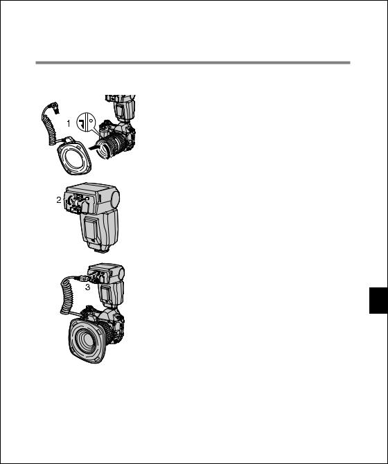
MACRO FLASH SYSTEM
=Ring Flash RF-11 |
(P.15) =Twin Flash TF-22 |
(P.27) |
This flash makes it possible to shoot a small subject without putting a shadow on it. It also makes possible various shooting techniques not available with ordinary flashes, such as close-up shooting in a hole.
This flash employs two flash lamps and allows more versatile flash activation for macro shooting. For example, you can enhance shading and depth by varying the firing angles, positions and
Twin Flash light ratio of the two flash lamps.You can also use just one of the two flash lamps.
The RF-11 Ring Flash and TF-22 must be connected to the FC-1 Macro Flash Controller for use.
When an Olympus Four Thirds System digital SLR camera is used, the TTL AUTO mode can be used to optimize exposure.
The RF-11 Ring Flash and TF-22 Twin Flash cannot be used simultaneously.
7

CHECKING THE PACKAGE CONTENTS 
Check that all of the parts and accessories shown in the following table are included in the package. If any item is missing or damaged, contact your dealer.
Products |
Products Available as Sets |
Products Available Individually |
||
|
Ring Flash Set |
Twin Flash Set |
Ring Flash |
Twin Flash |
Items |
SRF-11 |
STF-22 |
RF-11 |
TF-22 |
|
|
|
|
|
Macro Flash Controller FC-1 |
○ |
○ |
|
|
Ring Flash RF-11 |
○ |
|
○ |
|
Twin Flash TF-22 |
|
○ |
|
○ |
Shoe Ring SR-1 |
|
○ |
|
○ |
Diffuser FDT-1 |
|
○ |
|
○ |
Macro Flash Case |
○ |
○ |
|
|
Instructions (This manual) |
○ |
○ |
|
|
Items marked ○ are provided with each product.
This instruction manual applies to the SRF-11 and STF-22.
• Ring Flash RF-11 |
• Macro Flash Case |
|
•Macro Flash Controller FC-1
• Twin Flash TF-22 |
• Shoe Ring SR-1 |
• Diffuser FDT-1 |
8

APPLICABLE CAMERAS AND LENSES 
Olympus Four Thirds System Digital SLR Camera E-1
The Macro Flash System can be combined with this camera together with one of the Zuiko digital lenses marked with ○ in the following table.
|
|
|
○: Applicable. ×: Not applicable. |
Zuiko digital lens |
Ring Flash RF-11 |
Twin Flash TF-22 |
Remark |
|
|
|
|
ZUIKO DIGITAL ED50mm f2 Macro |
*○ |
*○ |
*: The optional FR-1 Flash Adapter Ring is required. |
|
|
|
|
ZUIKO DIGITAL 11-22mm f2.8-3.5 |
× |
○ |
|
|
|
|
|
ZUIKO DIGITAL 14-54mm f2.8-3.5 |
○ |
○ |
|
|
|
|
|
ZUIKO DIGITAL ED50-200mm f2.8-3.5 |
○ |
○ |
|
ZUIKO DIGITAL ED300mm f2.8 |
× |
× |
|
* How to use the FR-1 Flash Adapter Ring
For information on combining these flashes with upcoming Olympus digital cameras and lenses, check the Olympus website or contact Olympus Customer Support Center.
9

NOMENCLATURE 
Macro Flash Controller FC-1
Ring Flash connector (Page 15)
Twin Flash connector
(B) (Page 27)
Twin Flash release button (Page 28)
External power connector Connect the optional HV-1 Flash High-Voltage Pack.
Terminal cover
Control panel
Panel light button
Press to light up the control panel for about 15 seconds. The control panel lights up when controlled by a digital camera with communication capability.
Dial A
Ring Flash release button (Page 15)
Twin Flash connector
(A) (Page 27)
Lock ring
Lock pin (Page 14)
Electrical contact (Page 14)
Mode button (Pages 18 & 31)
Lamp button (Pages 19 & 33)
Auto Check lamp (Pages 20 & 34)
Battery compartment cover (Page 13)
Charge lamp/Test button (Pages 16 & 29)
Dial B |
Power button |
10
Control Panel Display
Twin Flash |
Control mode |
Ring Flash
Guide number (GN)
Setting display (GN, light intensity and light intensity adjustment)
Meter (Page 46) |
Feet (Page 46) |
* For simplicity, this figure shows the panel with all indicators lit.
Ring Flash RF-11
Twin Flash light ratio display (Pages 36& 40)
Light intensity adjustment (Pages 21, 23, 35 & 39)
Light emitting window
Connector terminal (Page 15)
Illuminator (Page 19)
11

Twin Flash TF-22
|
Connector terminal (Page 27) |
Mounting ring |
|
Light emitting |
Rotation ring |
|
|
|
Diffuser FDT-1 |
window |
|
(Page 41) |
Illuminator (Page 33) |
Rotation lock |
|
|
button |
Diffuser mounting |
|
|
|
|
groove |
|
|
Release button |
Shoe frame |
Tripod screw |
|
|
||
Shoe ring mount |
Tripod screw |
|
||
|
|
|||
(Page 41) |
|
|
(Shoe Ring SR-1) |
|
(TF-22 flash section) |
|
|
||
CASE FOR MACRO FLASH SYSTEM
The semi-hard case can accommodate all of the Macro Flash System components.
Ring Flash RF-11
Macro Flash Controller FC-1
Diffuser FDT-1
Flash Adapter Ring
FR-1 (optional)
Twin Flash TF-22
Shoe Ring SR-1
12

MACRO FLASH CONTROLLER FC-1
<Loading batteries>
Always use one of the following battery combinations |
|
|
• AA (R6) alkaline dry cell batteries (LR6 type) ...................... |
x 4 |
|
• AA (R6) |
Ni-Cd batteries ....................................................... |
x 4 |
• AA (R6) |
Ni-Mh batteries ....................................................... |
x 4 |
• AA (R6) Ni-Mn batteries (ZR6 type) ..................................... |
x 4 |
|
• AA (R6) lithium batteries (FR6 type) .................................... |
x 4 |
|
• Lithium battery packs (CR-V3 type) (Olympus LB-01) ......... |
x 2 |
|
* AA (R6) manganese batteries cannot be used.
How to load the batteries
1. Open the battery compartment cover.
2. Insert the batteries with correct +/– polarity.
3. Close the battery compartment cover.
AA (R6) type batteries |
CR-V3 |
The following product (optional) can also be used as an external power supply (page 49) :
• Flash High-Voltage Set SHV-1
Notes
•Do not mix old and new batteries or batteries of different types.
•Remove the batteries when the Macro Flash Controller is not going to be used for a long period.
•Carry spare batteries when traveling or when using the flash in cold areas.
•If the Power button of the FC-1 Macro Flash Controller is pressed when the RF-11 Ring Flash or TF-22 Twin Flash is not connected, the [RING] or [TWIN] indicator on the control panel blinks and the Macro Flash Controller turns off automatically (page 47).
13

14
RING FLASH RF-11
<Attaching to the camera>
•Attach the FC-1 Macro Flash Controller to the camera beforehand.
•To prevent the Ring Flash from falling off, attach it with the camera in a stable position.
1. While aligning the indices, attach the RF-11 Ring Flash to the lens.
2. Press the Ring Flash release button of the FC-1 Macro Flash Controller to remove the cap.
3. IInsert the RF-11 Ring Flash connector terminal into the
Ring Flash connector on the FC-1 Macro Flash Controller until it clicks.
• When unplugging the connector, be sure to press and hold the Ring Flash release button. Be sure to attach the cap after unplugging the connector.
• Do not pull the cord when plugging or unplugging the connector. Always grasp it by the connector plug. Pulling the cord could damage the connector wire.
Notes
•Confirm that both the Macro Flash Controller and Ring Flash are off before attaching or removing them. Otherwise, malfunction may result.
•Be sure to leave the Twin Flash connectors capped. Otherwise, the Macro Flash Controller cannot be turned on.
Memo
The Ring Flash and Twin Flash connector terminals are subject to high voltages. To ensure safety, the Macro Flash Controller is designed so that it cannot be turned on unless one of the flashes is connected to it and all of its unused connectors are capped.
15

<Checking the battery power>
CONTROLLER
MODE
LAMP
AUTO
CHECK
LIGHT |
TEST/ |
|
CHARGE |
RATIO GN/
POWER |
MACRO FLASH CONTROLLER
FC-1 |
MODE |
|
LAMP |
|
AUTO |
|
CHECK |
LIGHT |
CHARGE |
|
|
RATIO |
GN/ |
|
POWER |
MACRO FLASH CONTROLLER
FC-1 |
MODE |
|
|
LAMP |
|
|
AUTO |
|
|
CHECK |
|
LIGHT |
TEST/ |
|
CHARGE |
||
|
||
RATIO |
GN/ |
|
|
POWER |
1.Turn the camera on and then press the Power button to turn the Ring Flash on.
•The [RING] indicator appears on the control panel and battery charging starts.
Notes: • If the [RING] or [TWIN] indicator on the control panel blinks, wait until the blinking stops, then turn the camera off and re-connect the Ring Flash to the Ring Flash connector (page 47).
•Both Twin Flash connectors must be capped or the Ring Flash will not turn when the Power button is pressed.
2.Ensure that the Charge lamp lights up.
•Replace the batteries if the time taken for the Charge lamp to light up is longer than the values specified below.
Alkaline, Ni-Mn, lithium or
30 sec.
Ni-Cd batteries
Ni-Mh batteries |
10 sec. |
•If the Charge lamp and AUTO CHECK lamp blink alternately, it means that the battery capacity is running low. In this case, replace the batteries.
Memo: Test flash activation
To perform test flash activation, press the Test button.
MACRO FLASH CONTROLLER
FC-1 |
MODE |
|
LAMP |
|
AUTO |
|
CHECK |
LIGHT |
|
RATIO |
GN/ |
16
 Loading...