


INSTRUCTIONS
CKX41/CKX31
CULTURE MICROSCOPES
This instruction manual is for the Olympus Culture Microscopes Models CKX41 and CKX31. To ensure the safety, obtain optimum performance and to familiarize yourself fully with the use of this microscope, we recommend that you study this manual thoroughly before operating the microscope. Retain this instruction manual in an easily accessible place near the work desk for future reference.
A X 7 3 5 1

CKX41/CKX31
CONTENTS
IMPORTANT — Be sure to read this section for safe use of the equipment. — 1-3
1NOMENCLATURE
2CONTROLS
3 SUMMARY OF OBSERVATION PROCEDURE
4USING THE CONTROLS
4-5
6-7
8
9-15
|
4-1 |
Microscope Frame ............................................................................................................................................................................... |
|
|
9 |
|
|
|
1 |
Turning On the Light Source |
2 |
Adjusting the Brightness |
|
|
|
3 |
Adjusting the Tension of the Coarse Adjustment Knob |
|
||
|
4-2 |
Stage............................................................................................................................... |
|
...................................................................................... |
10 |
|
|
|
1 |
Placing the Specimen |
2 |
Moving the Specimen |
|
|
4-3 |
Observation Tube ....................................................................................................................................................................... |
|
|
11-14 |
|
|
|
1 |
Adjusting the Interpupillary Distance |
2 |
Adjusting the Diopter |
|
|
|
3 |
Using the Eye Shades |
4 |
Using Eyepiece Micrometer Disks |
|
|
|
5 |
Selecting the Light Path (U-TR30-2 Only) |
6 |
Adjusting the Tilt |
|
|
4-4 |
Illumination Column............................................................................................................................... |
|
......................................... |
15 |
|
|
|
1 |
Using the Filters |
2 |
Using the Aperture Iris Diaphragm |
|
|
|
3 |
Removing the Condenser Lens |
|
|
|
|
4-5 |
Objective Correction Collars ............................................................................................................................... |
|
.............. |
16 |
|
|
|
1 |
Correction Collar |
|
|
|
|
|
|
||||
5 |
PHASE CONTRAST OBSERVATION |
17-19 |
||||
|
|
|
||||
|
|
|
||||
6 |
PHOTOMICROGRAPHY & TV OBSERVATION |
20 |
||||
|
|
|
|
|
||
7 |
TROUBLESHOOTING GUIDE |
|
|
21-22 |
||
|
|
|
|
|
||
8 |
SPECIFICATIONS |
|
|
23-24 |
||
|
|
|
|
|
|
|
9ASSEMBLY — See this section for the replacement of the light bulb. — 25-29
|
........................................................PROPER SELECTION OF THE POWER SUPPLY CORD |
30-31 |
CKX41/CKX31
IMPORTANT
The difference between the CKX31 and CKX41 microscopes lie in the following basis systems.
|
CKX31 |
CKX41 |
|
|
|
|
|
|
Observation tube |
Binocular tube fixed |
Replaceable* |
|
|
|
Stage center plate |
– |
Replaceable** |
|
|
|
Reflected fluorescence system |
Not mountable |
Mountable |
|
|
|
*The U-CBI30-2/U-BI30-2/U-CTBI/CKX-TBI binocular tube or U-CTR30-2/U-TR30-2 trinocular tube can be mounted. But no intermediate attachment can be mounted.
**The standard stage center plate can be replaced with the CK40-CPG glass center plate, IX-CP50 center plate (50 mm), etc.
SAFETY PRECAUTIONS
³ ²
²
@
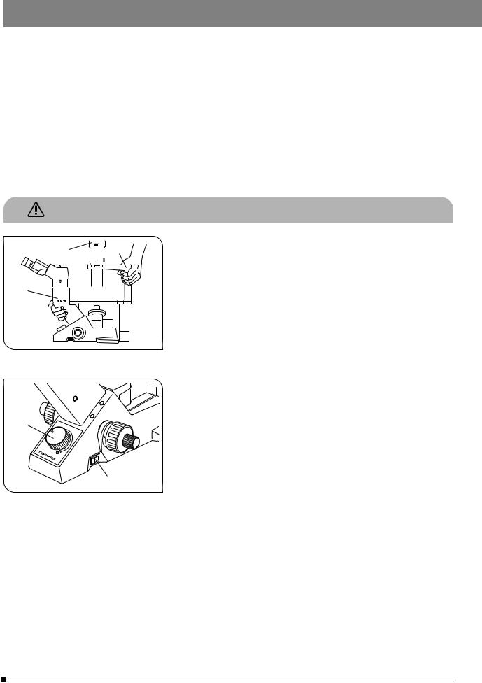
Fig. 1
5
4
Fig. 2
1.After the equipment has been used in an observation of a specimen that is accompanied with a potential of infection, clean the parts coming in contact with the specimen to prevent infection.
·Moving this product is accompanied with the risk of dropping the specimen. Be sure to remove the specimen before moving this product.
·In case the specimen is damaged by erroneous operation, promptly take the infection prevention measures.
2.Install the microscope on a sturdy, level table or bench (Weight: CKX31 about 8 kg, CKX41 about 8.8 kg).
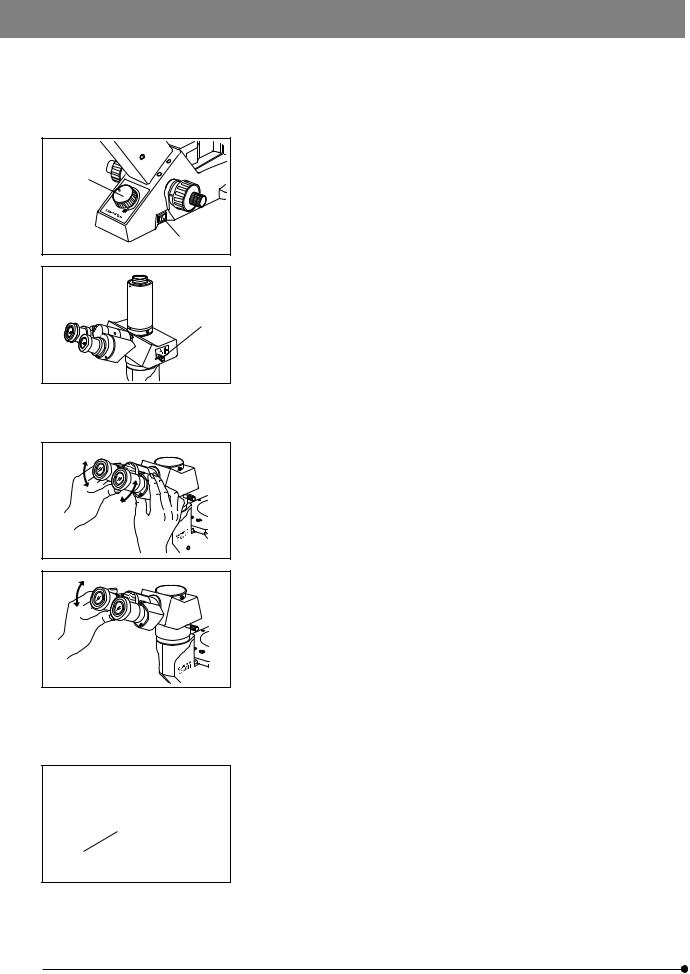
3.When transporting the microscope, be sure to keep it horizontal by holding it by the root of the observation tube relay tube 1 and the illumination column 2. (Fig. 1)
Be sure to remove the specimen since it may fall.
#Do not tilt it during carrying to prevent damaging the desktop or microscope.
4.Culture liquid or water spilt on the stage, objective or microscope frame may damage the equipment. Immediately disconnect the power cord from the wall outlet and wipe the liquid or water off if it is spilt on them.
5.The surfaces of the lamp socket 3 of the illumination column will become extremely hot during operation. When installing the microscope, make sure to allow ample free space around and in particular above the lamp socket. (Fig. 1)
When using the TV camera or photomicrographic system, install them so that the connection cable does not come in contact with the lamp socket.
6.To avoid potential shock hazards and burns when replacing the light
bulb, set the main switch 4 to “ ” (OFF) then disconnect the power cord from the wall outlet in advance. Whenever you replace the bulb during use or right after use, allow the lamp socket 3 and bulb to cool before touching. (Figs. 1 & 2)
Designated |
6V30WHAL high-intensity halogen bulb |
bulbs: |
(PHILIPS 5761) |
|
|
7.Always use the power cord provided by Olympus. If no power cord is provided, please select the proper power cord by referring to the section “PROPER SELECTION OF THE POWER SUPPLY CORD” at the end of this instruction manual. If the proper power cord is not used, product safety performance cannot be warranted.
8.Always ensure that the grounding terminal of the microscope and that of the wall outlet are properly connected. If the equipment is not grounded, Olympus can no longer warrant the electrical safety performance of the equipment.
1
9.The microscope system is unstable when the large camera back is attached. When pulling out the film, be sure to hold the microscope with one hand.
10.Always turn the light intensity control knob 5 gently. Do not attempt to turn it beyond the stop position. (Fig. 2)
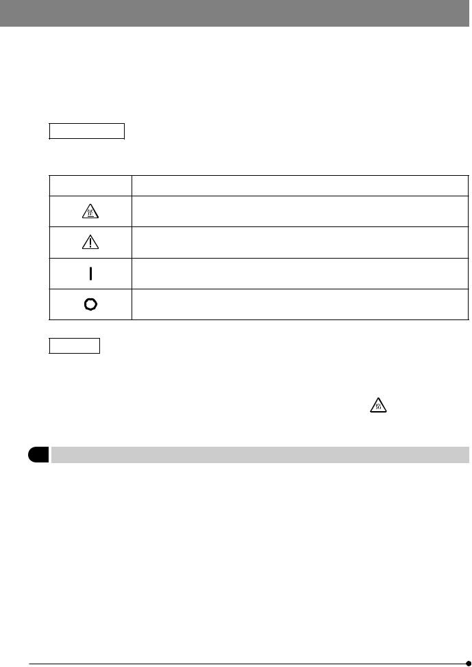
Safety Symbols
The following symbols are found on the microscope. Study the meaning of the symbols and always use the equipment in the safest possible manner.
Symbol |
Explanation |
|
|
Indicates that the surface becomes hot, and should not be touched with bare hands.
Before use, carefully read the instruction manual. Improper use could result in personal injury to the user and/or damage to the equipment.
Indicates that the main switch is ON.
Indicates that the main switch is OFF.
Warnings
Warning engraving is placed at parts where special precaution is required when handling and using the microscope. Always heed the warnings.
Warning engraving |
Lamp socket (U-LS30-3) |
||
position |
[Warning against high temperature] |
|
|
|
|||
|
|
|
|
1Getting Ready
1.A microscope is a precision instrument. Handle it with care and avoid subjecting it to sudden or severe impact.
2.Do not use the microscope where it is subjected to direct sunlight, high temperature and humidity, dust or vibrations. (For the operating conditions, see chapter 8, “SPECIFICATIONS”.)
3.Use the tension adjustment ring to adjust the rotation tension of the coarse adjustment knob.
4.For the applicable objectives, see chapter 8, “SPECIFICATIONS”. Olympus cannot guarantee the performance when other objective than specified is used.
2

CKX41/CKX31
2Maintenance and Storage
1.Clean all glass components by wiping gently with gauze. To remove fingerprints or oil smudges, wipe with gauze slightly moistened with a mixture of ether (70%) and alcohol (30%).
 Since solvents such as ether and alcohol are highly flammable, they must be handled carefully. Be sure to keep these chemicals away from open flames or potential sources of electrical sparks –– for example, electrical equipment that is being switched on or off. Also remember to always use these chemicals only in a well-ventilated room.
2.Do not attempt to use organic solvents to clean the microscope components other than the glass components. To clean them, use a lint-free, soft cloth slightly moistened with a diluted neutral detergent.
3.Be careful not to spill any liquid –– such as a culture solution –– on the unit. If you do spill anything, immediately set the main switch to “ ” (OFF) and unplug the power cord. Then wipe away any liquid on or under the objectives.
4.If no objectives are mounted, be sure to cover the objective mounting threaded positions on the revolving nosepiece to prevent and dust and spilled culture solution from getting on the lenses inside.
5.Do not disassemble any part of the microscope as this could result in malfunction or reduced performance.
6.When not using the microscope, keep it covered with a dust cover. Make sure the lamp socket is cool before covering the microscope.
7.Using a device that radiates ultraviolet light such as a germicidal lamp near the microscope may discolor (yellow) parts of the microscope surface. The amount of discoloration depends on the radiation intensity of the ultraviolet light and the distance between the microscope and radiation source. When not using the microscope, cover it with the dust cover. We recommend that you also cover the microscope with an impermeable sheet.
3Caution
If the microscope is used in a manner not specified by this manual, the safety of the user may be imperiled. In addition, the equipment may also be damaged. Always use the equipment as outlined in this instruction manual.
The following symbols are used to set off text in this instruction manual.
 : Indicates that failure to follow the instructions in the warning could result in bodily harm to the user and/or damage to equipment (including objects in the vicinity of the equipment).
# : Indicates that failure to follow the instructions could result in damage to equipment. } : Indicates commentary (for ease of operation and maintenance).
4Intended use
This instrument has been designed to be used to observe magnified images of specimens in routine and research applications.
Do not use this instrument for any purpose other than its intended use.
This device complies with the requirements of directive 98/79/EC concerning in vitro diagnostic medical devices. CE marking means the conformity to the directive.
NOTE: This equipment has been tested and found to comply with the limits for a Class A digital device,
pursuant to Part 15 of the FCC Rules. These limits are designed to provide reasonable protection
against harmful interference when the equipment is operated in a commercial environment. This
equipment generates, uses, and can radiate radio frequency energy and, if not installed and used in
accordance with the instruction manual, may cause harmful interference to radio communications.
Operation of this equipment in a residential area is likely to cause harmful interference in which case
the user will be required to correct the interference at his own expense.
FCC WARNING: Changes or modifications not expressly approved by the party responsible for compliance
could void the user’s authority to operate the equipment.
3
 NOMENCLATURE
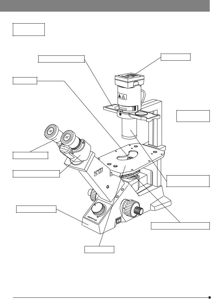
CKX31
Phase Contrast Slider
·Pre-centered Ph slider: IX2-SLP
·Ph centering slider: IX2-SL
Objectives
For brightfield observation: PlanCN 4X
PlanCN 10X
PlanCN 20X
PlanCN 40X
PlanCN 60X
PlanCN 100XO
#Dedicated objectives are required for phase contrast observations (see page 17).
Eyepieces (10X)
Binocular Tube (Fixed)
Microscope Frame
· CKX31SF
Stage (Fixed)
· Stage extension plate: CK2-SS · Mechanical stage: CK40-MVR
Lamp Socket
U-LS30-3
Illumination

 Column (Fixed)
Ultralong Working
Distance Condenser
Revolving Nosepiece (Fixed)
Quadruple revolving nosepiece
4

CKX41/CKX31
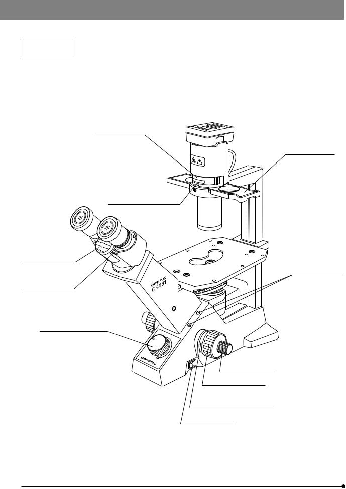
CKX41
Phase Contrast Slider
·Pre-centered Ph slider: IX2-SLP
·Ph centering slider: IX2-SL
Objectives
For brightfield observation: PlanCN 4X
PlanCN 10X
PlanCN 20X
PlanCN 40X
PlanCN 60X
PlanCN 100XO
#Dedicated objectives are required for phase contrast observations (see page 17).
Eyepieces
· WHB10X*
· WHN10X/WHN10X-H**
Observation Tube
· Binocular tube: U-CBI30-2*/U-BI30-2** · Trinocular tube: U-CTR30-2*/U-TR30-2**
· Tilting binocular tube: U-CTBI***/CKX-TBI* */** Only the eyepieces carrying the same marking “ * " or “ ** " as the observation tube marking can be attached.
*** Dedicated 10X eyepiece built in.
Microscope Frame
CKX41SF
Stage (Fixed)
Lamp Socket
U-LS30-3
Illumination Column (Fixed)
 Ultralong Working
Distance Condenser
Stage Center Plate
· Standard stage center plate
· Glass stage center plate: CK-40CPG
· Stage center plate (50 mm): IX-CP50
Revolving Nosepiece (Fixed)
Quadruple revolving nosepiece
·Stage extension plate: CK2-SS
·Mechanical stage: CK40-MVR
5
 CONTROLS
CKX31
}If you have not yet assembled the microscope, read chapter 9, “ASSEMBLY” (pages 25 to 29).
Filter holder (Page 29)
Phase contrast slider (Page 16)
Aperture iris diaphragm lever (Page 15)
Interpupillary distance scale (Page 11)
Slider centering knob
storage holes
Diopter adjustment ring (Page 12)
Light intensity control knob (Page 9)
Fine adjustment knob
Coarse adjustment knob
Coarse adjustment knob tension adjustment ring (Page 9)
Main switch (Page 9)
6
CKX41/CKX31
CKX41
}If you have not yet assembled the microscope, read chapter 9, “ASSEMBLY” (pages 25 to 29).
Filter holder (Page 29)
Interpupillary distance
scale (Page 11) Aperture iris diaphragm lever (Page 15)
Diopter adjustment ring (Page 12)
Light intensity control knob (Page 9)
Phase contrast slider (Page 16)
Standard stage center plate
Slider centering knob storage holes
Fine adjustment knob
Coarse adjustment knob
Coarse adjustment knob tension adjustment ring (Page 9)
Main switch (Page 9)
7
 SUMMARY OF OBSERVATION PROCEDURE
²
@
³
|
1.Set the main switch 1 to “ I ” (ON) and turn the light intensity control knob 2 to obtain appropriate brightness. (Page 9)
2.When using the U-TR30-2 trinocular tube, push in the light path selector knob 3 to set the light path at 100% for binocular observation. (Page 14)
3.Place a specimen on the stage. (Page 10)
4.Turn the revolving nosepiece to bring the 10X objective into the light path. Be sure to turn the revolving nosepiece until it clicks.
5.Adjust the interpupillary distance of the eyepieces. (Page 11)
6.Adjust the diopter of the eyepieces. (Page 12)
7.Bring the required objective into the light path and focus on the specimen.
8.When using the 40X objective provided with the correction collar, set the scale on the correction collar according to the thickness of the vessel bottom. (Page 16)
}When performing phase contrast observation, see pages 17 and after.
9.When observing an undyed specimen with brightfield, stop down the aperture iris diaphragm 4. In phase contrast observation, set the aperture wide open. (Page 15)
Bring the required filter into the light path. (Page 15)
10.In brightfield observation, use the LBD filter. In phase contrast observation,
use the IF550 green filter as required.
}In photomicrography, it is recommended to use the 45HA heat absorbing filter.
8
 Loading...