


MAINTENANCE MANUAL
CLV-180
ISSUE 1
FR-1700

CLV-180
INTRODUCTION
Introduction
This manual is intended for Olympus-certified technicians. Use of this manual by other individuals is prohibited.
Precautions
Before Repair
(1)Notify the site manager of the intent to repair the unit and obtain his/her approval before commencing.
(2)During repair, there is a risk of injury from the various tools and parts in the vicinity, as well as from fluid leakage on the floor. Inform the relevant people to restrict access to the repair area.
(3)To prevent potentially dangerous health risks, avoid working in a closed room, i.e., select a well-ventilated location when using organic solvents.
(4)In general, it is advisable to record the function and operation settings before repair, to enable restoration of the settings after service.
(5)If the original settings cannot be known due to mechanical problems present at the time the unit was accepted for repair, apply the factory-set values, or the safest settings (such as the lowest output levels). In such a case, inform the user that the settings have been changed.
(6)Guard against static electricity.
Use a conductive mat or wristband to discharge static electricity to prevent damaging the boards or other electrical components if it is necessary to touch them.
During Repair
(1)To prevent potentially dangerous health risks, thoroughly rinse any bodily areas that have come into contact with organic solvents as soon as possible.
(2)When using organic solvents, handle flames such as those in alcohol lamps with caution, because these solvents may ignite if exposed to flame.
In addition, always replace the lids back onto organic solvent containers before leaving the work-bench.
(3)Beware of electric shock.
Turn off the power and unplug the power cord before removing the cover of the unit.
(4)Beware of residual voltages.
The unit may contain residual charges in capacitor components. Take care to avoid electric shock when opening the top cover.
(5)To avoid personal injury and damage to the unit, heavy units should always be assembled or disassembled by at least two people.
(6)Repair with extreme caution to avoid injury.
Use extra caution around metal parts because the edges may be sharp.
(7)Reassemble parts according to their original configuration. This regards the following items especially:
a)Insulators, such as insulating tubes and mylar sheets.
b)Cable rerouting, clamps, and cores.
|
1 |
ISSUE1 |
INTRODUCTION |

CLV-180
c)Shield parts and cover screws with toothed washers.
Failure to attach parts in their original configurations, even if it does not impair product function, poses the risk of noise radiation and reduced electrical safety.
(8)Use specified parts.
The parts and components of this product are designed to operate under certain anticipated vibration, heat, chemical exposure, and voltage conditions. Always replace parts with those specified in the parts list.
(9)Always tighten nuts/screws to the specified torque and only use components of the specified dimensions.
(10)Do not reuse O-rings, E-rings, or packing. Always use new ones.
(11)When reusing components, remove sealing tape or sealing compound, and clean the components before use.
(12)Check that no screws or nuts are loose.
After Repair
(1)After repair, inform the site manager of the nature of the problems, the cause, the countermeasures taken, and the parts replaced.
(2)Always notify the site manager if, during repair, liquid disinfectants, cleaners, or alcohol were used. Inform the site manager that before using the unit, it is necessary to verify the concentration levels of disinfectants to ensure that they have not been diluted.
(3)Restore the original unit settings as they were recorded before repair. Request the presence of site manager to verify the settings with you.
Copyright
© 2005 Olympus Medical Systems Corp. All rights reserved. Unauthorized reproduction or distribution in part or in whole is prohibited.
Trademarks
OLYMPUS is a registered trademark of the Olympus Corporation.
The company names, product names, and proprietary technical terms in this document are the trade-marks or registered trademarks of their respective owners.
|
2 |
ISSUE1 |
INTRODUCTION |

Contents
Chapter 1: Product Specifications………………………………………...1-1
1Product Outline…………………………………..…………………………………………..1-2
2Features………………………….…………………..………………………………………..1-2
3Operational Conditions……………………………..……………………………………...1-3
4Specifications………….………………….…………..………………………………….…1-4
5Nomenclature and Functions…………………………………………..……………………..1-9 5-1 Front panel………………………………………………….…………………………….... 1-9 5-2 Control panel(buttons)……………………………………………………………………1-10 5-3 Control panel(indicators)………………………………………………………………...1-12 5-4 Rear and side panels……………………………………………………………………..1-14
Chapter 2: Troubleshooting………………………………………..…….2-1
1Contents……………………………………………………………………………………….2-2
2Troubleshooting…………………………...…………………………………………………….2-2 2-1 Power input failure…………………………………………………………..………….2-3 2-2 Lamp failure………………………………………………………………..………….2-4 2-3 Lamp malfunction…………….……………………………….…………..………….2-4 2-4 Scope connection failure………………………………………………………………….2-5 2-5 High-brightness malfunction……………………………………………………………..2-6 2-6 Cooling Fan malfunction………………………………………………………………….2-7 2-7 Shield malfunction at Scope removal…………………………………………………..2-7 2-8 Pump malfunction………………………………………………………………………….2-8 2-9 Filter Change Malfunction………………………………………………………………..2-9 2-10 Outgoing light failure……………………………………………………………………2-11 2-11 Manual Brightness failure……………………………………………………………...2-11 2-12 Automatic Brightness failure………………………………………………………….2-12 2-13 Panel Malfunction……………………………………………………………………….2-13 2-14 Emergency Lamp malfunction………………………………………………………..2-15 2-15 Back-up malfunction…………………………………………………………………..2-16 2-16 Lamp Life Meter Reset malfunction…………………………………………………2-16 2-17 Transillumination malfunction……………………………………………………….2-16
Chapter 3: Precaution on disassemble and reassembly……..…..….3-1
1Warn ing ……………………..……………………………………..……………………….3-2
2Cau t io n……………………………………………….…………………………………….3-2
Chapter 4: Assemble procedure…………………………..…..….4-1
1Jigs and Tools……………………………………………………………………………….4-2
2Areas……………………………………………………….…………………………………….4-2
3Disassembling and Reassembling procedure……………………………………………….4-3
Ch ap t er 5: Par t s L i s t ……....…………………………..…..….5-1
1Exploded Parts Diagram…………………………..…………………………………………….5-2
2Parts Li st …………………………………….…………………….….…..…………..………….5-10

Specification CLV-180
Chapter 1: Products Specifications
1-1
ISSUE1

Specification CLV-180
PRODUCT SPECIFICATIONS
1 Product Outline
Intended use:
When used in conjunction with an OLYMPUS endoscope, video system center, video monitor, accessories, and other related equipment, this product supports examination and endoscopic treatment by enabling observation through a fiberscope or through a video monitor.
Compatibility:
This product may be used in conjunction with EVIS 100/130/140 series videoscopes, EVIS EXERA 145/160 series videoscopes, EVIS EXERA II 165/180 series videoscopes, V series videoscopes, VISERA series videoscopes, rigid light guides, fiberscopes, as well as EVIS EXERA II CV-180/165, and endoscopic ultrasound systems.
Durability:
With adherance to the conditions listed below, this product has a usable life of 6 years from the manufactured/shipped date.
Conditions: During this product’s usable life, the user must perform inspection before using, and regular subsequent inspections as outlined in the attached materials and the operation manual. Should the inspections reveal that repairs are required, the user must have those repairs performed.
2Features
(1)This is a light source unit for exclusive use with the EVIS EXERA II VIDEO SYSTEM CENTER CV-180/165. However, this product is not to be used for surgery if used with the CV-165 (high-intensity function is not available).
(2)A mechanical detection unit is installed in the endoscope socket, enabling automatic switching to the maximum amount of light appropriate for any endoscope connected. It is capable of distinguishing between GI-type scope connectors, LG connectors for use with the SP high-intensity function, and LG connectors for use with the non-SP, high-intensity function.
(3)When videoscopes or OES fiberscopes (including OES connectors used with BF and CHF type endoscopes) are attached, the unit is capable of generating 1.3 times the output light intensity of the CLV-U4 EVIS 100 mode and the OES mode (OAI, OLA). It produces 1.6 times more maximum permissible illumination (white light) for the LG (non-OAI, OLA regions).
(4)When connected to a surgical fiberscope not compatible with the high-intensity RF connector, it produces an output light intensity of the maximum permissible illumination (white light) for the LG equivalent to the CLV-U4 EVIS 100 mode and the OES mode.
(5)When used with an endoscope and light guide compatible with the high-intensity RF connector, the high-intensity mode is available, creating a brighter illumination. Compared to the illumination of the CLV-U40 EVIS 100 mode or OES mode, approximately 2 times the maximum illumination (white light) is produced. In high-intensity mode, it is also possible to select equal brightness or double brightness of the CLV-U40 through the brightness mode switch.
(6)The optical filter used in NBI (narrowband imaging) observation has been loaded. NBI observations are enabled when an NBI-compatible endoscope is connected to the unit.
(7)The optical filter used in PDD (photodynamic diagnosis) observation can be loaded (OE market). One other optical filter for specialized observations may be loaded if required.
(8)The following modes may be selected:
a.Auto-ignition mode: the examination lamp automatically illuminates when the power is turned on.
b.Manual ignition mode: the examination lamp will illuminate when the lamp switch is pressed once
power has been turned on.
(9)The examination lamp can be manually turned off by continously pressing the LAMP switch for approximately 1 second.
(10)Heat exhaust is through the rear (rear heat exhaust).
(11)The system automatically switches to the emergency lamp if the examination lamp does not come on after pressing the lamp switch. As an emergency response, this will provide sufficient brightness required for endoscope removal in situations when the examination lamp does not come on or if it turns off. This will be indicated on the panel.
(12)Brightness can be adjusted using the 17 steps of automatic and manual brightness available.
(13)The air supply can be stopped completely as well as changed between high, medium or low supply.
(14)Disconnection of the emergency lamp will be automatically indicated on the panel.
(15)The transillumination switch enables the transmitted light illumination function (for GI endoscopes
1-2
ISSUE1

Specification CLV-180
only).
(16)Panel settings are retained, and the light source unit will display at the previous settings the next time the unit is turned on. However filter switch settings are not backed up, and will revert to the regular filter.
(17)The exterior and the operating panel may be disinfected with ethanol (70 ethyl or isopropyl alcohol) or with a mild detergent.
(18)This product has passed the OLYMPUS Eco-Product standard (Environmentally-friendly design standard).
3Operational Conditions
(1)Applicable video system centers: CV-180, CV-165
(2)Operational environment:
i)Use in a medical facility under the supervision of a medical doctor.
ii)Do not apply this light source directly to the heart.However, it may be used with the heart when
used in combination with a TYPE CF applied part indicated by a |
mark on the instrument. |
iii)The outer casing of the unit must be grounded for safety.
iv)Do not use the light source in a combustible atmosphere.
v)Do not use the light source with the following electronic equipment or endoscopes:
a.Any devices designed to apply electronic treatment of a patient for which safe usage with the CLV-180 has not yet been confirmed.
b.Any devices not designed to apply electronic treatment of a patient for which safety (e.g., leakage currents) has not yet be confirmed.
vi)Power supply:
|
Voltage: |
100 |
– 120 V AC |
|
|
Frequency: |
50/60Hz |
||
|
Input current: |
500 |
VA |
|
|
Power fluctuation: |
Within ±10% |
||
|
Frequency fluctuation: |
Within ±1 Hz |
||
vii)Environment |
|
|
|
|
a. |
Operating environment |
|
|
|
|
Ambient temperature: |
10 |
– 40°C |
|
|
Relative humidity: |
30 |
– 85% |
|
|
Air pressure: |
700 |
– 1060 hPa |
|
b. |
Storage environment |
|
|
|
|
Ambient temperature: |
25 |
– 70°C |
|
|
Air pressure: |
700 |
– 1060 hPa |
|
1-3
ISSUE1

|
|
|
|
|
Specification |
CLV-180 |
|
4 |
Specifications |
|
|
|
|
||
|
|
|
Item |
Specification |
|||
|
|
|
|
|
|||
|
|
1. |
Videoscopes |
1. EVIS 100, 130, 140 series videoscopes |
|||
|
|
|
|
2. EVIS EXERA 145, 160 series videoscopes |
|||
|
|
|
|
3. V series videoscopes |
|||
|
|
|
|
4. EVIS EXERA II 165, 180 series videoscopes |
|||
|
|
|
|
5. VISERA series videoscopes |
|||
|
|
2. |
EUS Videoscopes |
1. EUS 130, 140, 160 series videoscopes |
|||
endoscopesCompatible |
endoscopesofType |
3. |
Fiberscopes |
1. OES 10, 20, 30, 40, 60 series fiberscopes |
|||
|
|
|
|
2. E, E2, E3 series fiberscopes |
|||
|
|
|
|
|
|||
|
|
4. |
Light guide for use |
High-intensity compatible light guides |
|||
|
|
|
with rigid |
Note: |
The high-intensity mode can be set by pressing the |
||
|
|
|
endoscopes |
|
high-intensity mode selection switch when connecting the |
||
|
|
|
|
|
light guide. |
||
|
|
5. |
Rigid endoscopes |
Not compatible with rigid products other than those with |
|||
|
|
|
(Model names |
high-intensity compatible light guides. |
|||
|
|
|
omitted) |
|
|
|
|
|
1. |
6. |
High-intensity |
CHF-CB30L, CHF-CB30S, URF-P3 |
|||
1. |
|
compatible |
(LF-TP, LF-DP, LF-GP) *1 |
||||
|
|
||||||
|
|
fiberscopes |
(ENF-GP) *2 |
||||
|
|
|
|||||
|
|
|
(for stiff eyepiece |
*1 |
Applicable when used in combination with the following |
||
|
|
|
endoscopes) |
|
light guides: A3290, A3291, A3292, A3293, A3294, A3295, |
||
|
|
|
|
|
A3296, A3297, A3298. |
||
|
|
|
|
*2 |
Applicable when using in combination with light guide |
||
|
|
|
|
|
A3293. |
||
|
|
7. |
High-intensity |
LTF-V, LTF-V2, LTF-V3 |
|||
|
|
|
compatible |
|
A4940A, A4941A, A4942A, A4943A, A4800A, A4801A, |
||
|
|
|
videoscopes |
|
A4802A, A4803A, A4804A, A4805A, A50000A, A50001A, |
||
|
|
|
|
|
A50010A, A50011A, A50020A, A50021A |
||
|
|
|
Illumination light path |
Emergency lamp |
|||
|
|
|
|
Condenser lens |
|||
|
|
|
|
Optical filters |
|||
|
|
|
|
Turret board (emergency lamp, filter, etc.) |
|||
Illuminationfunction |
Optics1. |
|
|
Diaphram |
|||
|
|
|
above, the mesh filter with desired aperture ratio mounted |
||||
|
|
|
|
Light-adjustment mesh turret |
|||
|
|
|
|
(1) |
Each of the optical filters on the turret plate are |
||
|
|
|
|
|
automatically placed in the light path according to the |
||
|
|
|
|
|
normal observation mode (GI/SP), special observation |
||
|
|
|
|
|
mode (GI/SP), or high-intensity mode (SP) settings. |
||
|
|
|
|
(2) |
In accordance with the various observational modes |
||
2. |
|
|
|
|
on the mesh turret can be automatically placed in the light |
||
|
|
|
|
path. |
|||
|
|
|
|
|
|||
|
|
|
|
(3) |
The emergency lamp is automatically placed in the light |
||
|
|
|
|
|
path when the examination lamp malfunctions. |
||
|
|
|
|
(4) |
There are four special filter frames provided to enable the |
||
|
|
|
|
|
use of special filters. |
||
1-4
ISSUE1

Specification CLV-180
2. Illumination light
2. Illumination function |
Brightness adjustment |
|
3. |
Examination lamp |
(1) |
Type: Xenon short arc lamp with an eliptic mirror |
|
|
|
|
(2) |
Model: MD-631 |
|
(3) |
Life: 500 hours (when lit continuously) |
|
(4) |
The lamp will either illuminate when the power is switched |
|
|
on (auto-ignition funtion), or it can be turned on by |
|
|
pressing the LAMP switch on the front panel. The lamp |
|
|
can be turned off by pressing the LAMP switch |
|
|
continuously for one second. |
Emergency lamp |
(1) |
Type: Halogen 35 W (with reflector) |
|
(2) |
Life: Average of at least 500 hours |
Method |
(1) |
Manual adjusment only for fiberscopes and rigid-type |
|
|
endoscopes (excluding when used with a CV-180 and |
|
|
camera head). |
|
(2) |
Automatic and manual adjustment available for |
|
|
videoscopes. |
|
(3) |
Automatic adjustment is available when the CV-180 and |
|
|
camera head are used with rigid endoscopes and |
|
|
light-source cables. |
NBI special observation |
(1) |
The filter mode switch enables selection of the NBI special |
mode |
|
observation mode when a light adjustment cable and the |
|
|
CV-180 are connected to an NBI-compatible endoscope. |
|
(2) |
When the NBI special observation mode is selected, the |
|
|
NBI special filter is placed in the illumination light path. |
|
|
Note: The CV-180 power switch must be ON. |
PDD normal observation |
(1) |
PDD normal observation mode will be activated when the |
mode (OE) |
|
light guide is connected to a light adjustment cable |
PDD is option 1 for |
|
equipped with the PDD function, and a camera head for |
non-OE regions |
|
exclusive use during PDD special observation are |
|
|
connected to the CV-180. |
|
(2) |
During PDD normal observation mode, the PDD normal |
|
|
filter is placed in the illumination light path. |
|
|
Note: The CV-180 power switch must be ON. |
|
|
The PDD normal filter and PDD special filter are |
|
|
required for the PDD function. |
|
|
|
PDD special observation |
(1) |
From the PDD normal observation mode, the PDD special |
mode (OE) |
|
observation mode may be selected by pressing the filter |
PDD is option 1 for |
|
mode switch. |
non-OE regions |
(2) |
During PDD special observation mode, the PDD special |
|
|
filter is inserted in the illumination light path. |
|
(3) |
Press the switch again to insert the PDD normal filter. The |
|
|
filters can be exchanged by pressing the switch. |
|
|
Note: The CV-180 power switch must be ON. |
PDD special observation |
(1) |
With the CV turned OFF, attach the light-supply cable with |
mode (OE) |
|
the PDD function. When the light guide is attached, |
(Fiberscope) |
|
pressing the filter mode switch will select the PDD special |
PDD is option 1 for |
|
observation mode. |
non-OE regions |
(2) |
During PDD special observation mode, the PDD special |
|
|
filter is inserted in the illumination light path. |
|
|
Note: The normal filter is used for PDD observation during |
|
|
observation through a fiberscope, rather than the |
|
|
PDD normal filter. |
Optional observation |
(1) |
This function is reserved for experimental use. |
mode (OE) |
|
|
PDD is option 2 for |
|
|
non-OE regions |
|
|
1-5
ISSUE1

|
|
|
|
|
|
Specification |
CLV-180 |
|
||
|
|
|
|
|
|
|
|
|||
|
|
High-intensity mode |
(1) |
When a high-intensity compatible endoscope is inserted, the |
||||||
|
|
|
|
|
high-intensity mode may be selected by pressing the |
|||||
|
|
|
|
|
high-intensity switch. High-intensity mode may not be |
|||||
|
|
|
|
|
selected with endoscopes that are not high-intensity |
|||||
|
|
|
|
|
compatible. |
|
|
|
|
|
|
|
|
(2) |
When a high-intensity compatible endoscope is inserted, the |
||||||
|
adjustment |
|
|
|
high-intensity mode switch illuminates. This enables the |
|||||
|
|
|
|
selection of the high-intensity mode (LED above the switch |
||||||
|
|
|
|
|
||||||
|
|
|
|
|
illuminates) or the normal mode (LED above the switch goes |
|||||
|
|
|
|
|
out). |
|
|
|
|
|
|
|
|
(3) |
The current settings for the high-intensity mode switch are |
||||||
|
Brightness |
|
|
|
retained when the power is turned OFF. When a |
|||||
|
|
|
|
high-intensity compatible endoscope is inserted, illumination |
||||||
|
|
|
|
|
||||||
|
|
|
|
|
will either be the high-intensity mode or normal mode, |
|||||
|
|
|
|
|
depending on the settings retained by the system. Initial |
|||||
|
|
|
|
|
factory setting: normal mode. |
|||||
function |
3. |
|
(4) |
When the high-intensity mode is terminated (normal mode), |
||||||
|
|
|
illumination is equivalent to the CLV-U40 EVIS 100 and OES |
|||||||
|
|
|
|
|
||||||
|
|
|
|
|
mode. |
|
|
|
|
|
|
|
|
(5) |
High-intensity mode provides approximately twice the amount |
||||||
Illumination |
|
|
|
|
of illumination as the SP normal observation mode. |
|||||
|
|
|
|
(image illumination) |
||||||
|
|
Manual adjustment |
(1) |
Mechanical diaphram (set on the panel) |
||||||
|
|
|
(2) |
17 steps |
|
|
|
|
||
|
|
Automatic adjustment |
(1) |
Mechanical diaphram with constant illumination control |
||||||
|
|
|
(2) |
17 steps |
|
|
|
|
||
2. |
|
Front panel display |
|
|
|
|
|
|
|
|
|
|
method in special |
|
Observation mode |
Front panel display method |
|
||||
|
|
observation mode |
|
|
|
|
|
|
|
|
|
|
|
NBI special |
The NBI LED lights up (white) |
|
|
||||
|
|
|
|
|
||||||
|
|
|
|
observation mode |
|
|
|
|
||
|
|
|
|
|
|
|
||||
|
|
|
|
PDD normal |
The PDD LED lights up (green) |
|
||||
|
|
|
|
observation mode |
(OE only) |
|
||||
|
|
|
|
|
|
|
||||
|
|
|
|
PDD special |
The PDD LED lights up (white) |
|
||||
|
|
|
|
observation mode |
(OE only) |
|
||||
|
|
|
|
|
|
|
|
|||
|
|
|
|
|
|
|
|
|
|
|
|
4. Cooling |
Equipment |
(1) |
Forced air cooling with a fan (rear exhaust) |
||||||
|
|
|
|
|
|
|
|
|
||
|
|
|
|
|
|
|
|
|||
|
|
Air supply pump |
(1) |
Diaphragm system |
||||||
supply |
|
|
|
|
|
|
|
|||
Air |
Air supply pressure |
(1) |
Three air supply pressure levels (high, medium, low and |
|||||||
|
(2) |
Maximum air supply pressure: less than 53.9 kPa |
||||||||
|
|
|
|
|
stop) |
|
|
|
|
|
Air/Water3. function |
1.Water |
|
|
|
|
|
|
|
|
|
Control |
(1) |
Through air supply switch settings |
||||||||
|
|
|||||||||
|
|
|
|
|
|
|
|
|||
|
|
Water supply |
(1) |
Supply is available through the endoscope distal end when |
||||||
|
|
|
|
|
a water supply container is attached. |
|||||
|
2. |
|
|
|
|
|
|
|
|
|
|
|
|
|
|
|
|
|
|
|
|
1-6
ISSUE1
Specification CLV-180
|
Endoscope and light guide |
|
One-touch connection |
||||||
Connection4. |
Light-supply cable (MAJ-1411) |
Connector on the rear-panel |
|||||||
|
|
|
|
|
|
(Light-supply cable for CV connection) |
|||
|
|
|
|
|
|
|
|||
|
|
|
|
|
|
||||
|
Expansion cable (MAJ-202/972) |
System connector on the rear-panel |
|||||||
|
|
|
|
|
|
|
(compatible with Endo GATE/Endo ALPHA) |
||
|
|
|
|
|
|
|
|||
|
Foot switch (MAJ-1391) |
|
Foot switch connector on the rear-panel |
||||||
Emergency indication |
Emergency lamp indicator |
|
Indicates if the emergency lamp is disconnected or if the |
||||||
|
|
|
|
|
|
emergency lamp is in use (when the main lamp will not illuminate). |
|||
|
|
|
|
|
|
|
|||
|
|
|
|
|
|
|
Lit up: Emergency lamp in use (the main lamp will not illuminate). |
||
|
|
|
|
|
|
|
Blinking: Emergency lamp is disconnected or has been removed. |
||
5. |
|
|
|
|
|
|
|
|
|
|
|
|
|
|
|
|
|
||
|
Setting retention |
|
|
|
(1) |
Settings prior to powering off the unit are retained. |
|||
|
|
|
|
|
|
|
|
Manual / automatic brightness settings |
|
|
|
|
|
|
|
|
|
Airflow settings |
|
Panel |
|
|
|
|
|
|
|
Light intensity level |
|
|
|
|
|
|
|
|
High-intensity mode setting |
||
|
|
|
|
|
|
|
|
||
|
|
|
|
|
|
|
|
Special observation function display |
|
6. |
|
|
|
|
|
|
|
Lamp life indicator (with the power ON, the indicator may |
|
|
|
|
|
|
|
|
|
be reset when the examination lamp is extinguished by |
|
|
|
|
|
|
|
|
|
continuously pressing the counter reset switch.) |
|
|
|
|
|
|
|
|
|
||
|
Switch illumination system |
|
(1) |
All switches illuminated |
|||||
|
(not including counter reset |
|
|
(not including counter reset switch) |
|||||
|
switch) |
|
|
|
|
|
|
||
|
Dimming1. |
|
On endoscope removal |
(1) |
When the endoscope is removed, the light emanating from |
||||
|
|
|
|
|
|
|
the scope connector is dimmed by the dimmer plate |
||
|
|
|
|
|
|
|
|
||
|
|
|
|
|
|
|
|
located in the endoscope socket. |
|
|
|
|
|
|
|
|
|
|
|
|
Disinfection2. |
|
Exterior |
|
|
|
(1) |
Disinfect with ethanol for disinfection (70 ethyl or |
|
|
|
|
|
|
|
|
isopropyl alcohol) or with a mild detergent. |
||
|
|
|
|
|
|
|
|
||
|
|
|
|
|
|
|
|
|
|
Safety |
Alarm |
|
Temperature switch |
|
(1) |
To ensure safety, when the internal temperature rises |
|||
|
|
|
|
|
|
above the specified value, the temperature switch turns off |
|||
|
|
|
|
|
|
|
|
||
|
|
|
|
|
|
|
|
and the electrical current supply to the lamp is terminated. |
|
7. |
3. |
|
|
|
|
|
|
The unit detects that the temperature switch has shut off, |
|
|
|
|
|
|
|
and sounds an alarm. |
|||
|
|
|
|
|
|
|
|
||
|
|
|
|
|
|
|
|
||
|
4. Electrical |
|
Protection |
|
|
|
Class 1 unit (3P power supply) |
||
|
shock |
|
|
|
|
|
|
|
|
|
|
|
|
|
|
|
|
|
|
|
|
|
Region |
Sold |
MDD |
|
|
|
|
|
Applicable5. |
regulations |
1. EU/ EFTA |
Y |
|
Class:II a (rule: 11-1) |
|||
|
|
CE marking: CEO197 |
|||||||
|
|
|
|
||||||
|
|
|
|
|
|
||||
|
|
|
|
|
|
|
|||
|
|
|
2. Japan |
N |
|
Pharmaceutical Law (Application of the Pharmaceutical law to assist Asian |
|||
|
|
|
|
market response) |
|||||
|
|
|
|
|
|
||||
|
|
|
|
|
|
|
|
|
|
|
|
|
3. USA |
Y |
|
FDC laws |
|
|
|
|
|
|
|
|
|
|
|
||
|
|
|
|
|
|
|
|
|
|
|
|
|
|
|
|
|
|
|
|
|
|
|
|
|
|
|
|
|
|
ISSUE1 |
|
|
|
|
|
|
1-7 |
|
|
|
|
|
|
|
|
|
|
||

6. Applicable external regulations
8. Other |
Usage restrictions |
|
1. |
Specification CLV-180
4. Canada |
|
Y |
|
Canadian Medical Device and Equipment Regulation |
|
|||
|
|
Class: II |
|
|
|
|||
|
|
|
|
|
|
|
||
5. Singapore |
|
Y |
|
Singaporean medical device regulations |
|
|||
6. Other |
|
Y |
|
K-FDA (Korea) |
|
|
||
|
|
SDA (China) |
|
|
||||
|
|
|
|
|
|
|||
Common to |
all |
|
|
IEC 60601-1 (Medical electrical equipment - Part 1: General requirements |
||||
countries |
|
|
for safety): 1988 + A1, A2 |
|
||||
|
|
|
|
IEC 60601-1-1 (Medical electrical equipment - Part 1-1: General |
||||
|
|
|
|
requirements for safety): 2000 |
|
|||
|
|
|
|
IEC 60601-1-2 (Medical electrical equipment - Part 1-2: General |
||||
|
|
|
|
requirements for safety - Collateral standard: Electromagnetic compatibility |
||||
|
|
|
|
- requirements and tests): 2001 |
|
|||
|
|
|
|
IEC 60601-2-18 (Medical electrical equipment - Part 2: Particular |
||||
|
|
|
|
requirements for the safety of endoscopic equipment): 1996 + A1 |
||||
|
|
|
|
ISO 14971(Medical devices -- Risk management): 2000 |
|
|||
|
|
|
|
ISO 9000-3(Software engineering -- Guidelines for the application of ISO |
||||
|
|
|
|
9001:2000 to computer software): 1997 |
|
|||
|
|
|
|
ISO 8600-1(Optics and photonics -- Medical endoscopes and endotherapy |
||||
|
|
|
|
devices -- Part 1: General requirements): 1997 |
|
|||
|
|
|
|
ISO 7000(Graphical symbols for use on equipment) |
: 2004 |
|||
|
|
|
|
IEC 60417-1: 2002, -2: 1998(Graphical symbols for use on equipment)+ |
||||
|
|
|
|
A1, A2 |
|
|
|
|
EU EFTA |
|
|
EN 980 (Graphical symbols for use on equipment): 2003 |
|||||
|
|
|
|
|
|
|||
2. Japan |
|
|
JIS T1005 (Style manual for instruction manuals): 1983 |
|
||||
|
|
|
|
JIS T0601-1 (Medical electrical equipment -- Part 1: General requirements |
||||
|
|
|
|
for safety): 1999 |
|
|
||
|
|
|
|
JIS T0601-1-1(Medical electrical equipment -- Part 1-1: General |
||||
|
|
|
|
requirements for safety -- Collateral standard: Safety requirements for |
||||
|
|
|
|
medical electrical systems): 1999 |
|
|||
|
|
|
|
JIS T0601-1-2(Medical electrical equipment -- Part 1: General |
||||
|
|
|
|
requirements for safety -- 2. Collateral standard: Electromagnetic |
||||
|
|
|
|
compatibility -- Requirements and tests): 2002 |
|
|||
3. USA |
|
|
UL 60601-1: 2003 |
|
|
|||
|
|
|
|
|
|
|||
4. Canada |
|
|
CAN/CSA-C22.2 No.601.1-M90: 1990 |
|
||||
|
|
|
|
CAN/CSA-C22.2 No.601.1-S1: 1994 |
|
|||
5. Other |
|
|
Olympus Eco-Product Standard |
|
||||
Ambient temperature |
|
|
10 – 40°C |
|
|
|||
|
|
|
|
|||||
|
|
|
|
|
|
|||
Relative humidity: |
|
|
30 – 85% |
|
|
|||
|
|
|
|
|
|
|
||
Air pressure |
|
|
|
|
700 to 1060hPa |
|
||
Usage environment |
|
|
Do not use in a combustible atmosphere |
|
||||
Type of protection against |
|
Class 1 |
|
|
||||
electrical shocks |
|
|
Degree of protection: Type BF applied part |
|
||||
However, this instrument may be applied to the heart if it is used with equipment classified as |
||||||||
TYPE CF applied part. (indicated by the |
symbol) |
|
||||||
Voltage |
|
|
|
|
100 – 240 V AC |
|
||
|
|
|
|
|
|
|
|
|
Frequency |
|
|
|
|
50/60 Hz |
|
|
|
Power fluctuation |
|
Within ±10% |
|
|||||
|
|
|
|
|||||
Frequency fluctuation |
|
Within ±1 Hz |
|
|||||
Power consumption |
|
500VA |
|
|
||||
1-8
ISSUE1

|
|
|
|
|
|
Specification |
|
|
|
|
|
|
|
|
CLV-180 |
|
|
|
|
|
|
|
|
|
||
|
replacment |
User servicing |
Examination lamp, fuses |
|
||||
|
|
|
|
|
|
|
|
|
|
2. Par need |
OLYMPUS servicing |
Emergency lamp replacement, special filter attachment |
|
||||
|
|
|
|
|
|
|
|
|
|
|
|
|
|
|
|
||
|
|
Weight |
Approximately 15.4 |
|
||||
|
|
|
|
|
|
|
||
|
|
Dimensions |
383 (W) × 536 (D) × 162 (D) mm (maximum) |
|
||||
|
|
|
370 () × 475 (D) × 150 (D) mm (standard) |
|
||||
|
|
|
|
|
|
|
||
|
|
Panel |
Panel selection varies by region |
|
||||
|
Other |
|
AC 100 - 240 English (3E, 6E, 6LA) |
|
||||
|
|
AC 100 - 120 English (3OA) |
|
|||||
|
|
|
AC 100 - 240 Symbol (6S) |
|
||||
|
3. |
|
AC 100 |
English (1J) |
|
|||
|
Power cord |
Cord set with a 3-prong hospital grade |
|
|||||
|
|
|
||||||
|
|
|
With plug (1J, 3OA, 3E) |
|
||||
|
|
|
Plug-less (6E, 6S,6LA) |
|
||||
|
|
|
|
|
|
|
|
|
|
|
Fuse |
Fuse capacity |
|
|
|
||
|
|
|
Littel (manufacturer) 215008: 8A |
|
||||
|
|
|
|
|
|
|
||
|
|
Warranty period |
As specified in the applicable laws for each country |
|
||||
|
|
|
|
|
|
|
|
|
5 Nomenclature and Functions
5-1 Front panel
1-9
ISSUE1

Specification CLV-180
5-2 Control panel (buttons)
1-10
ISSUE1

Specification CLV-180
(1) Transillumination button
When pressing this button, light emitted from the endoscope’s distal end becomes brighter for 7 seconds, then returns automatically to its original brightness level.
(2) Intensity mode selector
Press to switch between the high-intensity mode and normal intensity mode when using an endoscope compatible with the high-intensity mode.
(3) Filter mode button
Pressing this button activates the NBI observation function.
(4) Air feed button
Pressing this button starts or stops the air feed from the endoscope’s distal end.
(5) Airflow regulator button
This button is use to control the pressure of the air being fed from the endoscope.
(6) Brightness adjustment buttons
These buttons are pressed to adjust the brightness level.
(7) Auto/manual brightness selector
This selector is pressed to select automatic or manual brightness control.
(8) Lamp button
This button is pressed to turn ON or OFF the examination (xenon) lamp.
(9) Counter reset button
After replacing the examination (xenon) lamp, the lamp hour meter is reset by pressing this button for 1.
1-11
ISSUE1

Specification CLV-180
5-3 Control panel (Indicators)
1-12
ISSUE1

Specification CLV-180
(1) Transillumination indicator
This indicator lights when the transillumination function is activated.
(2) High intensity mode indicator
The indicator lights when high-intensity mode is selected.
(3) Air feed ON/OFF indicator
This indicator lights when the air feed from the endoscope’s distal end is activated.
(4) NBI observation mode indicator
This indicator lights in green to indicate that the light source can perform the NBI observation. This indicator lights in green continuously when an endoscope with the NBI observation compatibility is connected and the light source is ready for the NBI observation. Also, the indicator lights in white when NBI observation mode is active.
The "OP.1" and "OP.2" are prepared for future use.
(5) Airflow regulator indicators
One of these indicators lights to indicate the current airflow pressure level setting ("L" (Low), "M" (Medium) or "H" (High)).
(6) Emergency lamp indicator
This indicator lights when the emergency lamp (halogen) is in use, and blinks when the emergency lamp (halogen) is disconnected or not mounted.
(7) Brightness level indicators
These indicators display the current brightness level.
(8) Auto/manual indicator
This indicator displays the brightness selector setting ("auto" or "manual").
(9) Lamp ON/OFF indicator
This indicator lights when the examination lamp (xenon lamp bulb) lights.
(10) Lamp hour meter
This indicator displays the total working hours of the examination (xenon) lamp.
1-13
ISSUE1

Specification CLV-180
5-4 Rear and side panels
1-14
ISSUE1

Specification CLV-180
(1) Fuse box
The fuses protect the light source from electrical surges.
(2) SYSTEM terminal
The terminal accepts connection from an external unit.
(3) CV terminal
This terminal is the receptacle for the light source cable to connect the light source to the EVIS EXERA II video system center.
(4) Lamp ignition selector
This selector is set to select automatic or manual ignition of the examination lamp. When the automatic ignition is selected, turning ON the light source lights the examination lamp simultaneously. When the manual ignition is selected, pushing the lamp button on the control panel lights the examination lamp.
(5) Foot switch terminal
This connector is the receptacle for the foot switch (MAJ-1391) for use in the naked-eye PDD observation.
(6) Water container holder
This holder is used for the installation of the water container.
(7) Potential equalization terminal
For safety, this terminal is connected to a potential equalization terminal of the other equipment connected with the light source, and the electric potential of their equipment are made the same.
(8) Lamp cover
This cover has to be removed to replace the examination lamp.
1-15
ISSUE1

Troubleshooting CLV-180
Chapter 2: Troubleshooting
2-1
ISSUE1
Troubleshooting CLV-180
1. Contents
Symptom |
Failure Mode |
|
2-1 |
No power |
Power input failure |
2-2 |
Xenon Lamp not lit |
Lamp failure |
2-3 |
Lamp going out |
Lamp going out |
2-4 |
Scope not mounting |
Scope connection failure |
2-5 |
Incapability of discriminating GI, SP, or high-brightness |
Scope discrimination failure |
|
SP |
|
|
<GI Scope> |
|
|
AIR button or Transillumination button cannot be |
|
|
selected when GI Scope is connected. |
|
|
<SP> |
|
|
AIR button, Transillumination button, and |
|
|
high-brightness button can be selected when SP |
|
|
Scope is connected. |
|
|
<High-brightness SP> |
|
|
High-brightness button cannot be selected when |
|
|
high-brightness Scope and Light Guide are |
|
|
connected. |
|
2-6 |
Cooling fan not working |
Cooling fan malfunction |
2-7 |
Exit light from Light Source when Scope is removed |
Shield failure at scope removal |
2-8 |
Pump not working when Pump ON switch is pushed, or |
Pump malfunction |
|
no change in air supply volume |
|
2-9 |
Turret Board not rotating when Special Light |
Filter changing malfunction |
|
Observation Scope is connected and Mode switch is |
|
|
pushed |
|
2-10 |
No light from Scope |
Exit light failure |
2-11 |
View area is dark or excessively light |
Manual Brightness failure |
2-12 |
View area is dark or excessively light |
Automatic Brightness failure |
2-13 |
No change in LED display when switch is pushed |
Panel malfunction |
2-14 |
Emergency Lamp is not automatically lit when Xenon |
Emergency Lamp malfunction |
|
Lamp is put out |
|
2-15 |
Values set before shutdown are not saved when power |
Back up malfunction |
|
shuts down |
|
2-16 |
Time not changing to "0" when Lamp Life Meter Reset |
Lamp Life Meter Reset malfunction |
|
switch is pushed |
|
2-17 |
No change in light quantity when Trans Illumination |
Transillumination malfunction |
|
switch is pushed |
|
2-2
ISSUE1

Troubleshooting CLV-180
2. Troubleshooting CLV-180
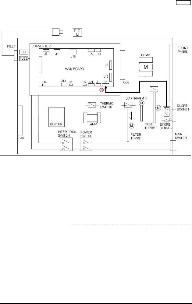
2-1 Power input failure
Incapable to input power 2-1-1 Block diagram
2-1-2 Estimated location of failure
No |
Estimated failure location |
|
Inspection method |
|
|
|
|||
|
|
|
|
|
|
|
|
|
|
|
Input voltage |
1 |
Verify the voltage of wall socket. |
|
|
|
|||
|
|
|
* Conformity with commercial power voltage standard. |
|
|
|
|||
|
|
|
|
|
|
|
|
Tester |
|
|
Power Cable |
1 |
Connect the Power Cable to wall socket and verify voltage at inlet side. |
||||||
|
|
|
* Conformity with commercial power voltage standard. |
|
|
|
|||
|
|
|
|
|
|
|
|
Tester |
|
|
Body Inlet Plug |
1 |
Confirm that the inlet plug is not bend or distorted. |
|
|
|
|||
|
|
|
|
|
Visual inspection |
|
|||
|
Fuse |
1 |
Confirm that the fuse was not burned out. |
|
|
|
|
|
|
|
|
|
|
|
|
|
|
Tester |
|
|
Power Switch |
1 |
Confirm that the Power Switch inside the equipment is pushed when |
||||||
|
|
|
the Main Switch on the Front Panel is pushed. |
|
|
|
|||
|
|
|
|
Visual |
Inspection |
|
|||
|
|
2 |
Confirm conductivity of the Power Switch when power |
is ON. |
|
|
|
||
|
|
|
|
|
|
|
|
Tester |
|
|
Interlock Switch |
1 |
Confirm that the switch is pushed by the Lamp Door. |
|
|
|
|||
|
|
|
|
Visual |
Inspection |
|
|||
|
|
2 |
Confirm conductivity of the Interlock Switch when power is ON. |
||||||
|
|
|
|
|
|
|
|
Tester |
|
|
|
|
|
|
|
Interlock Jig |
|
||
|
Flat Cable |
1 |
Verify connection of the Flat Cable |
|
|
|
|
||
|
|
|
Main Board (J12) <--> Front Panel |
Visual |
Inspection |
|
|||
|
|
|
|
|
|
|
|||
2-3
ISSUE1

|
|
|
Troubleshooting |
CLV-180 |
||
|
|
|
|
|||
|
Main Board |
1 |
Confirm that the input voltage to Main Board J16 is correct. |
|||
|
Converter |
|
J16 (Main Board) <- -> Converter) |
Tester |
|
|
|
|
|
|
|
||
|
|
|
1pin : DC +15V±0.75V |
|||
|
|
|
2pin : DC +12V±0.6V |
|||
|
|
|
3pin : DC + 5V±0.25V |
|||
|
|
|
4pin : GND |
|||
|
|
|
5pin : DC -15V±0.75V |
|||
|
|
|
YES → Replace Main Board |
|||
|
|
|
NO → Replace Converter |
|||
|
Power Switch LED |
1 |
Confirm that the Power Switch LED is lit: |
|||
|
|
|
NO → Replace the Power Switch LED |
|||
|
Front Panel Unit |
1 |
Confirm that the Front Panel of LED is lit: |
|||
|
|
|
NO → Replace the Front Panel |
|||
2-2 Lamp failure
Xenon Lamp of light source not lit 2-2-1 Block diagram
2-2-2 Estimated location of failure
|
No |
Estimated failure location |
|
Inspection method |
|
|
|
|
|
|
|
|
|
Power input failure |
|
Refer to 2-1 |
|
|
|
Emergency Lamp Malfunction |
|
Refer to 2-16 |
|
|
|
Panel malfunction |
|
Refer to 2-13 |
|
|
|
Thermo Switch / |
1 |
Status of Thermo Switch when buzzer is sounding |
|
|
|
Main Board |
|
Thermo Switch |
|
|
|
|
|
Less than 85 |
|
|
|
|
|
Conductive |
|
|
|
|
|
85 or higher |
|
|
|
|
|
Non-conductive |
|
|
|
|
|
Within standard -> Replace Main Board |
|
|
|
|
|
Out of standard -> Replace Thermo Switch |
|
|
|
|
|
|
|
|
|
|
|
|
|
|
ISSUE1 |
2-4 |
|
||
|
|
|
|
||

|
|
|
|
|
|
|
Troubleshooting |
CLV-180 |
|
|
|
|
|
|
|
|
|
||
|
|
|
|
|
|
|
|
||
|
Main Board |
1 |
Confirm that the signals in the Main Board are correct: |
||||||
|
|
|
Main Board J6/2Pin |
|
|
|
|
|
|
|
|
|
HIGH : XENON Lamp lit |
*HIGH : approx. 5 V |
|||||
|
|
|
LOW : XENON Lamp not lit |
|
|
|
|
|
|
|
|
|
H -> L when the Ignition Button is pushed ON to turn on Lamp |
||||||
|
|
|
L -> H when the Ignition Button is pushed OFF to turn off Lamp |
||||||
|
|
|
(Long push) |
|
|
|
|
|
|
|
|
|
NO → Replace Main Board |
|
|
|
|
|
|
|
Surrounding the Lamp |
1 |
Verify Lamp attachment. |
|
|
|
|
|
|
|
|
|
Confirm that Lamp is attached properly. |
||||||
|
|
|
Confirm that heat compound is applied properly. |
||||||
|
|
|
Confirm that the area surrounding the Xenon lamp contacts is clean. |
||||||
|
|
|
* Cleaning is required if the discoloration is found. |
||||||
|
|
2 |
Check the area surrounding the Lamp House. |
||||||
|
|
|
No unnecessary objects (e.g. metal chip) |
||||||
|
|
|
No leakage of high voltage pulse |
||||||
|
|
|
Check connection with Terminal F and Terminal R |
||||||
|
|
|
Confirm there is enough distance between Round Terminal and Lamp |
||||||
|
|
|
House |
|
|
|
|
|
|
|
Xenon Lamp / |
1 |
Clattering noise at ignition |
|
|
|
|
|
|
|
Igniter |
|
YES → Replace Xenon Lamp |
||||||
|
|
|
NO → Igniter |
|
|
|
|
|
|
|
Converter |
1 |
Xenon Lamp not lit even after procedures 1-7 |
||||||
|
|
|
YES → Replace Converter |
|
|
|
|
|
|
2-3 Lamp malfunction |
|
|
|
|
|
|
|
|
|
Lamp going out |
|
|
|
|
|
|
|
|
|
2-3-1 Estimated location of failure |
|
|
|
|
|
|
|
|
|
No |
Estimated location failure |
|
Inspection method |
||||||
|
|
|
|
|
|||||
|
Log |
1 |
Verify frequency of Lamp failure errors. |
||||||
|
|
|
* Refer to EVIS communication Checker for verification method. |
||||||
|
|
|
|
|
|
Evis communication checker |
|
||
|
|
|
|
|
CLV-180 Communication Cable |
|
|||
|
Power input failure |
|
Refer to 2-1 |
|
|
|
|
|
|
|
Emergency Lamp malfunction |
|
Refer to 2-16 |
|
|
|
|
|
|
|
Cooling Malfunction |
|
Refer to 2-6 |
|
|
|
|
|
|
|
Lamp failure |
|
Refer to 2-2 |
|
|
|
|
|
|
2-4 Scope connection failure |
|
|
|
|
|
|
|
|
|
Scope not mounting |
|
|
|
|
|
|
|
|
|
2-4-1 Estimated location of failure |
|
|
|
|
|
|
|
|
|
No |
Estimated location failure |
|
Inspection Metod |
||||||
|
|
|
|
||||||
|
Scope |
1 |
Confirm that Scope is a compatible one. |
||||||
|
Scope Socket |
1 |
Confirm that the Scope Socket is free of abnormalities. |
||||||
|
|
|
* Insert Heat Cover Positioning Jig to Scope Socket and confirm that |
||||||
|
|
|
it's not caught inside. |
|
|
|
|
|
|
|
|
|
|
|
|
|
Heat Cover Positioning Jig |
|
|
2-5
ISSUE1
Troubleshooting CLV-180
2-5 High-brightness malfunction
Not changing to high-brightness function mode 2-5-1 Block diagram
2-5-2 Estimated location of malfunction
No |
Estimated location failure |
|
Inspection Method |
||
|
|
|
|
|
|
|
High-brightness scope |
1 |
Confirm that scope is compatible for high-brightness. |
||
|
Panel malfunction |
|
Refer to 2-13 |
||
|
|||||
|
Scope Sensor / |
1 |
Confirm following status of J15 connector on Main Board when |
||
|
Main Board |
|
high-brightness scope is connected: |
||
|
|
|
Main Board J15 |
Tester |
|
|
|
|
|
|
|
|
|
|
When high-brightness scope is connected |
||
|
|
|
Pin 2: HIGH |
||
|
|
|
Pin 5: LOW |
||
|
|
|
Pin 8: LOW |
||
|
|
|
Pin 9: GND |
||
|
|
|
* HIGH: approx. 5 V |
||
|
|
|
YES → Replace Main Board |
||
|
|
|
NO → Replace Scope Sensor |
||
2-6
ISSUE1
 Loading...