


 Loading...
I . SAFETY GUIDE
II . SYSTEM OUTLINE & SPEC.
III . PACKING DETAILS CHECK
IV . OPERATION INSTRUCTIONS
V . TROUBLESHOOTING
VI. BACKPANEL SWITCH SETTINGS
CONFOCAL LASER SCANNING BIOLOGICAL MICROSCOPE
User’s Manual
FV5-LD405/440 FV5-LDPSU
Semiconductor Laser Head / Laser Power Supply Unit
Petition
Thank you for purchasing the system at this time. Please read this instruction manual carefully before using this system in order to get optimum performance of this system and also for safety considerations. This manual contains six sections – [SAFETY GUIDE], [SYSTEM OUTLINE & SPEC.], [PACKING DETAILS CHECK], [OPERATING INSTRUCTIONS],
[TROUBLESHOTTING] and [BACKPANEL SWTCH SETTINGS]. When using this system, put AX7332 this manual under your control and keep it carefully even if you read over.

Caution
1.This manual – part or whole, shall not be used or reproduced without permission.
2.Information in this manual is subject to change without notice.
Page 1

Manual configuration for this system
Manual configuration for this system
This manual comprises with six sections and describes the following articles respectively.
I.SAFETYGUIDE
This section describes requests, cautions and kinds of warning labels when using this system.
1 |
Safety considerations ........................................................................ |
I. |
1-1 |
2 |
Warning label .................................................................................................. |
I. |
2-1 |
3 |
Cautions when using the system .................................................................. |
I. |
3-1 |
4 USER’S SAFETY PROTECTION MEASURES ACCORDING TO |
|
|
|
|
IEC60825-1:1993+A1:1997+A2:2001 “LASER PRODUCT RADIATION SAFETY |
|
|
|
STANDARD” ................................................................................................. |
I. |
4-1 |
II.SYSTEMOUTLINE&SPEC.
This section describes outline of the system and specifications.
1 |
System outline ................................................................................................ |
II. |
1-1 |
2 |
Specifications ................................................................................................. |
II. |
2-1 |
3 |
Operating hours ............................................................................................. |
II. |
3-1 |
III. PACKING DETAILS CHECK
This section describes details of packing for this system.
1 |
Integration with this system .......................................................................... |
III. |
1-1 |
2 |
Packing details ............................................................................................... |
III. |
2-1 |
3 |
Setup .............................................................................................................. |
III. |
3-1 |
IV. OPERATION INSTRUCTIONS
This section describes operating method of this system.
1 |
Powering up and shutdown ........................................................................... |
IV. |
1-1 |
2 |
Laser emission ................................................................................................ |
IV. |
2-1 |
3 |
Laser intensity change .................................................................................... |
IV. |
3-1 |
2Page

Manual configuration for this system
4 Description of LED indicators ........................................................................ |
IV. 4-1 |
V. TROUBLESHOOTING
This section describes countermeasures to the troubles. |
|
|
1 Countermeasure when trouble occurs .......................................................... |
V. |
1-1 |
|
|
|
VI . BACK PANEL SWITCH SETTINGS |
|
|
|
|
|
This section describes back panel switch settings. |
|
|
1 Warning to back panel switch settings .......................................................... |
VI. |
1-1 |
Page 3

Book Conventions of this manual
Book Conventions of this manual
This manual describes each section, using the following book conventions.
Symbols for warning, caution and hint used
Conventions |
Description |
|
|
Indicates a warning to user to prevent injuries and or damage |
|
|
of products (including peripheral furniture’s) |
|
NOTE |
Indicates details of caution to prevent damage or deterioration |
|
of products. |
||
|
||
TIP |
Indicates a tip or hint. |
|
|
||
|
|
4Page

I. SAFETY GUIDE
Note for this section
This section describes cautions in order to use this system safely. Please read this section for sure before using the system.
 System may not be guaranteed when it is used with other methods than described in this manual. Unless instructions are observed, more trouble may occur. Please use this system in accordance with this manual.

|
|
|
|
|
CONTENTS |
|
|
|
|
|
|
|
|
1 |
Safety Considerations |
|
1-1 |
|
||
2 |
Warning label |
2-1 |
||||
|
|
2-1 |
Label related to laser safety ........................................................... |
2-1 |
|
|
|
|
|
2-1-1 Warning label................................................................................................. |
2-1 |
|
|
|
|
|
2-1-2 Aperture label ................................................................................................ |
2-2 |
|
|
|
|
|
2-1-3 Protective housing label ................................................................................ |
2-4 |
|
|
3 |
Cautions when using the system |
3-1 |
||||
|
|
3-1 About system move......................................................................... |
3-1 |
|
||
|
|
3-2 |
Caution when using ........................................................................ |
3-1 |
||
|
|
3-3 |
Caution ............................................................................................. |
3-1 |
||
4 USER’S SAFETY PROTECTION MEASURES ACCORDING TO IEC60825-1:1993+A1:1997+A2:2001 “LASER PRODUCT RADIATION SAFETY STANDARD”4-1
Regarding DIP switches at back panel of FV5-LDPSU, see VI – 1 
[Warning to back panel switch settings].
Safety Considerations
1 Safety Considerations
This system designates the use of laser products of the following class.
In case of FV5-LD405
CLASS III b(CDRH)
CLASS 3B IEC60825-1:1993+A1:1997+A2:2001
EN60825-1: 1994+A11:1996+A2:2001
JIS C6802: 997+A1:1998
In case of FV5-LD440
CLASS III b(CDRH)
CLASS 3B IEC60825-1:1993+A1:1997+A2:2001
EN60825-1: 1994+A11:1996+A2:2001
JIS C6802: 1997+A1:1998
Laser products of class 3B can only be used under control of laser safety officer. Before using laser products, refer to Chapter 4 – “USER’S SAFETY PROTECTION MEASURES ACCORDING TO IEC60825- 1:1993+A1:1997+A2:2001 “LASER PRODUCT RADIATION SAFETY STANDARD”, and exercise adequate countermeasures and then, use the laser products. Should you have any open question, contact our local sales office.
Caution when using
Pay your utmost attention to the following points.
When red LED’s of LASER EMISSION on FV5-LDPSU are lighting, it indicates that laser is being emitted. When microscope is connected, the laser is emitted from objective tip. Reflection may enter your eyes or light may be scattered around. Care must be taken in this case. In addition, do not see the sample while laser is scanning. 
When two red LED’s are lighting, it means “laser emission”.
I. SAFETY GUIDE
Page I . 1 - 1

Safety Considerations
Regarding settings of DIP switches located at back panel of FV5-LDPSU, refer to VI 1 – 
Back panel switch settings.
zSet this system on robust base.
zThis system generates heat. When installing this system, make it sure that a space of 10cm or more is provided, left and right of the system, and do not block vent openings.
zPower cable may be molten when it hits hot place of lamp housing. When installing, make it sure that the power cable is adequately apart from the lamp housing.
zNever insert a metal piece into vent opening as it may cause failure or electric shock.
zDo not apply your hand or finger to laser beam that comes from mounting hole of objective lens or objective tip.
If your hand or finger is exposed to laser beam, it may cause a skin hazard. In addition, never insert a mirror into light path as the laser beam may come outside and it may enter your eye which is very dangerous
zDo not set or remove the sample during laser emission (laser scanning). If you set or remove the sample in such a case, reflection from the sample may enter your eye which is very dangerous. Moreover, do not look at the sample during laser emission (laser scanning).
zSystem performance as well as system safety cannot be guaranteed in case that cover is detached or the system is disassembled with use of tools. Never disassemble the system.
zDo not bend or pull fiber excessively. Do not step on the fiber. If the fiber is broken, laser beam may leak which is very dangerous. In case that such unlikely event occurred, turn power of laser power supply unit to OFF position immediately and contact our sales office. (when using FV5-LD405 only)
zAlways use the power cord provided by Olympus. If no power cord is provided, please select the proper power cord by referring to the section “PROPER SELECTION OF THE POWER SUPPLY CORD ”at the end of this instruction manual.
I. SAFETY GUIDE
I . 1 - 2 Page

Safety Considerations
zConnect the power cord correctly and ensure that the ground terminal of the power supply and that of the wall outlet are properly connected. If the equipment is not grounded, Olympus can no longer warrant the electrical safety and performance of the equipment.
zBefore connecting cord and cable, verify that the main switch is turned to O – (OFF) position.
zMixture (alcohol (3): ether (7)) that is used for cleaning optics is high inflammable so that utmost care must be taken when handling with respect to fire and main switch ON/OFF. When using ether, it is recommended that the room is well-ventilated.
zBe careful so as not to apply any excessive force to connecting cord or cable as it is very weak against bend or twist.
zDo not change fuses that are located above the power cord connector. When change of fuses is required, contact and consult with our local sales office.
zDo not carry the semiconductor laser head by hand. It may be damaged as it is very delicate tool.
zDo not swing around fiber carelessly. If fiber being emitted is swung around, laser beam may hit human body that would cause a hazard. (when using FV5-LD405 ONLY)
zWhen you dispose of this system, it is necessary to handle it as an industrial waste. In case that you cannot dispose it yourself, deliver it to our local sales office.
I. SAFETY GUIDE
Page I . 1 - 3

Safety Considerations
zExternal remote control connector is provided.
(Rating of external remote interlock circuit: Rated current 0.3A, Rated voltage 5V)
When shipping, a short pin of interlock connector is provided. Instead of the short pin, the external remote interlock circuit can be connected. For further details, see Chapter 4 - USER’S SAFETY PROTECTION MEASURES ACCORDING TO IEC60825-1:1993+A1:1997+A2:2001 “LASER PRODUCT RADIATION SAFETY STANDARD”.
When using remote interlock connector, contact our local sales office for sure 
as it may cause electric shock or fire.
Remote interlock connector of this system
zSee also instruction manual for microscope regarding safety considerations.
Symbols related to safety
This system is attached with the following marks.
Understand the meaning of symbols and handle the system safely.
Symbol |
Meaning |
|
|
|
Before using, read instruction manual for sure. |
|
|
In case of error handling, user may get hazard or products may be damaged. |
|
|
|
|
|
Laser beam is used. Pay utmost care to handling. |
|
|
|
|
|
Main switch is turned ON. |
|
|
|
|
|
|
|
|
|
|
|
Main switch is turned OFF. |
|
|
|
I. SAFETY GUIDE
I . 1 - 4 Page

Warning label / Label related to laser safety
2 Warning label
2-1 Label related to laser safety
Warning is displayed at the place where a care must be paid in handling and operating the system. Exercise the instruction for sure. When label is blurred or peeled off, contact our local sales office and ask if new label for change is available.
2-1-1 Warning label
The warning label shown below is attached to the system.
(In case of FV5-LD405) |
(In case of FV5-LD440) |
Place attached
Warning label is attached.
(In case of FV5-LD405) |
(In case of FV5-LD440) |
In case that you purchase our FV5-FUR405, our service personnel would attach manipulator cover to it.
I. SAFETY GUIDE
Page I . 2 - 1

Warning label / Label related to laser safety
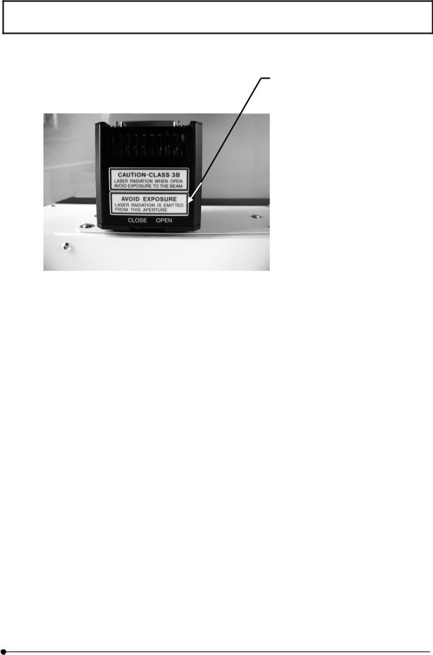
2-1-2 Aperture label
Aperture label shown below is attached to the system.
Place attached
Aperture label is attached.
(In case of FV5-LD405)
In case that you purchase our FV5FUR405, our service personnel would attach manipulator cover to it.
Aperture label is attached.
The case where the shutter is open and the fiber cable disconnected.
Laser beam comes out here.
(In case of FV5-LD405)
I. SAFETY GUIDE
I . 2 - 2 Page
Warning label / Label related to laser safety
Opening label is attached.
(In case of FV5-LD440)
I. SAFETY GUIDE
Page I . 2 - 3

Warning label / Label related to laser safety
2-1-3 Protective housing label
Protective housing label as shown below is attached to the system.
Place attached
Protective housing label is attached.
(In case of FV5-LD405)
In case that you purchase our FV5-FUR405, our service personnel would attach manipulator cover to it.
The case where the shutter is open and the fiber cable disconnected.
I. SAFETY GUIDE
I . 2 - 4 Page

Warning label / Label related to laser safety
Protective housing label is attached.
(In case of FV5-LD440)
Protective housing label may be attached to the place other than the place shown in this manual. It is a warning label for our service personnel.
When label is blurred or peeled off, contact our local sales office for availability of label  for change.
I. SAFETY GUIDE
Page I . 2 - 5
Cautions when using the system
3 Cautions when using the system
3-1 About system move
zAssembling and setup of this system are executed by our service parsonnel. Avoid move of the system as it may put optics system out of order. When the move of this system is required, contact and consult with our local sales office. In an event of disorder or breakage of the system due to the move by customer, we hold no responsibility.
3-2 Caution when using
zHandle this system with utmost care in order not to give a shock as it is precision instrument.
zDo not bend, pull or step on fiber excessively. Performance would severely be deteriorated. (when using FV5-LD405 only).
zPower cable is also used to stop power supply against unlikely event. Power cable connector (located at back panel of FV5-LDPSU) or power consent should be within a reach of your hand. Set the power supply unit at the place where you can remove power cable easily against unlikely event. However, do not remove it during power supply except emergency situation.
zDo not move the system by pulling power cable.
zFor environment condition of usage, see II Chapter 2 – Specifications.
zWhen you clean each section, use soft cloth that contains diluted mild detergent and wipe out gently. Do not use organic solvent as it would deteriorate paint or plastic parts.
3-3 Caution
Safety may not be guaranteed if the system is used by other methods than those described in this manual and
failure may occur. Use this system in accordance with this manual.
I. SAFETY GUIDE
Page I . 3 - 1

USER’S SAFETY PROTECTION MEASURES ACCORDING TO IEC60825-
1:1993+A1:1997+A2:2001 “LASER PRODUCT RADIATION SAFETY STANDARD”
4 USER’S SAFETY PROTECTION MEASURES ACCORDING TO IEC60825-1:1993+A1:1997+A2:2001 “LASER PRODUCT RADIATION SAFETY STANDARD”
IEC60825-1:1993+A1:1997+A2:2001 requires the users of laser products to take proper safety protection measures (summarized below). When using this system, be sure to take proper measures regarding the following points.
For details, please refer to the IEC60825-1:1993+A1:1997+A2:2001 mentioned above.
For warning labels used with this system and their positions, see Section 2, “Warning Labels” of this manual.
This requirement does not apply to Class 3B laser products with not more than five times the AEL of Class 2 in the wavelength range from 400 nm to 700 nm.
I. SAFETY GUIDE
Page |
I . 4 - 1 |

USER’S SAFETY PROTECTION MEASURES ACCORDING TO IEC60825- 1:1993+A1:1997+A2:2001 “LASER PRODUCT RADIATION SAFETY STANDARD”
NOTE 1 There is only limited evidence about effects for exposures of less than 10-9s for wavelengths less than 400 nm and greater than 1400 nm. The AELs for these exposure times and wavelengths have been derived by calculating the equivalent radiant power or irradiance from the radiant power or radiant exposure applying at 10-9s for wavelengths less than 400 nm and greater than 1400 nm.
NOTE 2 Correction factors C1 to C7 and breakpoints T1 and T2 used in tables 1 to 4 are defined in the following expressions and are illustrated in figures 1 to 8.
Parameter |
Spectral region |
Figures |
|
|
|
C1 = 5,6 x 10³t0,25 |
302,5 to 400 |
1 |
T1 = 100,8(nj-295) x 10-15s |
302,5 to 315 |
2 |
C2 = 100,2(nj-265) |
302,5 to 315 |
3 |
T2 = 10 x 10[(ǂ –ǂmin)/98,5]sa |
400 to 1400 |
4 |
C3 = 1,0 |
400 to 450 |
5 |
|
|
|
C3 = 100,02(nj-450) |
450 to 600 |
5 |
C4 = 100,002(nj-700) |
700 to 1050 |
6 |
C4 = 5 |
1050 to 1400 |
6 |
|
|
|
C5 = 10-1/4 b |
400 to 106 |
7 |
C6 = 1 for ǂ ǂmin |
400 to 1400 |
c |
|
||
C6 = ǂ/ǂmin for ǂmin < ǂ ǂmax |
400 to 1400 |
c |
|
||
C6 = ǂmax/ǂmin = 66,7 for ǂ > ǂmind |
400 to 1400 |
c |
C7 = 1 |
700 to 1150 |
8 |
|
|
|
C7 = 100,018(nj-1150) |
1150 to 1200 |
8 |
C7 = 8 |
1200 to 1400 |
8 |
|
|
|
aT2 = 10 s for ǂ < 1,5 mrad and T2 = 100 s for ǂ > 100 mrad
bC5 is only applicable o pulse durations shorter than 0,25 s.
cC6 is only applicable to pulsed lasers and to CW lasers where thermal injury dominates (see table 1)
dThe limiting angle of acceptance  p shall be equal to ǂmax
ǂmin = 1,5 mrad
ǂmax = 100 mrad
N is the number of pulses contained within the applicable duration (see 8.4f) and 13.3)
NOTE 3 See table 7 for limiting apertures.
NOTE 4 In the formulae in the tables 1 to 4 and in these notes, the wavelength has to be expressed in nanometres, the emission duration t has to be expressed in seconds and ǂ has to be expressed in milliradians.
I. SAFETY GUIDE
I . 4 - 2 |
Page |

USER’S SAFETY PROTECTION MEASURES ACCORDING TO IEC60825-
1:1993+A1:1997+A2:2001 “LASER PRODUCT RADIATION SAFETY STANDARD”
10 Safety precautions
10.1General
This section specifies safety precautions and control measures to be taken by the user of a laser product, in accordance with its hazard classification. Often users can use the manufacturer's classification of the product for classification of the laser installation, thus avoiding all measurements. This section is supplied for the user's information. Nothing in this section shall be considered as constraints or requirements imposed upon the manufacturer. For installations where Class 3R laser products emitting energy outside of the 400nm to 700nm wavelength range or Class 3B or Class 4 laser products are operated, a laser safety officer should be appointed. It should be the laser safety officer’s responsibility to review the following precautions and designate the appropriate controls to be implemented. If should be the laser safety officer's responsibility to review the following precautions and designate the appropriate controls to be implemented. Wherever practicable, laser protective enclosures should be used for lasers of Class 3B or Class 4. Warning labels should be placed upon removable parts of protective enclosures or at service connections where a hazard is introduced by their removal or by disconnection.
The purpose of safety precautions and control measures is to reduce the possibility of exposure to hazardous levels of laser radiation, and to other associated hazards. Therefore, it may not be necessary to implement all of the control measures given. Whenever the application of any one or more control measures reduces the possible exposure to a level at or below the applicable MPE, then the application of additional control measures should not be necessary.
If a user modification of a previously classified laser product affects any aspect of the product's performance or intended functions within the scope of this standard, the person or organization performing any such modification is responsible for ensuring the reclassification and relabelling of the laser product.
I. SAFETY GUIDE
Page |
I . 4 - 3 |

USER’S SAFETY PROTECTION MEASURES ACCORDING TO IEC60825- 1:1993+A1:1997+A2:2001 “LASER PRODUCT RADIATION SAFETY STANDARD”
10.2Use of remote interlock connector
The remote interlock connector of Class 3B and Class 4 lasers should be connected to an emergency master disconnect interlock or to room, door or fixture interlocks (see 4.4).
The person in charge may be permitted momentary override of the remote interlock connector to allow access to other authorized persons if it is clearly evident that there is no optical radiation hazard at the time and point of entry.
10.3Key control
Class 3B and Class 4 laser products not in use should be protected against unauthorized use by removal of the key from the key control (see 4.5).
10.4Beam stop or attenuator
The inadvertent exposure of bystanders to laser radiation from Class 3B or Class 4 laser products should be prevented by the use of the beam attenuator or beam stop (see 4.7).
10.5Warning signs
The entrances to areas or protective enclosures containing Class 3B and Class 4 laser products should be posted with appropriate warning signs.
I. SAFETY GUIDE
I . 4 - 4 |
Page |

USER’S SAFETY PROTECTION MEASURES ACCORDING TO IEC60825-
1:1993+A1:1997+A2:2001 “LASER PRODUCT RADIATION SAFETY STANDARD”
10.6Beam paths
The beam emitted by each Class 1M and Class 2M laser product classified under condition 1 of table 10, each Class 3R laser product emitting energy outside of the 400nm to 700nm wavelength range, and each Class 3B or Class 4 laser product should be terminated at the end of its useful path by a diffusely reflecting material of appropriate reflectivity and thermal properties or by absorbers.
Open laser beam paths should be located above or below eye level where practicable.
The beam paths of Class 3R laser products emitting energy outside of the 400nm to 700nm wavelength range and Class 3B or 4 laser products should be as short as practicable, should have a minimum number of directional changes, should avoid crossing walkways and other access routes, and should, where practicable, be enclosed. The beam enclosure (for example, a tube) should be securely mounted but preferably not rigidly attached to (or provide support for) beam-forming components.
I. SAFETY GUIDE
Page |
I . 4 - 5 |

USER’S SAFETY PROTECTION MEASURES ACCORDING TO IEC60825- 1:1993+A1:1997+A2:2001 “LASER PRODUCT RADIATION SAFETY STANDARD”
10.7Specular reflections
Care should be exercised to prevent the unintentional specular reflection of radiation from Class 3R, Class 3B or Class 4 laser products. Mirrors, lenses and beam splitters should be rigidly mounted and should be subject to only controlled movements while the laser is emitting.
Care should be exercised to prevent the unintentional specular reflection of radiation from Class 1M and Class 2M laser products from surfaces that may focus the beam.
Reflecting surfaces that appear to be diffuse may actually reflect a considerable part of the radiation beam specularly, especially in the infra-red spectral range. This may be potentially hazardous for longer distances than one would expect for purely (Lambertian) diffuse reflections.
Special care needs to be taken in the selection of optical components for Class 3B and Class 4 lasers and in maintaining the cleanliness of their surfaces.
Potentially hazardous specular reflections occur at all surfaces of transmissive optical components such as lenses, prisms, windows and beam splitters.
Potentially hazardous radiation can also be transmitted through some reflective optical components such as mirrors (for example, infra-red radiation passing through a reflector of visible radiation).
I. SAFETY GUIDE
I . 4 - 6 |
Page |
Loading...