


INSTRUCTIONS
CX31
BIOLOGICAL MICROSCOPE
This instruction manual is for the Olympus Biological Microscope Model CX31. To ensure the safety, obtain optimum performance and to familiarize yourself fully with the use of this microscope, we recommend that you study this manual thoroughly before operating the microscope. Retain this instruction manual in an easily accessible place near the work desk for future reference.
A X 6 6 5 4

CX31
CONTENTS
Page
IMPORTANT — Be sure to read this section for safe use of the equipment. — 1-3
1 |
NOMENCLATURE |
4 |
|
|
|
2 |
SUMMARY OF BRIGHTFIELD OBSERVATION PROCEDURE |
5 |
|
|
|
3ASSEMBLY — See this section for the replacement of the light bulb. — 6-7
4 USING THE CONTROLS |
8-14 |
4-1 Base.......................................................................................................................................................................................... |
8 |
1 Turning On the Bulb |
2 |
Field Iris Diaphragm |
4-2 Focusing Block............................................................................................................................................................... |
9 |
1 Adjusting the Coarse Adjustment Knob Tension |
2 Simplified Pre-focusing Dial |
4-3 Stage.............................................................................................................................................................................. |
10-11 |
1 |
Placing the Specimen |
2 |
Moving the Specimen |
4-4 Observation Tube................................................................................................................................................ |
11-12 |
1 |
Adjusting the Interpupillar Distance |
4 |
Using the Eye Shades |
2 |
Adjusting the Tilt |
3 Adjusting the Diopter |
5 |
Using the Eyepiece Micrometer Disk |
|
4-5 Condenser........................................................................................................................................................................ |
13 |
1 Centering the Field Iris Diaphragm |
2
 Aperture Iris Diaphragm
4-6 Immersion Objectives............................................................................................................................................ |
14 |
1
 Using the Immersion Objectives
5 |
TROUBLESHOOTING GUIDE |
15-16 |
6 |
SPECIFICATIONS |
17 |
7 |
OPTICAL CHARACTERISTICS |
18 |
|
PROPER SELECTION OF THE POWER SUPPLY CORD.................................................. |
19-20 |
IMPORTANT
 SAFETY PRECAUTIONS
1. After the equipment has been used in an observation of a specimen that is accompanied with a potential of infection, clean the parts coming in contact with the specimen to prevent infection.
· Moving this product is accompanied with the risk of dropping the specimen. Be sure to remove the specimen before moving this product.
· In case the specimen is damaged by erroneous operation, promptly take the infection prevention measures.
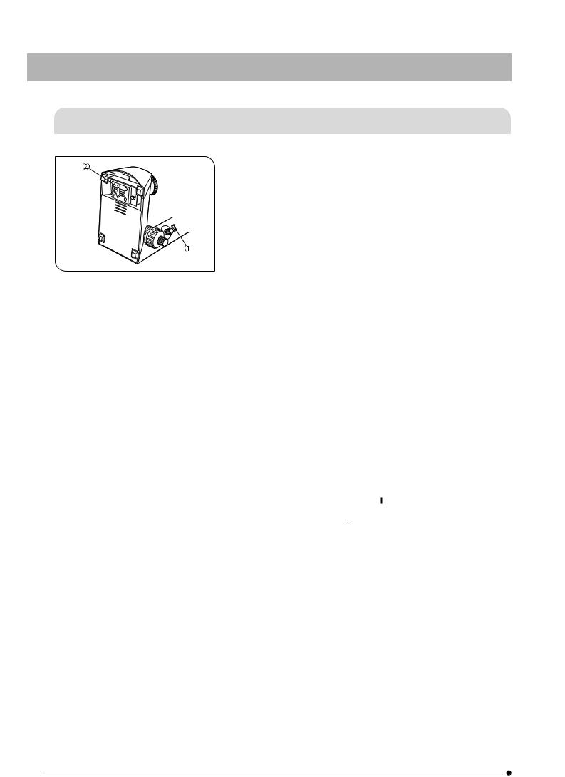
2. To avoid potential shock hazard and fire, always set the main switch @ to “ ” (OFF) and disconnect the power cord from the AC receptacle
at the rear of the microscope and from the wall outlet before replacing
Fig.1
the bulb. Allow the lamp housing cover ² and the bulb to cool before touching them.
3.Install the microscope on a sturdy, level table.
The air vents on the underside of the base should never be blocked by placing the microscope on a flexible surface such as a carpet, as this could result in overheating and cause a fire.
4.Always use the power cord provided by Olympus. If no power cord is provided, please select the proper power cord by referring to the section “PROPER SELECTION OF THE POWER SUPPLY CORD” at the end of this instruction manual. If the proper power cord is not used, Olympus can no longer warrant the electrical safety and performance of the equipment.
5.When installing the microscope, route the power cord away from the microscope base. Should the power cord come in contact with the hot microscope base, the power cord could melt and cause electric shock.
6.Connect the power cord correctly and ensure that the grounding terminal of the power supply and that of the wall outlet are properly connected. If the equipment is not grounded, Olympus can no longer warrant the electrical safety and performance of the equipment.
7.Never set the main switch @ to “ ” (ON) while any metallic object is inserted into the air vents of the microscope frame as this will result in electrical shock, personal injury and equipment damage.
8.When the microscope is not in use or when it is malfunctioning, disconnect the power cord plug from the AC receptacle or from the wall outlet.
1

CX31
Safety Symbols
The following symbols are found on the microscope. Study the meaning of the symbols and always use the equipment in the safest possible manner.
Symbol |
Explanation |
|
|
Indicates that the surface becomes hot, and should not be touched with bare hands.
Before use, carefully read the instruction manual. Improper handling could result in personal injury to the user and/or damage to the equipment.
Indicates that the main switch is ON.
Indicates that the main switch is OFF.
Warning Label
A warning label is affixed at parts where special precaution is required when handling and using the microscope. Always heed the warnings.
Warning label |
Base underside |
position: |
(Caution for bulb replacement) |
|
|
If the warning label becomes soiled, peeled off, etc., contact Olympus to have it replaced.
1Getting Ready
|
1. A microscope is a precision instrument. Handle it with care and avoid |
|
subjecting it to sudden or severe impact. |
|
2. Do not use the microscope where it is subjected to direct sunlight, |
|
high temperature and humidity, dust or vibrations. (For the operating |
|
environment conditions, refer to and adhere to the conditions specified |
|
in Chapter 6, “SPECIFICATIONS” on page 17.) |
|
3. The tension of the coarse focus adjustment knob should only be |
|
adjusted by means of the tension adjustment ring. |
|
4. Heat from the microscope is led away by natural convection. |
|
Consequently, leave an enough space (10 cm or more) on the rear of |
Fig. 2 |
the microscope and ensure that the room is well ventilated. |
5.When moving the microscope, carefully carry it with one hand under the base @ and the other hand holding at the recessed handle on the
rear of the arm ² as shown in the illustration on the left.
#Damage to the microscope will occur if you hold it by the stage, X- axis/Y-axis knob, binocular section of the observation tube, etc. Also be sure to remove the specimen to prevent it from falling off.
#Sliding the microscope on the surface of the table may damage or tear off the rubber feet and/or scratch the table top surface.
2

1Maintenance and Storage
1.Clean all glass components by wiping gently with gauze. To remove fingerprints or oil smudges, wipe with gauze slightly moistened with a mixture of ether (70%) and alcohol (30%).
 Since solvents such as ether and alcohol are highly flammable, they must be handled carefully. Be sure to keep these chemicals away from open flames or potential sources of electrical sparks -- for example, electrical equipment that is being switched on or off. Also remember to always use these chemicals only in a well-ventilated room.
2.Do not attempt to use organic solvents to clean the non-optical components of the microscope. To clean them, use a lint-free, soft cloth lightly moistened with a diluted neutral detergent.
3.Do not disassemble any part of the microscope as malfunction or damage may occur.
4.When not using the microscope, ensure that the frame is cooled down and store it in a locker or cover it with a dust cover.
5.When disposing of the microscope, check the regulations and rules of your local goverment and be sure to observe them.
3Caution
If the microscope is used in a manner not specified by this manual, the safety of the user may be imperiled. In addition, the equipment may also be damaged. Always use the equipment as outlined in this instruction manual.
The following symbols are used to set off text in this instruction manual.
 : Indicates that failure to follow the instructions in the warning could result in bodily harm to the user and/or damage to equipment (including objects in the vicinity of the equipment).
# : Indicates that failure to follow the instructions could result in damage to equipment. } : Indicates commentary (for ease of operation and maintenance).
This device complies with the requirements of directive 98/79/EC concerning in vitro diagnostic medical devices. CE marking means the conformity to the directive.
NOTE : This equipment has been tested and found to comply with the limits for a Class A digital device, pursuant to Part 15 of the FCC Rules. These limits are designed to provide reasonable protection against harmful interference when the equipment is operated in a commercial environment. This equipment generates, uses, and can radiate radio frequency energy and, if not installed and used in accordance with the instruction manual, may cause harmful interference to radio communications. Operation of this equipment in a residential area is likely to cause harmful interference in which case the user will be required to correct the interference at his own expense.
FCC WARNING : Changes or modifications not expressly approved by the party responsible for compliance could void the user's authority to operate the equipment.
3

CX31
NOMENCLATURE
}The revolving nosepiece is fastened with a band to prevent it from turning during transportation. Remove the band when unpacking the microscope. Be sure to store the band for re-transportation of the microscope.
* The stage is shipped with the two transport pins locked. When using the microscope for the first time, remove the transport lock pins before use.
}If you have not yet attached the lamp bulb and power cord to the microscope, read Chapter 3, “ASSEMBLY” on pages 6 to 7.
Eyepieces
(Fixed at 10X)
Diopter adjustment ring (Page 11)
Revolving Nosepiece
Objective
Specimen holder (Page 10)
Transport lock pin*
Aperture iris diaphragm knob (Page 13)
Condenser centering screws (Page 13)
Condenser
Filter holder
Place a 45 mm filter on this.
Field iris diaphragm ring
Interpupillar distance scale (Page 11)
Observation Tube
Binocular tube: CX31RBSF microscope frame
|
CX31RBSFA microscope frame |
Tilting tube: |
CX31RTBISF microscope frame |
|
Tube clamping screw |
(Use the provided Allen wrench.)
Simplified pre-focusing dial (Page 9)
Microscope Frame
CX31RBSF
CX31RBSFA
CX31RTBISF
Transport lock pin*
Main switch (Page 8)
Light intensity control knob (Page 8)
Stage
Fine focus adjustment knob (Page 9)
Coarse focus adjustment knob (Page 9)
X-axis knob (Page 11)
Y-axis knob (Page 11)
4

SUMMARY OF BRIGHTFIELD OBSERVATION
PROCEDURE
|
|
1 |
|
2 |
3 |
|
|
|
|
|||||||||||||
|
|
|
|
|
|
|
|
|
|
|
|
|
|
|
|
|
|
|
|
|
|
|
|
|
|
|
|
|
|
|
|
|
|
|
|
|
|
|
|
|
|
|
|
|
|
|
|
|
|
|
|
|
|
|
|
|
|
|
|
|
|
|
|
|
|
|
|
|
|
|
|
|
|
|
|
|
|
|
|
|
|
|
|
|
|
|
|
|
|
|
|
|
|
|
|
|
|
|
|
|
|
|
|
|
|
|
|
|
|
|
|
|
|
|
|
|
|
|
|
|
|
|
|
|
|
|
|
|
|
|
|
|
|
|
|
|
|
|
|
|
|
|
|
|
|
|
|
|
|
|
|
|
|
|
|
|
|
|
|
|
|
|
|
|
|
|
|
|
|
|
|
|
|
|
|
|
|
|
|
|
|
|
|
· Turn the revolving nosepiece to |
· Place a specimen on the stage. |
· Turn the X-axis knob and Y-axis |
|||
engage the 10X objective. |
(Page 10) |
knob to move the specimen into |
|||
#Make sure that the revolving |
|
the light path. (Page 11) |
|||
nosepiece stops with an audible |
|
|
|||
click. |
|
|
|||
4 |
|
5 |
6 |
||
|
|
|
|
|
|
|
|
|
|
|
|
|
|
|
|
|
|
|
|
|
|
|
|
·Set the main switch to “ I ” (ON) and adjust the brightness with the light intensity knob. (Page 8)
· Turn the coarse and fine |
· Adjust the interpupillary distance. |
adjustment knobs to bring the |
(Page 11) |
specimen into focus. |
· When the tilting observation tube is |
|
used, adjust the angle of tilt. |
|
(Page 11) |
7 |
8 |
9 |
· Adjust the diopter. (Page 11) |
· Center the field iris diaphragm. |
· Adjust the aperture iris diaphragm |
|
(Page 13) |
and field iris diaphragm. (Page 8) |
10
11
12
Engage the objective to be used for observation in the light path, then readjust the focus.
Place the required filter on the filter holder.
Re-adjust the aperture iris diaphragm, field iris diaphragm and brightness and start observation.
5
 Loading...