


INSTRUCTIONS
CX41
SYSTEM MICROSCOPE
This instruction manual is for the Olympus System Microscope Model CX41. To ensure the safety, obtain optimum performance and to familiarize yourself fully with the use of this microscope, we recommend that you study this manual thoroughly before operating the microscope. Retain this instruction manual in an easily accessible place near the work desk for future reference.
A X 7 2 5 5

CX41
CONTENTS
Correct assembly and adjustments are critical for the microscope to exhibit its full performance. If you are going to assemble the microscope yourself, please read Chapter 7, “ASSEMBLY” (pages 21 to 24) carefully.
Page
IMPORTANT — Be sure to read this section for safe use of the equipment. — 1-3
1 |
NOMENCLATURE |
4 |
2 |
SUMMARY OF BRIGHTFIELD OBSERVATION PROCEDURE |
5-6 |
3 |
USING THE CONTROLS |
7-16 |
|
3-1 Base.......................................................................................................................................................................................... |
7 |
1
 Turning On the Bulb
2 |
Field Iris Diaphragm |
3 Dummy Slider |
3-2 Focusing Block................................................................................................................................................................ |
8 |
1 Adjusting the Coarse Adjustment Knob Tension |
2 Pre-focusing Lever |
3-3 Stage................................................................................................................................................................................. |
9-10 |
1
 Placing the Specimen
2 |
Moving the Specimen |
3-4 Observation Tube................................................................................................................................................ |
10-12 |
1 |
Adjusting the Interpupillar Distance |
4 |
Using the Eye Shades |
6 |
Photomicrography/TV Observation |
2 |
Adjusting the Tilt |
3 Adjusting the Diopter |
5 |
Light Intensity Ratio of Trinocular Tube U-CTR30-2 |
|
7 |
Using the Eyepiece Micrometer Disk |
|
3-5 Condenser................................................................................................................................................................. |
12-14 |
1 |
Centering the Field Iris Diaphragm |
2 |
Aperture Iris Diaphragm |
3 |
Using Filters |
4 |
Using Darkfield Ring CH2-DS |
5 |
Using Low-Power Light Adjustment Objective CX-LA |
||
6 |
Compatibility of Option Units and Condensers |
||
|
3-6 Immersion Objectives............................................................................................................................................ |
15 |
|
3-7 Simplified Phase Contrast Ring Slits CX-PH1/PH2/PH3....................................................... |
16 |
4 |
TROUBLESHOOTING GUIDE |
17-18 |
5 |
SPECIFICATIONS |
19 |
6 |
OPTICAL CHARACTERISTICS |
20 |
7ASSEMBLY — See this section for the replacement of the light bulb. — 21-24
|
....................................................PROPER SELECTION OF THE POWER SUPPLY CORD |
25-26 |
IMPORTANT
This microscope employs a UIS (Universal Infinity System) optical design, and should be used only with UIS eyepieces, objectives and condensers, etc. (Other modules described on page 21 may also be usable with this microscope. For details, please consult Olympus or the catalogue.) Less than optimum performance may result if inappropriate accessories are used.
 SAFETY PRECAUTIONS
1.After the equipment has been used in an observation of a specimen that is accompanied with a potential of infection, clean the parts coming in contact with the specimen to prevent infection.
|
· Moving this product is accompanied with the risk of dropping the |
|
|
specimen. Be sure to remove the specimen before moving this |
|
|
product. |
|
|
· In case the specimen is damaged by erroneous operation, promptly |
|
|
take the infection prevention measures. |
|
|
· The product becomes unstable if its height is increased by an |
|
|
accessory mounted on it. In this case, take anti-topping measures to |
|
Fig. 1 |
prevent the specimen from being dropped when the product topples |
|
down. |
||
|
||
|
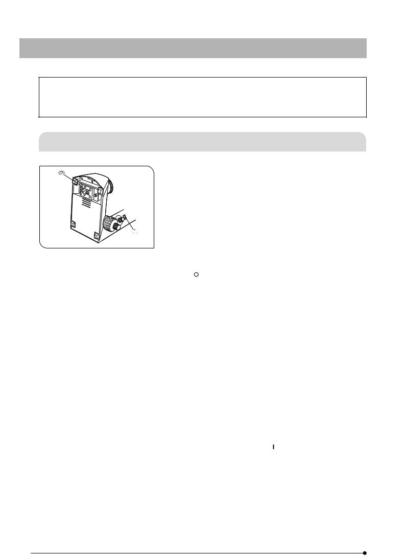
2. To avoid potential shock hazard and fire, always set the main switch @ |
|
|
to “ ” (OFF) and disconnect the power cord from the AC receptacle |
|
|
at the rear of the microscope and from the wall outlet before replacing |
|
|
the bulb. Allow the lamp housing cover ² and the bulb to cool before |
|
|
touching them. |
3.Install the microscope on a sturdy, level table.
The air vents on the underside of the base should never be blocked by placing the microscope on a flexible surface such as a carpet, as this could result in overheating and cause a fire.
4.Always use the power cord provided by Olympus. If no power cord is provided, please select the proper power cord by referring to the section “PROPER SELECTION OF THE POWER SUPPLY CORD” at the end of this instruction manual. If the proper power cord is not used, Olympus can no longer warrant the electrical safety and performance of the equipment.
5.When installing the microscope, route the power cord away from the microscope base. Should the power cord come in contact with the hot microscope base, the power cord could melt and cause electric shock.
6.Connect the power cord correctly and ensure that the grounding terminal of the power supply and that of the wall outlet are properly connected. If the equipment is not grounded, Olympus can no longer warrant the electrical safety and performance of the equipment.
7.Never set the main switch @ to “ ” (ON) while any metallic object is inserted into the air vents of the microscope frame as this will result in electrical shock, personal injury and equipment damage.
8.When the microscope is not in use or when it is malfunctioning, disconnect the power cord plug from the AC receptacle or from the wall outlet.
1
CX41
Safety Symbols
The following symbols are found on the microscope. Study the meaning of the symbols and always use the equipment in the safest possible manner.
Symbol |
Explanation |
|
|
IIndicates that the surface becomes hot, and should not be touched with bare hands.
Before use, carefully read the instruction manual. Improper handling could result in personal injury to the user and/or damage to the equipment.
Indicates that the main switch is ON.
Indicates that the main switch is OFF.
Warning Label
A warning label is affixed at parts where special precaution is required when handling and using the microscope. Always heed the warnings.
Warning label |
Base underside |
position: |
(Caution for bulb replacement) |
|
|
If the warning label becomes soiled, peeled off, etc., contact Olympus to have it replaced.
1Getting Ready
|
1. A microscope is a precision instrument. Handle it with care and avoid |
|
subjecting it to sudden or severe impact. |
|
2. Do not use the microscope where it is subjected to direct sunlight, |
|
high temperature and humidity, dust or vibrations. (For the operating |
|
environment conditions, refer to and adhere to the conditions specified |
|
in Chapter 5, “SPECIFICATIONS” on page 19.) |
|
3. The tension of the coarse focus adjustment knob should only be |
|
adjusted by means of the tension adjustment ring. |
|
4. Heat from the microscope is led away by natural convection. |
|
Consequently, leave an enough space (10 cm or more) on the rear of |
Fig. 2 |
the microscope and ensure that the room is well ventilated. |
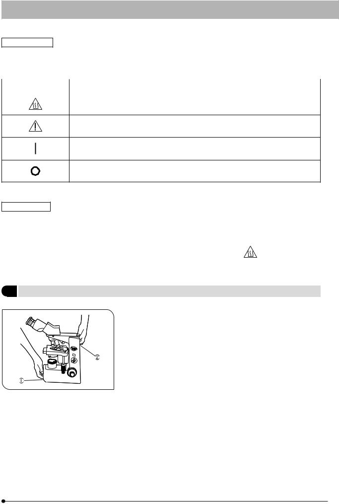
5.When moving the microscope, carefully carry it with one hand under the base @ and the other hand holding at the recessed handle on the
rear of the arm ² as shown in the illustration on the left.
#Damage to the microscope will occur if you hold it by the stage, X- axis/Y-axis knob, binocular section of the observation tube, etc. Also make sure that eyepieces, specimen, filters, etc. do not fall off.
#Sliding the microscope on the surface of the table may damage or tear off the rubber feet and/or scratch the table top surface.
2

2Maintenance and Storage
1.Clean all glass components by wiping gently with gauze. To remove fingerprints or oil smudges, wipe with gauze slightly moistened with a mixture of ether (70%) and alcohol (30%).
 Since solvents such as ether and alcohol are highly flammable, they must be handled carefully. Be sure to keep these chemicals away from open flames or potential sources of electrical sparks -- for example, electrical equipment that is being switched on or off. Also remember to always use these chemicals only in a well-ventilated room.
2.Do not attempt to use organic solvents to clean the non-optical components of the microscope. To clean them, use a lint-free, soft cloth lightly moistened with a diluted neutral detergent.
3.Do not disassemble any part of the microscope as malfunction or damage may occur.
4.When not using the microscope, ensure that the frame is cooled down and store it in a locker or cover it with a dust cover.
5.When disposing of the microscope, check the regulations and rules of your local goverment and be sure to observe them.
3Caution
If the microscope is used in a manner not specified by this manual, the safety of the user may be imperiled. In addition, the equipment may also be damaged. Always use the equipment as outlined in this instruction manual.
The following symbols are used to set off text in this instruction manual.
 : Indicates that failure to follow the instructions in the warning could result in bodily harm to the user and/or damage to equipment (including objects in the vicinity of the equipment).
# : Indicates that failure to follow the instructions could result in damage to equipment. } : Indicates commentary (for ease of operation and maintenance).
This device complies with the requirements of directive 98/79/EC concerning in vitro diagnostic medical devices. CE marking means the conformity to the directive.
NOTE : This equipment has been tested and found to comply with the limits for a Class A digital device, pursuant to Part 15 of the FCC Rules. These limits are designed to provide reasonable protection against harmful interference when the equipment is operated in a commercial environment. This equipment generates, uses, and can radiate radio frequency energy and, if not installed and used in accordance with the instruction manual, may cause harmful interference to radio communications. Operation of this equipment in a residential area is likely to cause harmful interference in which case the user will be required to correct the interference at his own expense.
FCC WARNING : Changes or modifications not expressly approved by the party responsible for compliance could void the user's authority to operate the equipment.
3

CX41
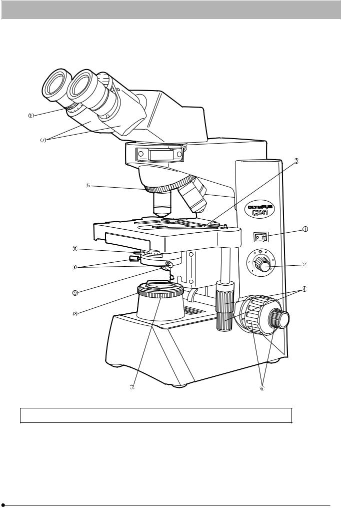
NOMENCLATURE
}The following illustration shows the CX41RF which is the microscope frame with the X-axis/Y-axis knobs provided on the right side. The CX41LF is X-axis/Y-axis knobs are provided on the left side.
* The stage is shipped with the two transport pins locked. When using the microscope for the first time, remove the transport lock pins before use.
}If you have not yet assembled the microscope, read Chapter 7, “ASSEMBLY” on pages 21 to 24.
Eyepieces
Diopter adjustment ring (Page 11)
Revolving Nosepiese
Objective
Specimen holder (Page 9)
Transport lock pin*
Aperture iris diaphragm knob (Page 13)
Condenser centering screws (Page 12)
Condenser
Filter holder
Place a 45 mm filter and the U-POT polarizer on this.
Field iris diaphragm ring (Page 7)
Interpupillar distance scale (Page 10)
Observation Tube
Dummy slider (Page 7)
Microscope Frame
Transport lock pin*
Main switch (Page 7)
Light intensity control knob (Page 7)
Stage
Fine focus adjustment knob (Page 8)
Coarse focus adjustment knob (Page 8)
X-axis knob (Page 10)
Y-axis knob (Page 10)
4
SUMMARY OF BRIGHTFIELD OBSERVATION
PROCEDURE
|
|
|
|
|
|
|
|
|
|
|
|
|
|
|
|
|
|
|
|
|
|
|
|
|
|
|
|
|
|
|
|
(Controls Used) (Page) |
|
|
|
|
|
|
|
|
|
|
|
|
|
|
|
|
|
|
|
|
|
|
|||||||||||||
Set the main switch to “ |
|
” (ON) and adjust |
|
|
|
|
|
|
|
|
|
|
|
|
|
|
|
|
|
|
|
|
|
|
|
|
|
|
|
@Main switch |
(P. 7) |
||
|
|
|
|
|
|
|
|
|
|
|
|
|
|
|
|
|
|
|
|
|
|
|
|
|
|
|
|
||||||
|
|
|
|
|
|
|
|
|
|
|
|
|
|
|
|
|
|
|
|
|
|
|
|
|
|
|
|
||||||
the brightness. |
|
|
|
|
|
|
|
|
|
|
|
|
|
|
|
|
|
|
|
|
|
|
|
|
|
|
|
²Light intensity knob |
(P. 7) |
||||
|
|
|
|
|
|
|
|
|
|
|
|
|
|
|
|
|
|
|
|
|
|
|
|
|
|
|
|
|
|
|
|
³Specimen holder |
(P. 9) |
|
|
|
|
|
|
|
|
|
|
|
|
|
|
|
|
|
|
|
|
|
|
|
|
|
|
|
|
|
|
|
|
||
|
|
|
|
|
|
|
|
|
|
|
|
|
|
|
|
|
|
|
|
|
|
|
|
|
|
|
|
|
|
|
|
||
Place the specimen on the stage. |
|
|
|
|
|
|
|
|
|
|
|
|
|
|
|
|
|
|
|
||||||||||||||
|
|
|
|
|
|
|
|
|
|
|
|
|
|
|
|
|
|
|
|
|
|
|
|
|
|
|
|X-axis/.Y-axis knobs |
(P.10) |
|||||
|
|
|
|
|
|
|
|
|
|
|
|
|
|
|
|
|
|
|
|
|
|
|
|
|
|
|
|
|
|
|
|
||
|
|
|
|
|
|
|
|
|
|
|
|
|
|
|
|
|
|
|
|
|
|||||||||||||
|
|
|
|
|
|
|
|
|
|
|
|
|
|
|
|
|
|
|
|
|
|
|
|
|
|
|
|
|
|
|
|
|
|
Engage the 10X objective in the light path. |
|
|
|
|
|
|
|
|
|
|
|
|
|
|
|
ƒRevolving nosepiece |
|
||||||||||||||||
|
|
|
|
|
|
|
|
|
|
|
|
|
|
|
|
|
|
|
|
|
|
|
|
|
|
|
|
||||||
|
|
|
|
|
|
|
|
|
|
|
|
|
|
|
|
|
|
|
|
|
|
||||||||||||
|
|
|
|
|
|
|
|
|
|
|
|
|
|
|
|
|
|
|
|
|
|||||||||||||
|
|
|
|
|
|
|
|
|
|
|
|
|
|
|
|
|
|
|
|
|
|
|
|
|
|
|
|
|
|
|
|
|
|
Bring the specimen in focus. |
|
|
|
|
|
|
|
|
|
|
|
|
|
|
|
|
|
|
|
|
|
|
|
|
|
|
|
…Coarse/fine focus adjustment knobs |
(P. 8) |
||||
|
|
|
|
|
|
|
|
|
|
|
|
|
|
|
|
|
|
|
|
|
|
|
|
|
|
|
|||||||
|
|
|
|
|
|
|
|
|
|
|
|
|
|
|
|
|
|
|
|
|
|
|
|
|
|
|
|
|
|
|
|
†Binocular tube |
(P 10) |
|
|
|
|
|
|
|
|
|
|
|
|
|
|
|
|
|
|
|
|
|
|
|
|
|
|
|
|
|
|
|
|
||
|
|
|
|
Adjust the interpupillary distance. |
|
|
|
|
|
|
|
|
|||||||||||||||||||||
|
|
|
|
|
|
|
|
|
|
|
|
‡Diopter adjustment ring |
(P. 11) |
||||||||||||||||||||
|
|
|
|
Adjust the diopter. |
|
|
|
|
|
|
|
|
|||||||||||||||||||||
|
|
|
|
|
|
|
|
|
|
|
|
ŠCondenser height adjustment knob |
(P. 12) |
||||||||||||||||||||
|
|
|
|
Adjust the light axis. |
|
|
|
|
|
|
|
|
|||||||||||||||||||||
|
|
|
|
|
|
|
|
|
|
|
|
‰Auxiliary lens centering knob |
(P. 12) |
||||||||||||||||||||
|
|
|
|
|
|
|
|
|
|
|
|
|
|
|
|
|
|
|
|
|
|
|
|
|
|
|
|
|
|
|
|
||
|
|
|
|
|
|
|
|
|
|
|
|
|
|
|
|
|
|
|
|
|
|
|
|
|
|
|
|
|
|
|
|
||
|
|
|
|
|
|
|
|
|
|
|
|
|
|
|
|
|
|
|
|
|
|
|
|
|
|
|
|
|
|
|
|
|
|
Adjust the aperture iris and field iris |
|
|
|
|
|
|
|
|
|
|
|
|
|
|
|
|
|
|
|
|
|
|
|
|
|
|
|
‹Aperture iris diaphragm knob |
(P. 13) |
||||
diaphragms. |
|
|
|
|
|
|
|
|
|
|
|
|
|
|
|
|
|
|
|
|
|
|
|
|
|
|
|
ŒField iris diaphragm ring |
(P. 7) |
||||
|
|
|
|
|
|
|
|
|
|
|
|
|
|
|
|
|
|
|
|
|
|
|
|
|
|
|
|
|
|
|
|
ƒRevolving nosepiece |
|
|
|
|
|
|
|
|
|
|
|
|
|
|
|
|
|
|
|
|
|
|
|
|
|
|
|
|
|
|
|
|
|
|
|
|
|
|
|
|
|
|
|
|
|
|
|
|
|
|
|
|
|
|
|
|
|
|
|
|
|
|
|
|
|
|
|
|
|
Engage the desired objective in the light path |
|
|
|
|
|
|
|
|
|
|
|
|
|
|
|
|
|
|
|
|
|
|
|
|
|
|
|
|
|||||
|
|
|
|
|
|
|
|
|
|
|
|
|
|
|
|
|
|
|
|
|
|
|
|
|
|
|
…Coarse/fine focus adjustment knobs |
(P. 8) |
|||||
and bring the specimen in focus. |
|
|
|
|
|
|
|
|
|
|
|
|
|
|
|
|
|
|
|
|
|
|
|
|
|
|
|
||||||
|
|
|
|
|
|
|
|
|
|
|
|
|
|
|
|
|
|||||||||||||||||
|
|
|
|
|
|
|
|
|
|
|
|
|
|
|
|
|
|
|
|
™ Filters |
(P. 13) |
||||||||||||
|
|
|
|
|
|
|
|
|
|
|
|
|
|
|
|
|
|
|
|||||||||||||||
|
|
|
|
Insert the required filters. |
|
|
|
|
|
|
|
|
|
|
|
|
|
|
|||||||||||||||
|
|
|
|
|
|
|
|
|
|
|
|
|
|
|
|
|
|
|
|
|
|||||||||||||
|
|
|
|
|
|
|
|
|
|
|
|
|
|
|
|
|
|
|
²Light intensity knob |
(P. 7) |
|||||||||||||
|
|
|
|
|
|
|
|
|
|
|
|
|
|||||||||||||||||||||
|
|
|
|
Adjust the brightness. |
|
|
|
|
|
|
|
|
|
|
|
|
|
|
|||||||||||||||
|
|
|
|
|
|
|
|
|
|
|
|
|
|
|
|
|
|
|
|
|
|||||||||||||
|
|
|
|
|
|
|
|
|
|
|
|
|
|
|
|
||||||||||||||||||
|
|
|
|
|
|
|
|
|
|
|
|
||||||||||||||||||||||
Start observation. |
|
|
|
|
|
|
|
|
|
|
|||||||||||||||||||||||
5
CX41
} Copy the observation procedure pages on a separate sheet and post it near your microscope.
6
USING THE CONTROLS
3-1 Base
1 |
|
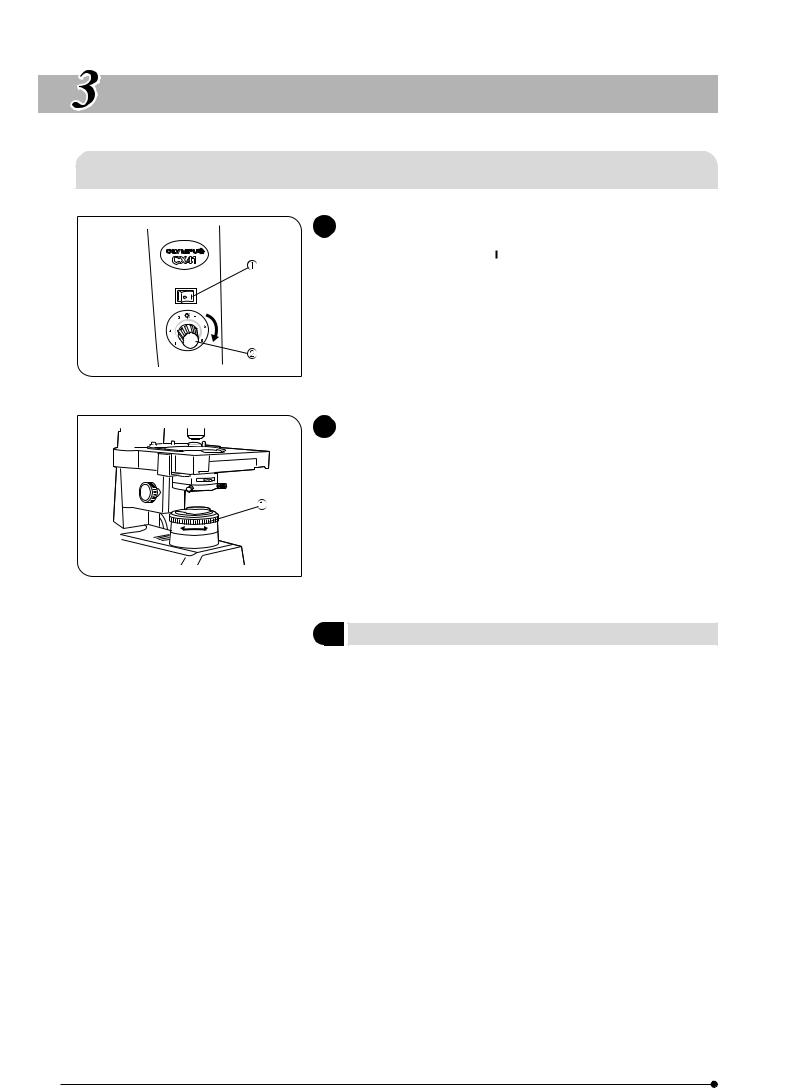
Turning On the Bulb |
(Fig. 3) |
|
|
|
|
1. Set the main switch @ to “ ” (ON).
2. Turn the light intensity knob ² clockwise in the direction of the arrow to make the illumination brighter or counterclockwise to make it darker.
The numbers around the knob indicates the reference voltage values.
Fig. 3
2 |
|
Field Iris Diaphragm |
(Fig. 4) |
|
|
|
|
Using the field iris diaphragm ring @, adjust the diameter of the field iris for objective power to the extent that it just circumscribes the field of view. When the field iris diaphragm is stopped down to circumscribe the field of view, it will exclude extraneous light and improve image contrast within the field of view.
#When using the 100X objective, the field iris diaphragm image will not be visible within the field of view. Accordingly, stop down the diaphragm to its smallest diameter.
Fig. 4
3Dummy Slider
The dummy slider provided with the microscope frame can be used to accommodate the optional transmitted light analyzer (U-ANT).
By preparing a transmitted light polarizer (U-POT) and polarizing light condenser (CH3-CDP), simple polarized light observation becomes possible.
Also refer to the instruction manual of the CX-POL.
7
CX41
3-2 Focusing Block
1 |
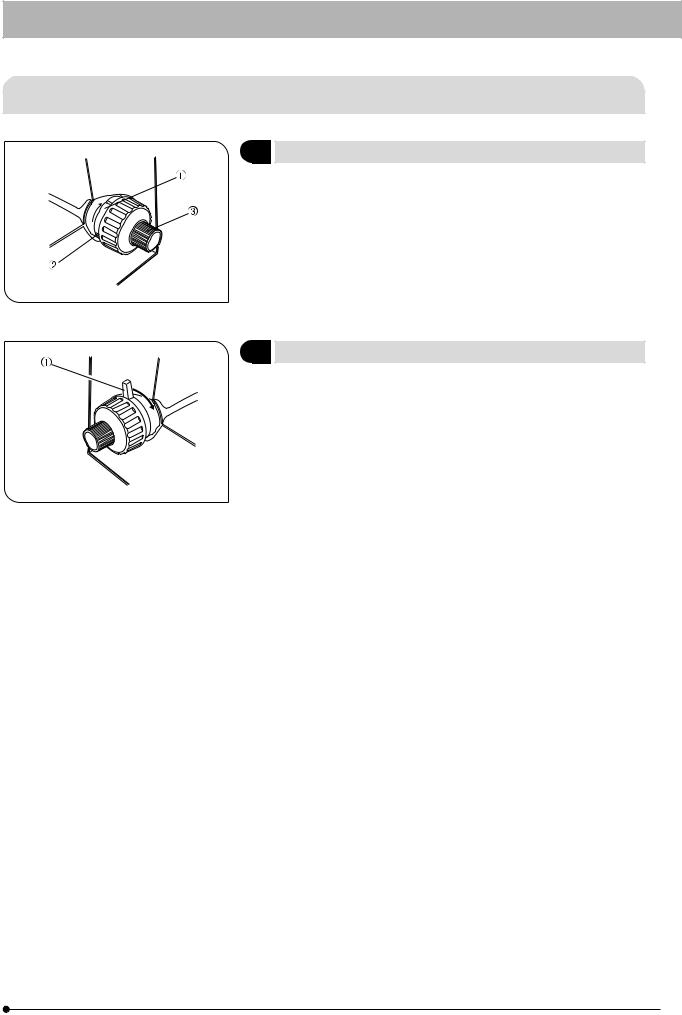
Adjusting the Coarse Adjustment Knob Tension (Fig. 5) |
|
1. The coarse adjustment knob tension is preadjusted for easy use. |
|
However, if desired, one can change the tension using the tension |
|
adjustment ring @. Applying a large flat-bladed screwdriver to any of |
|
the grooves ² on the circumference of the ring, turning the ring |
|
clockwise (in the direction of the arrow) increases tension, and vice |
|
versa. |
|
2. The tension is too low if the stage drops by itself of focus is quickly lost |
|
after adjustment with the fine adjustment knob ³. In this case, turn the |
Fig. 5 |
ring in the direction of the arrow to increase tension. |
|
2 |
Pre-focusing Lever |
(Fig. 6) |
|
|
The pre-focusing lever ensures that the objective does not come in |
||
|
contact with the specimen and simplifies focusing. |
|
|
|
After focusing on the specimen with the coarse adjustment knob, turn |
||
|
this lever @ clockwise (in the direction of the arrow) and lock; the |
||
|
upper limit on coarse adjustment movement is set at the locked |
||
|
position. |
|
|
|
}Focusing using the fine adjustment knob is not affected by the pre- |
||
|
focusing dial. Accordingly, after using the coarse adjustment knob to |
||
Fig. 6 |
lower the stage for changing specimens or applying immersion oil |
||
(see section 3-6), refocusing is easily accomplished by rotating the |
|||
|
|||
|
coarse adjustment to reach the pre-focusing position, then making fine |
||
|
adjustments with the fine adjustment knob. |
|
|
|
#When not required, leave the pre-focusing dial unlocked. |
|
|
8
 Loading...