


CX21

INSTRUCTIONS
CX21
EDUCATION MICROSCOPE
A X 7 4 0 3
This instruction manual is for the Olympus Education Microscopes Model CX21. To ensure the
safety, obtain optimum performance and to familiarize yourself fully with the use of this microscope,
we recommend that you study this manual thoroughly before operating the microscope. Retain this
instruction manual in an easily accessible place near the work desk for future reference.
IVD


CX21
CONTENTS
4
5
6
7-11
IMPORTANT — Be sure to read this section for safe use of the equipment. —
1 STANDARD COMPONENT UNITS
2 NOMENCLATURE
3
4 DETAILED OBSERVATION PROCEDURE
SUMMARY OF BRIGHTFIELD OBSERVATION PROCEDURE
1-3
10-1 System Diagram of Optional Accessories .............................................................................. 19
10-2 Installation and Operation of Optional Accessories....................................... 19-21
1 Turning the Lamp ON ........................................... 7
3 Adjusting the Focus ................................................
8
5 Adjusting the Diopter ............................................ 9
2
Placing Specimen on the Stage
.................... 7
4
Adjusting the Interpupillary Distance
.....................
9
5 ONE-POINT ADVICE
6 TROUBLESHOOTING GUIDE
7 SPECIFICATIONS
8 OPTICAL CHARACTERISTICS
9 ASSEMBLY
10 OPTIONAL ACCESSORIES
12
13-14
15
16
17- 18
19-21
1 Cord Hanger CH3-CH ............................................................................................................................................................................................ 19
2 Filter Holder CH2-FH ...............................................................................................................................................................................................
20
3 Darkfield Ring CH2-DS ........................................................................................................................................................................................ 20
4 Reflection Mirror CH20-MM ..........................................................................................................................................................................
20
5 Eyepieces WHC15X/WHC15X-H
.......................................................................................................................................................................................................
21
6 Using the eyepiece micrometer
........................................................................................................................................................................................................
21
6 Adjusting the Condenser Position and Aperture Iris Diaphragm ............................................................. 10
7 Switching the Objectives ............................
10
8
Using the 100X Immersion Objective .....................
11
PROPER SELECTION OF THE POWER SUPPLY CORD ....................................................... 22-23
1
IMPORTANT
SAFETY PRECAUTIONS
1. After the equipment has been used in an observation of a specimen
that is accompanied with a potential of infection, clean the parts
coming in contact with the specimen to prevent infection.
· Moving this product is accompanied with the risk of dropping the
specimen. Be sure to remove the specimen before moving this product.
· In case the specimen is damaged by erroneous operation, promptly
take the infection prevention measures.
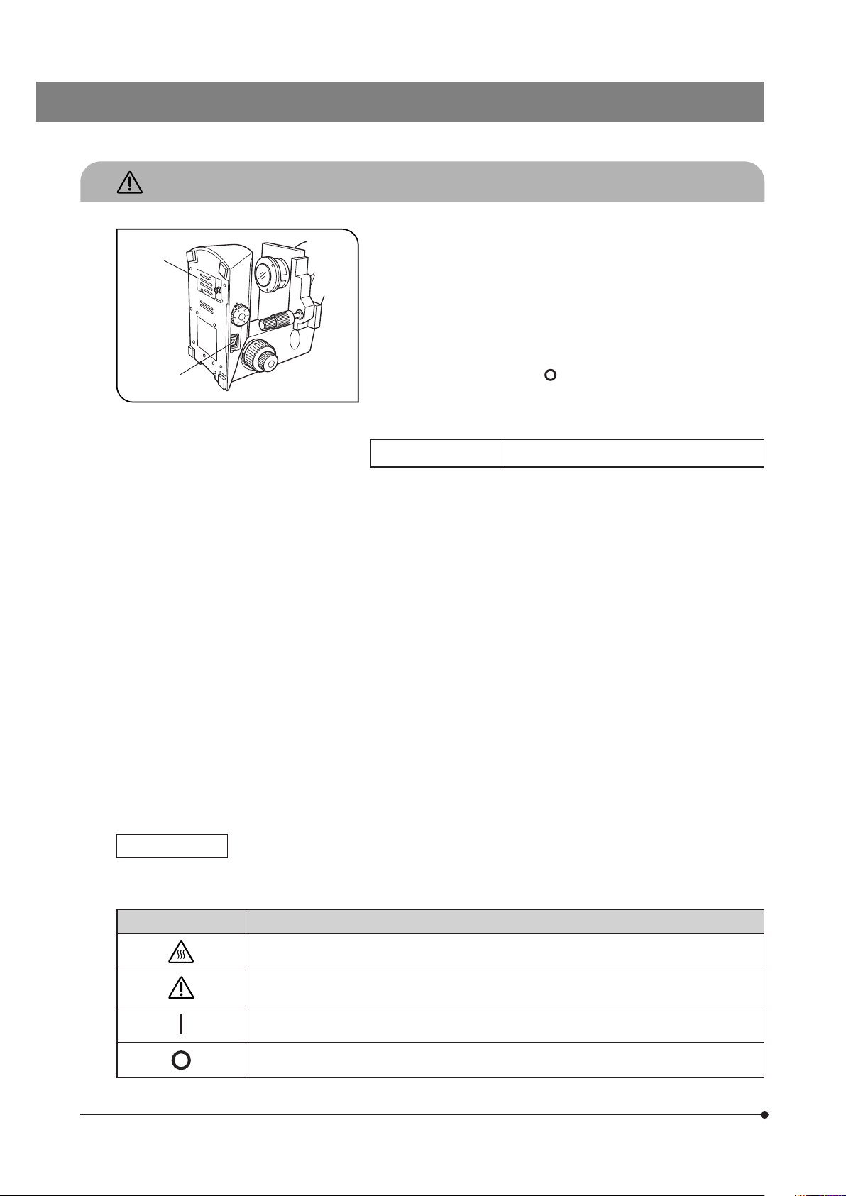
2. To avoid potential shock hazards and burns when replacing the lamp
bulb, set the main switch 1 to “ ” (OFF) then disconnect the power cord
from the wall outlet in advance. Whenever you replace the bulb during
use or right after use, allow the lamp socket 2 and bulb to cool before
touching. (Fig. 1)
Applicable lamp bulb: 6V20WHAL halogen bulb (Philips Type 7388)
3. Install the microscope on a sturdy, level table or bench so as not to block
the air vents on the underside of the base.
Do not place the microscope on a flexible surface, as this could result in
blocking the air vents and cause overheating or a fire.
4. Always use the power cord provided by Olympus. If no power cord is
provided, please select the proper power cord by referring to the section
“PROPER SELECTION OF THE POWER SUPPLY CORD” at the end of
this instruction manual. If the proper power cord is not used, product
safety performance cannot be warranted.
5. When installing the microscope, route the power cord away from the
microscope frame. Should the power cord come in contact with a hot
part, the power cord could melt and cause electric shock.
6. Always ensure that the grounding terminal of the microscope and that
of the wall outlet are properly connected. If the equipment is not grounded,
Olympus can no longer warrant the electrical safety performance of the
equipment.
7. Never allow metallic objects penetrate into the air vents of the microscope frame as this could result in electrical shock, personal injury and
equipment damage.
8. After operation or in case of abnormality, be sure to disconnect the power
cord from the connector on the microscope or from the wall power outlet.
Fig. 1
Safety Symbols
The following symbols are found on the microscope. Study the meaning of the symbols and always use the equipment
in the safest possible manner.
Symbol Explanation
Indicates that the surface becomes hot, and should not be touched with bare hands.
Indicates that the main switch is ON.
Indicates that the main switch is OFF.
Before use, carefully read the instruction manual. Improper use could result in personal injury to
the user and/or damage to the equipment.
@
²
2
CX21
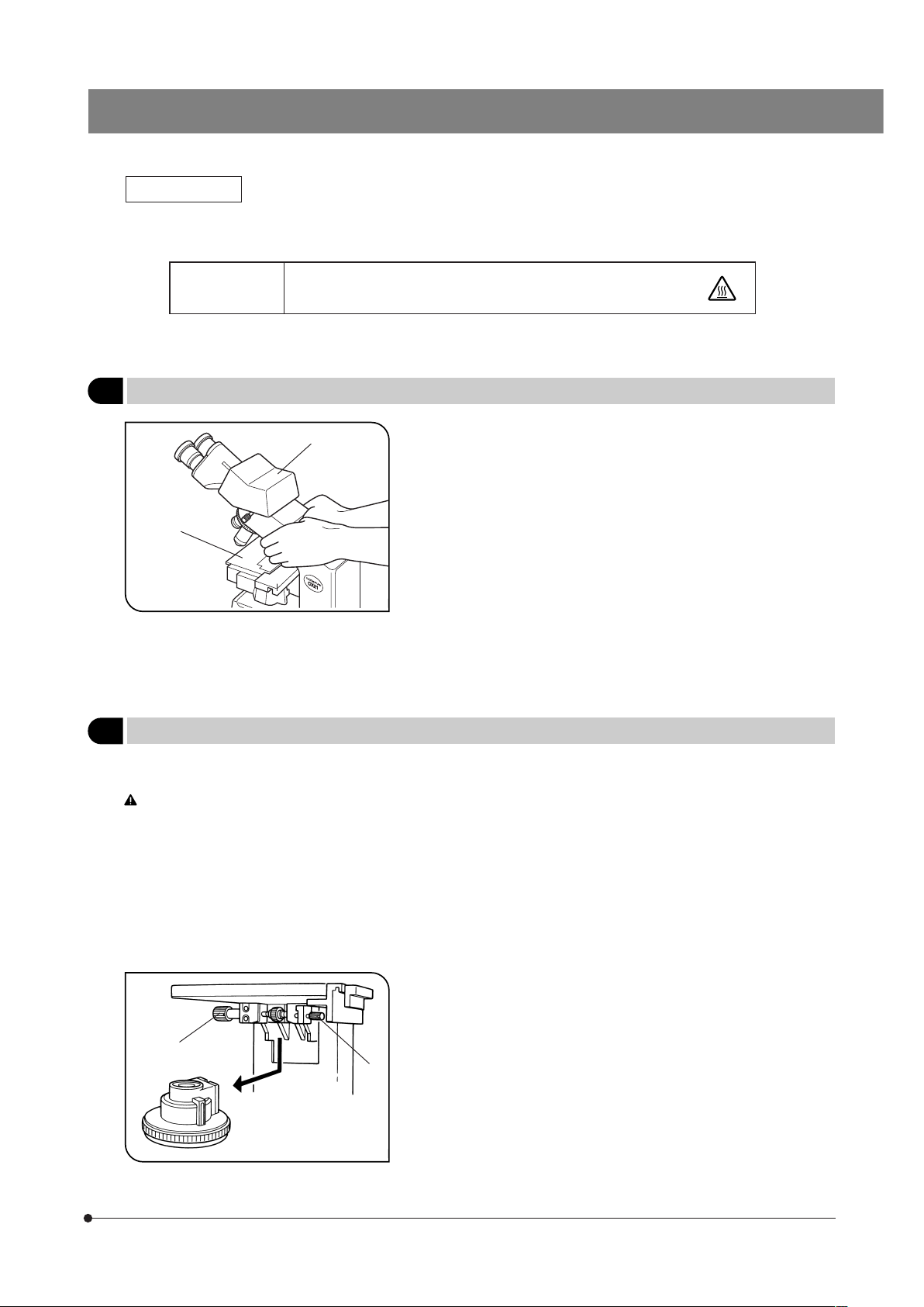
Warning Label
A warning indication label is attached to every part where special precaution is required when handling and using the
microscope. Always heed the warnings.
Warning label
position
Bottom of microscope
frame
[Warning against high temperature in
lamp bulb replacement]
If the warning label is stained or peeled off, contact Olympus.
1
Getting Ready
1. A microscope is a precision instrument. Handle it with care and avoid
subjecting it to sudden or severe impact.
2. Do not use the microscope where it is subjected to direct sunlight,
high temperature and humidity, dust or vibrations. (For the operating
conditions, see chapter 7, “SPECIFICATIONS” on Page 15.)
3. Always use the tension adjustment ring to adjust the rotation tension of
the coarse adjustment knob.
4. The microscope is ventilated by natural convection. Be sure to leave
enough spaces (10 cm or more) around it when installing it.
5. When carrying the microscope, hold both sides around the hole of the
arm as shown in Fig. 2 and carry carefully.
#To prevent damage, do not hold the microscope by the stage 1 or
observation tube 2.
Be sure to remove the specimen; otherwise, it may fall.
Fig. 2
2
Maintenance and Storage
1. Clean all glass components by wiping gently with gauze. To remove fingerprints or oil smudges, wipe with gauze slightly
moistened with a mixture of ether (70%) and alcohol (30%).
Since solvents such as ether and alcohol are highly flammable, they must be handled carefully. Be sure to keep
these chemicals away from open flames or potential sources of electrical sparks —— for example, electrical equipment that is being switched on or off. Also remember to always use these chemicals only in a well-ventilated
room.
2. Do not attempt to use organic solvents to clean the microscope components other than the glass components. To clean
them, use a lint-free, soft cloth slightly moistened with a diluted neutral detergent.
3. Do not disassemble any part of the microscope as this could result in malfunction or reduced performance.
4. When not using the microscope, ensure that the frame is cooled down and store it in a dry locker or cover it with a dust
cover.
Fig. 3
5. To clean the condenser, fully loosen the securing knob 1, then remove
the condenser by lowering it with the condenser height adjustment knob
2, and wipe the front lens of the condenser.
The condenser can be attached by reversing the above removal
procedure.
6. When disposing of the microscope. Check the regulations and rules
of your local government and be sure to observe them.
@
²
@
²

3
3
Caution
If the microscope is used in a manner not specified by this manual, the safety of the user may be imperiled. In addition,
the equipment may also be damaged. Always use the equipment as outlined in this instruction manual.
The following symbols are used to set off text in this instruction manual.
: Indicates that failure to follow the instructions in the warning could result in bodily harm to the
user and/or damage to equipment (including objects in the vicinity of the equipment).
# : Indicates that failure to follow the instructions could result in damage to equipment.
} : Indicates commentary (for ease of operation and maintenance).
NOTE: This equipment has been tested and found to comply with the limits for a Class A digital device,
pursuant to Part 15 of the FCC Rules. These limits are designed to provide reasonable protection
against harmful interference when the equipment is operated in a commercial environment. This
equipment generates, uses, and can radiate radio frequency energy and, if not installed and used in
accordance with the instruction manual, may cause harmful interference to radio communications.
Operation of this equipment in a residential area is likely to cause harmful interference in which case
the user will be required to correct the interference at his own expense.
FCC WARNING: Changes or modifications not expressly approved by the party responsible for compliance
could void the user’s authority to operate the equipment.
This device complies with the requirements of directive 98/79/EC concerning in vitro diagnostic
medical devices. CE marking means the conformity to the directive.
4
CX21
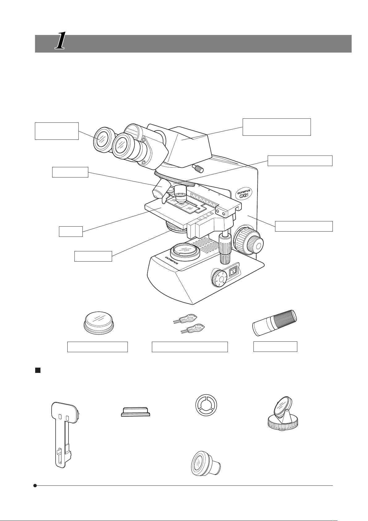
STANDARD COMPONENT UNITS
}After opening the package, make sure that the correct component units for the selected set are present.
· The differences between the CX21FS1 and CX21FS2 lie in the number of objectives and presence of immersion oil.
# The objectives have been screwed in tightly to prevent them from being loosened during transportation. To
remove an objective, turn it counterclockwise while holding it with a rubber sheet, etc., so that your fingers don’t slip.
Eyepieces
(Fixed at 10X)
Stage
Condenser
Binocular observation
tube
Revolving nosepiece
Microscope frame
Objectives
· 4X, 10X, 40X, 100X
(CX21FS1)
· 4X, 10X, 40X
(CX21FS2)
6V20WHAL halogen bulb
Immersion oil
· Provided with a set including
the 100X objective.
Daylight (blue) filter
Optional Accessories
· Cord Hanger
CH3-CH
· Filter Holder
CH2-FH
· Reflection Mirror
CH20-MM
· Eyepieces
WHC15X
WHC15X-H
· Darkfield Ring
CH2-DS
5
“ ”: Power ON
“ ”: Power OFF
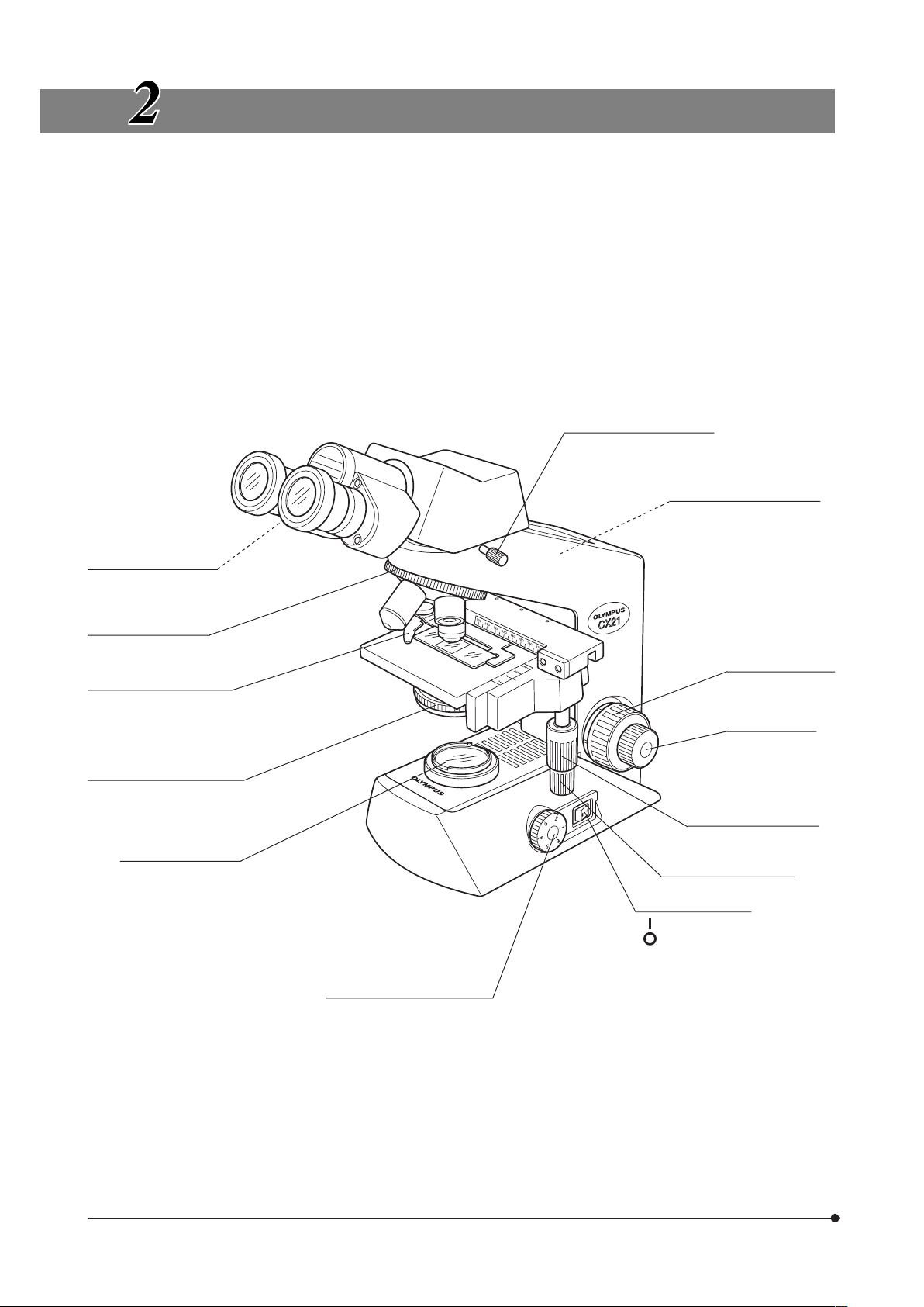
NOMENCLATURE
}The following items have been attached at the factory to prevent deterioration during transport. Remove these items and
retain them for future use. Then loosen the observation tube clamping knob and correct the orientation of the eyepieces
as shown in the illustration below.
1 Revolving nosepiece/observation tube transport band
2 Stage and specimen holder protection sheet
3 Protective pad below the stage
}Attach the lamp bulb and power cord as described in chapter 9, “ASSEMBLY” on pages 17-18.
Diopter adjustment ring
(Page 9)
}For detailed description of each control, refer to the page indicated inside parentheses.
Specimen holder (Page 7)
Aperture iris diaphragm ring
(Page 10)
Filter holder (Page 20)
Light intensity adjustment
knob (Page 7)
Revolving nosepiece
(Page 10)
Observation tube clamping
knob
Pre-focusing knob (Page 9)
Specimen holder Y-axis
feed knob (Page 7)
Specimen holder X-axis
feed knob (Page 7)
Fine adjustment
knob (Page 8)
Coarse adjustment
knob (Page 8)
Main switch (Page 7)
6
CX21
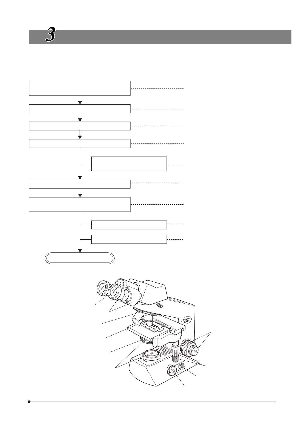
SUMMARY OF BRIGHTFIELD OBSERVATION PROCEDURE
Set the main switch to “ I " (ON) and adjust
the brightness.
1Main switch (P. 7)
2Light intensity adjustment knob (P. 7)
Place the specimen on the stage.
3Specimen holder (P. 7)
4X-axis/Y-axis feed knobs (P. 7)
Engage the 10X objective in the light path. 5Revolving nosepiece (P. 10)
Bring the specimen in focus
6Coarse/fine focus adjustment knobs (P. 8)
Adjust the interpupillary distance.
Adjust the diopter.
7Binocular tube (P. 9)
8Diopter adjustment ring (P. 9)
Adjust the aperture iris diaphragm. 9Aperture iris diaphragm ring (P. 10)
Engage the objective to be used in the light
path and bring the specimen in focus.
aFilters (Diameter: 32.5 mm or 45 mm) (P. 20)
Engage the required filters.
5Revolving nosepiece (P. 10)
6Coarse/fine adjustment knobs (P. 8)
Adjust the brightness.
2Light intensity adjustment knob (P. 7)
Start observation.
(Controls Used)
(Page)
1
2
4
6
a
9
3
5
7
8
 Loading...