


 Loading...
MAINTENANCE / ON-SITE - MANUAL
Electro Surgical Generator
ESG-400
7.022.211 / ISSUE 5

ESG-400
INTRODUCTION
Introduction
The intended use depends on the approval of the country. Refer to the instructions for use of the electrosurgical unit.
Maintenance instructions
This maintenance manual contains essential information on using and maintaining this electrosurgical generator safely and effectively. Instructions for the operation of this electrosurgical generator and related danger, warnings and cautions concerning electrosurgery are beyond the scope of this maintenance manual. Before using and maintaining, thoroughly review this manual and the instructions for use or maintenance manuals of all equipment which will be used during maintenance. Use the equipment as instructed. Keep this manual in a safe, accessible location. If you have any questions or comments about any information in this maintenance manual, contact Olympus.
Signal words
The following signal words are used throughout this maintenance manual:
|
DANGER |
Indicates an imminently hazardous situation which, if not avoided, will result in |
|
d |
|
|
death or serious injury. |
|
|
|
Indicates a potentially hazardous situation which, if not avoided, could result in |
|
WARNING |
||
|
|
|
death or serious injury. |
|
|
|
Indicates a potentially hazardous situation which, if not avoided, may result in |
|
CAUTION |
||
|
|
|
minor or moderate injury. It may also be used to alert against unsafe practices |
|
|
|
or potential equipment damage. |
|
|
|
|
|
NOTE |
|
Indicates additional helpful information. |
|
|
|
|
User qualifications
The user must have received appropriate training in using this electrosurgical generator. The following instructions are for use by qualified personnel only. Use of this maintenance manual by other individuals is prohibited. The training will be provided by authorized representatives of Olympus during installation and commissioning.
NOTE The user must have received appropriate training in using, servicing, adjustment, updating and upgrading this electrosurgical generator.
Federal Law of the USA restricts this device to use by, or on the order of, a physician.
7.022.211 / ISSUE 5 |
2 / 110 |
Introduction |

ESG-400
Precautions
High frequency leakage current or spark discharge may cause user burns.
Follow the dangers, warnings and cautions given below when handling and servicing this electrosurgical unit. This information is to be supplemented by the dangers, warnings and cautions given in each chapter.
User-related error prevention
WARNING Improper use
The safety and effectiveness of electrosurgical interventions depend not only on the design of the equipment used, but also to a major extent on factors which are under the control of the user. It is therefore extremely important to read, understand and follow the instructions supplied with the electrosurgical generator and the accessories in order to ensure safety and effectiveness.
Always use the electrosurgical generator as outlined in this maintenance manual. Improper use will not only impede functions and prevent optimum performance, but may cause equipment damage and / or complications. Before each use, always inspect the equipment as outlined in this maintenance manual.
WARNING Annual safety checks / Inspection
The electrosurgical generator and the footswitch must undergo a safety check in yearly intervals in accordance with the national statutory regulations (refer to chapter 7 “Inspection”).
Environmental conditions
CAUTION  Interference of the unit with other equipment
Be sure that this electrosurgical unit is not used adjacent to or stacked with other equipment (other than the components of this electrosurgical unit or system) to avoid electromagnetic interference.
Before use, thoroughly confirm the compatibility of all equipment.
To ensure electrical safety, the electrosurgical unit should not be used in conjunction with:
•Electrical equipment whose safety against leakage current is not guaranteed.
•Electrosurgical equipment whose safety in combined use is not guaranteed.
The electrosurgical generator complies with the electromagnetic compatibility (EMC) standard. Nevertheless, when the electrosurgical generator is active it may disturb neighboring electronic equipment. If an auxiliary computer system is in use together with the electrosurgical generator and endoscopic imaging techniques, the image on the monitor might freeze or blackout. Follow the instructions in “Electromagnetic Compatibility (EMC) information” in the Appendix of the instruction for use regarding electromagnetic ambient conditions.
Never loop the cords (active cord, bipolar cord, neutral electrode cord) or bundle cords together with cords belonging to other medical equipment. The high frequency signals or spark discharge noise generated by the unit may interfere with the operation of other medical equipment.
Do not use the electrosurgical unit in a location exposed to strong electromagnetic radiation (microwave or short-wave medical treatment equipment, Magnetic Resonance Imaging, radio or mobile phone equipment). Electrosurgical unit malfunction can occur.
CAUTION Unsuitable temperature and humidity
The electrosurgical generator should only be used under the conditions as described in chapter 1-3 (Limitations). Use under other conditions may impede normal performance and / or result in equipment damage.
7.022.211 / ISSUE 5 |
3 / 110 |
Introduction |

ESG-400
Accessories
WARNING  Mechanical stress
Do not apply excessive bending, straining, or squeezing force to any cords. It may cause malfunction.
CAUTION Non-compatible accessories and accessory damage
The electrosurgical generator shall only be used with compatible accessories. When connecting accessories (cords, electrodes, HF instruments) avoid output settings where the maximum output voltage of the electrosurgical generator may exceed the rated accessory voltage (refer to “Mode characteristics”, “Output characteristics” in the Appendix of the instruction for use, and the instruction manual of the accessory). For a list of compatible neutral electrodes, refer to “Specifications” in the Appendix of the instruction for use.
Before use, the electrosurgical unit and accessories must be examined for damage. All communication cables and its plugs must be free of scratches and cracks. Cables and accessories with damaged insulation or connections must not be used.
Electric shock
WARNING Grounding failure
To prevent the risk of electric shock, the housing of the electrosurgical unit must be grounded. Always connect the power cord plug to a properly grounded wall outlet. Do not use a 3-pin / 2-pin adapter, as it can impair safe operation of the unit.
WARNING User shock
To prevent user shock, malfunction and damage of the electrosurgical unit, keep liquids away from all electrical equipment.
When taking measurements or troubleshooting of the electrosurgical unit, take appropriate precautions, such as using isolated tools and equipment, using the “one hand rule,” etc.
CAUTION  Injury during servicing
When the housing is opened, there is a danger of electric shock. The unit must only be serviced by authorized technicians.
Burns
WARNING User
The maximum output voltage characteristics of the electrosurgical generator are shown in the diagrams in “Output characteristics” in the Appendix of the instruction for use. When setting the power level, first set it to a low level and increase it gradually. If the output is initially set to a high level, the electrode’s insulation may be damaged and cause user and / or patient burns. However, certain modes may present an unacceptable risk at low output power settings. For example, with the PulseCut fast mode or PulseCut slow mode, the risk of an excessive thermal effect rises if the output power setting is too low. Therefore, it is recommended that you perform basic testing before using the electrosurgical generator. If the instruction manual of the HF instrument to be used stipulate a rated voltage, the output should be set so that it does not exceed that voltage.
High frequency, high voltage signals that can cause severe burns are present in the monopolar / bipolar sockets described in this maintenance manual. Take appropriate precautions when testing and troubleshooting this area of the electrosurgical unit.
7.022.211 / ISSUE 5 |
4 / 110 |
Introduction |

ESG-400
Fire / Explosion
DANGER Ignitable anaesthetics / fire supporting gases
The risk of flammable gases or other materials being ignited exists with any contact of electrical energy. Precautionary measures must be taken to keep flammable materials and substances away from an active electrosurgical unit (do not use flammable anesthetics, nitrous oxide or oxygen). Otherwise, explosion or fire may result and cause serious injuries. This electrosurgical unit is not explosion-proof. Do not use the unit within an explosion zone.
WARNING  Ignitable cleaningand disinfection agents
Flammable agents used for cleaning and disinfection must be allowed to evaporate before the electrosurgical unit is used and serviced.
Non-flammable agents should be used for cleaning and disinfection wherever possible.
WARNING Risk of fire
Disconnect the power plug before changing the fuses! Replace fuses as marked. The fuses must only be replaced by authorized technicians.
Hazards and complications
WARNING  Contamination
The electrosurgical unit may be contaminated with infections materials; therefore, all surfaces of the unit’s housing should be cleaned before servicing according to chapter 1-8 (Cleaning).
WARNING |
Output performance |
|
|
|
|
|
|
Should any abnormal output be suspected during operation, immediately terminate the use of the equipment by releasing the footswitch. If the footswitch does not react, switch off the electrosurgical unit. Otherwise, malfunction of the equipment may cause an unintended increase in output.
WARNING |
Service persons |
|
|
|
|
Take additional precautions for service technicians, when using the unit’s service operation mode (see chapter 15, Service operation mode).
CAUTION Unit defect
To prevent electrosurgical unit damage, never short-circuit electrodes (accessories, neutral electrodes).
In the event of a defect or malfunction in the unit, an undesirably high output power may be emitted.
DANGER Unit defect
Never use the electrosurgical unit if an abnormality is suspected.
Repair and Maintenance
CAUTION Repair
Repairs must only be carried out by Olympus or a firm authorized by Olympus.
CAUTION  Maintenance
Preventive maintenance (inspection / periodic safety check) must only be carried out by a qualified person / technician.
7.022.211 / ISSUE 5 |
5 / 110 |
Introduction |

ESG-400
Copyright
©2011 Olympus Winter & Ibe GmbH. All rights reserved.
Unauthorized reproduction or distribution in part or in whole is prohibited.
Trademarks
OLYMPUS is a registered trademark of the Olympus Corporation.
The company names, product names, and proprietary technical terms in this document are the trademarks or registered trademarks of their respective owners.
7.022.211 / ISSUE 5 |
6 / 110 |
Introduction |

ESG-400
CONTENT
INTRODUCTION................................................................................................................ |
2 |
||
CONTENT.......................................................................................................................... |
|
7 |
|
CHAPTER 1: PRODUCT SPECIFICATIONS .................................................................... |
9 |
||
1 OUTLINE |
...................................................................................................................... |
10 |
|
1-1 |
Intended Use.................................................................................................................................... |
10 |
|
1-2 |
Compatibility..................................................................................................................................... |
10 |
|
1-3 |
Expected service life ........................................................................................................................ |
10 |
|
2 FEATURES ................................................................................................................... |
11 |
||
2-1 |
Application Modes............................................................................................................................ |
11 |
|
2-2 |
Accessories...................................................................................................................................... |
12 |
|
3 LIMITATIONS................................................................................................................ |
13 |
||
4 SPECIFICATIONS ........................................................................................................ |
14 |
||
4-1 |
ELECTROSURGICAL GENERATOR ESG-400 (REF: WB91051W) .............................................. |
14 |
|
4-2 |
Power cords (4.5 m angled plug)..................................................................................................... |
15 |
|
4-3 |
Footswitch (REF: WB50402W, double pedal) ................................................................................. |
16 |
|
4-4 |
Footswitch (REF: WB50403W, single pedal, optional) .................................................................... |
16 |
|
4-5 |
Neutral electrode cable “P-cord” (REF: MAJ-814, optional) ............................................................ |
16 |
|
4-6 |
Communication cable 0.25 m (REF: MAJ-1871, optional) .............................................................. |
17 |
|
4-7 |
Communication cable 10 m (REF: MAJ-1872, optional) ................................................................. |
17 |
|
4-8 |
Adapter for UHI-2/3 (REF: MAJ-1873, optional) .............................................................................. |
17 |
|
5 NAME AND FUNCTION OF EACH PART .................................................................... |
18 |
||
5-1 |
Symbols and descriptions ................................................................................................................ |
18 |
|
5-1-1 |
Safety related symbols ............................................................................................................ |
18 |
|
5-1-2 |
Front panel .............................................................................................................................. |
19 |
|
5-1-3 |
Touch screen ........................................................................................................................... |
19 |
|
5-1-4 |
Rear panel ............................................................................................................................... |
21 |
|
5-2 |
Front panel ....................................................................................................................................... |
22 |
|
5-3 |
Rear panel........................................................................................................................................ |
24 |
|
5-4 |
Bottom panel .................................................................................................................................... |
25 |
|
5-5 |
All screen ......................................................................................................................................... |
25 |
|
5-6 |
Set screen ........................................................................................................................................ |
26 |
|
5-7 |
Mode screen .................................................................................................................................... |
27 |
|
5-8 |
Footswitch with two pedals .............................................................................................................. |
28 |
|
5-9 |
Footswitch with one pedal (optional)................................................................................................ |
28 |
|
5-10 |
Neutral electrode cable “P-cord” (optional)...................................................................................... |
29 |
|
6 CONNECTOR ............................................................................................................... |
30 |
||
6-1 |
Docking Connector .......................................................................................................................... |
30 |
|
6-2 |
Monopolar Standard 1...................................................................................................................... |
30 |
|
6-3 |
Monoploar Standard 2 (Erbe)........................................................................................................... |
30 |
|
6-4 |
Bipolar Standard 3............................................................................................................................ |
30 |
|
6-5 |
Monopolar Neutral Electrode ........................................................................................................... |
31 |
|
6-6 |
Foot switch 1 (SIP/SOP) .................................................................................................................. |
31 |
|
6-7 |
Foot switch 2 (SIP/SOP) .................................................................................................................. |
32 |
|
7 SYSTEM DIAGRAM ..................................................................................................... |
33 |
||
8 CLEANING, STORAGE AND DISPOSAL .................................................................... |
34 |
||
8-1 |
Cleaning ........................................................................................................................................... |
34 |
|
8-2 |
Storage............................................................................................................................................. |
35 |
|
8-3 |
Disposal of the unit .......................................................................................................................... |
35 |
|
CHAPTER 2: BLOCK DESCRIPTION............................................................................. |
37 |
||
1 BLOCK DESCRIPTIONS.............................................................................................. |
38 |
||
1-1 |
Motherboard..................................................................................................................................... |
39 |
|
1-2 |
HVPS Board..................................................................................................................................... |
41 |
|
1-3 |
Generator board............................................................................................................................... |
41 |
|
1-4 |
Relay Board ..................................................................................................................................... |
41 |
|
1-5 |
Front Panel....................................................................................................................................... |
42 |
|
CHAPTER 3: REPAIR SYSTEM...................................................................................... |
43 |
||
7.022.211 / ISSUE 5 |
7 / 110 |
Content |

ESG-400
1 ESG-400 MAIN UNIT.................................................................................................... |
44 |
||
2 BOARD COMPATIBILITY............................................................................................. |
44 |
||
3 OPTIONAL ACCESSORIES......................................................................................... |
44 |
||
3-1 |
WB50402W (Footswitch with two pedals) ....................................................................................... |
44 |
|
3-2 |
WB50403W (Footswitch with one pedal)......................................................................................... |
44 |
|
3-3 |
MAJ-814 (Neutral electrode cable “P-cord”) .................................................................................... |
44 |
|
4 PRECAUTIONS ON FUNCTION AND OPERATION SETTINGS................................. |
44 |
||
4-1 |
General Precautions ........................................................................................................................ |
44 |
|
CHAPTER 4: TROUBLESHOOTING .............................................................................. |
45 |
||
1 GENERAL..................................................................................................................... |
46 |
||
2 NEUTRAL ELECTRODE OPERATION ........................................................................ |
47 |
||
3 ERROR SCREEN, CODES AND MEASURES............................................................. |
48 |
||
3-1 |
What to do when no error code is displayed.................................................................................... |
50 |
|
3-2 |
What to do when an error code is displayed.................................................................................... |
54 |
|
CHAPTER 5: INSPECTION............................................................................................. |
73 |
||
1 JIGS, TOOLS, AND MEASURING EQUIPMENT FOR INSPECTION.......................... |
74 |
||
2 INSPECTION PROCEDURES ...................................................................................... |
75 |
||
2-1 |
Visual inspection of the electrosurgical generator and accessories ................................................ |
76 |
|
2-2 |
Verifying the contact quality monitor function .................................................................................. |
80 |
|
2-3 |
Checking the DC resistance (according to IEC 60601-2-2)............................................................. |
82 |
|
2-4 |
Checking the earth resistance (according to IEC 60601-1 and IEC 62353).................................... |
82 |
|
2-5 |
Checking the earth leakage current (according to IEC 60601-1) .................................................... |
82 |
|
2-6 |
Checking the patient leakage current (according to IEC 60601-1).................................................. |
83 |
|
2-7 |
Checking the current and power consumption and output waveform.............................................. |
84 |
|
2-8 |
Checking the high frequency leakage current (according to IEC 60601-2-2).................................. |
86 |
|
2-8-1 Measurement of the monopolar high frequency leakage current under loaded condition...... |
86 |
||
2-8-2 |
Measurement of the monopolar high frequency leakage current under unloaded condition.. 88 |
||
2-8-3 Measurement of the bipolar high frequency leakage current under loaded condition ............ |
90 |
||
2-8-4 Measurement of the bipolar high frequency leakage current under unloaded condition ........ |
92 |
||
2-9 |
Checking the output power .............................................................................................................. |
94 |
|
2-10 |
Checking for certain features and error messages.......................................................................... |
94 |
|
2-11 |
Final test........................................................................................................................................... |
95 |
|
2-11-1 |
Self test.................................................................................................................................... |
95 |
|
2-11-2 Display and sound check ........................................................................................................ |
95 |
||
2-11-3 |
Functionality of push buttons .................................................................................................. |
95 |
|
2-11-4 |
Communication test................................................................................................................. |
95 |
|
2-11-5 Restore of output power settings ............................................................................................ |
96 |
||
2-12 |
Inspection label (For applicable markets) ........................................................................................ |
96 |
|
3 INSPECTION CARD ..................................................................................................... |
97 |
||
CHAPTER 6: DEVICE MENU........................................................................................ |
103 |
||
1 SAFETY TEST............................................................................................................ |
104 |
||
2 SOFTWARE VERSION............................................................................................... |
105 |
||
CHAPTER 7: REVISION HISTORY............................................................................... |
107 |
||
3 REVISION HISTORY .................................................................................................. |
108 |
||
7.022.211 / ISSUE 5 |
8 / 110 |
Content |

ESG-400
CHAPTER 1: PRODUCT SPECIFICATIONS
1 OUTLINE |
...................................................................................................................... |
10 |
|
1-1 |
Intended Use.................................................................................................................................... |
10 |
|
1-2 |
Compatibility..................................................................................................................................... |
10 |
|
1-3 |
Expected service life ........................................................................................................................ |
10 |
|
2 FEATURES ................................................................................................................... |
11 |
||
2-1 |
Application Modes............................................................................................................................ |
11 |
|
2-2 |
Accessories...................................................................................................................................... |
12 |
|
3 LIMITATIONS................................................................................................................ |
13 |
||
4 SPECIFICATIONS ........................................................................................................ |
14 |
||
4-1 |
ELECTROSURGICAL GENERATOR ESG-400 (REF: WB91051W) .............................................. |
14 |
|
4-2 |
Power cords (4.5 m angled plug)..................................................................................................... |
15 |
|
4-3 |
Footswitch (REF: WB50402W, double pedal) ................................................................................. |
16 |
|
4-4 |
Footswitch (REF: WB50403W, single pedal, optional) .................................................................... |
16 |
|
4-5 |
Neutral electrode cable “P-cord” (REF: MAJ-814, optional) ............................................................ |
16 |
|
4-6 |
Communication cable 0.25 m (REF: MAJ-1871, optional) .............................................................. |
17 |
|
4-7 |
Communication cable 10 m (REF: MAJ-1872, optional) ................................................................. |
17 |
|
4-8 |
Adapter for UHI-2/3 (REF: MAJ-1873, optional) .............................................................................. |
17 |
|
5 NAME AND FUNCTION OF EACH PART .................................................................... |
18 |
||
5-1 |
Symbols and descriptions ................................................................................................................ |
18 |
|
5-1-1 |
Safety related symbols ............................................................................................................ |
18 |
|
5-1-2 |
Front panel .............................................................................................................................. |
19 |
|
5-1-3 |
Touch screen ........................................................................................................................... |
19 |
|
5-1-4 |
Rear panel ............................................................................................................................... |
21 |
|
5-2 |
Front panel ....................................................................................................................................... |
22 |
|
5-3 |
Rear panel........................................................................................................................................ |
24 |
|
5-4 |
Bottom panel .................................................................................................................................... |
25 |
|
5-5 |
All screen ......................................................................................................................................... |
25 |
|
5-6 |
Set screen ........................................................................................................................................ |
26 |
|
5-7 |
Mode screen .................................................................................................................................... |
27 |
|
5-8 |
Footswitch with two pedals .............................................................................................................. |
28 |
|
5-9 |
Footswitch with one pedal (optional)................................................................................................ |
28 |
|
5-10 |
Neutral electrode cable “P-cord” (optional)...................................................................................... |
29 |
|
6 CONNECTOR ............................................................................................................... |
30 |
||
6-1 |
Docking Connector .......................................................................................................................... |
30 |
|
6-2 |
Monopolar Standard 1...................................................................................................................... |
30 |
|
6-3 |
Monoploar Standard 2 (Erbe)........................................................................................................... |
30 |
|
6-4 |
Bipolar Standard 3............................................................................................................................ |
30 |
|
6-5 |
Monopolar Neutral Electrode ........................................................................................................... |
31 |
|
6-6 |
Foot switch 1 (SIP/SOP) .................................................................................................................. |
31 |
|
6-7 |
Foot switch 2 (SIP/SOP) .................................................................................................................. |
32 |
|
7 SYSTEM DIAGRAM ..................................................................................................... |
33 |
||
8 CLEANING, STORAGE AND DISPOSAL .................................................................... |
34 |
||
8-1 |
Cleaning ........................................................................................................................................... |
34 |
|
8-2 |
Storage............................................................................................................................................. |
35 |
|
8-3 |
Disposal of the unit .......................................................................................................................... |
35 |
|
7.022.211 / ISSUE 5 |
9 / 110 |
Chapter 1: PRODUCT SPECIFICATIONs |

ESG-400
1 Outline
1-1 Intended Use
The intended use depends on the approval of the country. Refer to the instructions for use of the electrosurgical generator.
1-2 Compatibility
This product can be used in combination with the products listed in compatibility table.
1-3 Expected service life
The expected service life is 10 years.
7.022.211 / ISSUE 5 |
10 / 110 |
Chapter 1: PRODUCT SPECIFICATIONs |
ESG-400
2 Features
The ESG-400 is a reusable, non-sterile electrosurgical generator with different monoand bipolar cutting and coagulation modes. The maximum output power is 320 W.
On the front side it features a touch screen display that displays the connection status of accessories and peripherals connected to the electrosurgical generator. It is also used to show and modify the output settings (e.g. mode, output power, effect) as well as to control other functions (e.g. save settings).
In addition the ESG-400 has a bipolar socket, two monopolar sockets, a neutral electrode socket, and a universal socket to connect applicators with instrument recognition. The power switch turns the generator on and off.
Two contact quality indicators (one for split and one for non-split electrodes) are green illuminated if neutral electrodes are correctly connected. Three additional push buttons allow recalling a previously saved setting (Select Procedure), to assign the footswitches to specific output sockets (Footswitch), and to control several other functions (Menu), e.g. select language, touch tone control, output volume, or brightness.
On the rear panel the volume control, a ventilation hole, the equipotential bonding point, the AC power socket, and two footswitch sockets can be found. Furthermore, for the connection of peripheral equipment 26-pin plugs respectively 14-pin plugs can be connected to the LINK-IN or to the LINK-OUT socket.
On the bottom panel, a docking socket is featured. It can be used to connect the ESG-400 directly to the USG-400 and upcoming devices. The ESG-400 is compatible with the new USG-400 ultrasonic generator to enable the use of combined (US + HF) instruments.
2-1 Application Modes
Monopolar Cut:
•PureCut (Cutting of varying tissue structures; 3 Effects)
•BlendCut (Cutting of varying tissue structures; 3 Effects)
•PulseCut slow (Intermittent cutting; 3 Effects)
•PulseCut fast (Intermittent cutting; 3 Effects)
Monopolar Coagulation:
•SoftCoag (Coagulation of tissue with little sticking and carbonization; 3 Effects)
•ForcedCoag (Fast and effective coagulation; 3 Effects)
•SprayCoag (Contact-free surface coagulation with little penetration depth; 3 Effects)
•PowerCoag (Fast and effective coagulation with increased dissection capabilities; 3 Effects)
7.022.211 / ISSUE 5 |
11 / 110 |
Chapter 1: PRODUCT SPECIFICATIONs |

ESG-400
Bipolar Cut:
•BipolarCut (All bipolar cutting procedures of tissue structures; 3 Effects)
•SalineCut (Cutting in conductive fluid; 3 Effects; only available via UNIVERSAL socket)
•PK PureCut (Cutting of varying tissue structures; 3 Effects; only available via UNIVERSAL socket)
•PK SoftCut (Cutting of varying tissue structures; 3 Effects; only available via UNIVERSAL socket)
•PK LoopCut (Cutting of varying tissue structures, especially fibroid tissue; 3 Effects; only available via UNIVERSAL socket)
•PK MorceCut (Cutting of varying tissue structures, especially fibroid tissue; 3 Effects; only available via UNIVERSAL socket)
Bipolar Coagulation:
• |
BiSoftCoag (Coagulation with little sticking and carbonization; 3 Effects) |
•AutoCoag (Coagulation with little sticking and carbonization; 3 Effects)
•SalineCoag (Coagulation in conductive fluid; 3 Effects; only available via UNIVERSAL socket )
•HardCoag (Controlled tissue coagulation; 3 Effects)
•RFCoag (Controlled deep tissue coagulation; with and without RCAP)
•FineCoag (Coagulation of tissue with little sticking and carbonization; 1 Effect)
•PK Coag (Coagulation of tissue with little sticking and carbonization; 3 Effects)
•PK SoftCoag (Coagulation of tissue with little sticking and carbonization; 3 Effects)
•PK AutoCoag (Controlled tissue coagulation; 1 Effect)
The modes have preset power levels that may be customized by the user in a defined range.
2-2 Accessories
Footswitch Double Pedal (WB50402W): It has a blue pedal that is used to activate the selected coagulation mode and a yellow pedal that is used to activate the selected cutting mode.
Footswitch Single Pedal (optional; WB50403W): It has a blue pedal that is used to activate the selected coagulation mode
P-Cord (optional; MAJ-814): The P-cord is used to connect a patient plate to the ESG-400.
7.022.211 / ISSUE 5 |
12 / 110 |
Chapter 1: PRODUCT SPECIFICATIONs |

ESG-400
3Limitations
(1)Use this product under the supervision of a doctor at a medical facility.
(2)Do not use this product in combination with the products other than those designated by Olympus.
(3)This product shoul be used, transported or stored in the following environment.
Operation |
Temperature |
+ 10…+ 40°C |
environment |
|
|
|
Relative humidity |
30…85%, non-condensing |
|
|
|
|
Atmospheric pressure |
70…106 kPa |
|
|
|
Transportation and |
Temperature |
- 25…+ 60°C |
storage |
|
|
environment |
Relative humidity |
10…85%, non-condensing |
|
|
|
|
Atmospheric pressure |
50…106 kPa |
|
|
|
7.022.211 / ISSUE 5 |
13 / 110 |
Chapter 1: PRODUCT SPECIFICATIONs |

ESG-400
4 Specifications
4-1 ELECTROSURGICAL GENERATOR ESG-400 (REF: WB91051W)
Power supply |
|
Voltage range |
|
100…120 V~ / 220…240 V~ |
||
|
|
|
|
|
|
|
|
|
Frequency |
|
|
50 / 60 Hz |
|
|
|
|
|
|
||
|
|
Maximum input power |
1500 VA |
|
||
|
|
|
|
|
|
|
|
|
Power fuse |
|
|
10 A (only FST-series from |
|
|
|
|
|
|
Schurter) |
|
|
|
|
|
|||
|
|
Power connection line |
IEC 60320-1 / C13 |
|||
|
|
|
|
|
Maximum length: 4.5 m |
|
|
|
|
|
|
|
|
|
|
Terminal |
for |
potential |
Yes |
|
|
|
equalization |
|
|
|
|
|
|
|
||||
Size, weight |
and Width x Depth x Height |
370 × 465 × 156 mm |
||||
packaging |
|
|
|
|
|
|
|
|
Volume |
|
|
25752 cm³ |
|
|
|
|
|
|
||
|
|
Weight of generator |
12.5 kg |
|
||
|
|
|
|
|
||
|
|
Weight of packaging |
2.3 kg |
|
||
|
|
|
|
|
||
|
|
Type of packaging |
Cardboard |
and expanded |
||
|
|
|
|
|
polypropylene material |
|
|
|
|
|
|
|
|
Classification |
|
Protection |
class |
according |
CF, Class I |
|
|
|
to IEC 60601-1 |
|
|
|
|
|
|
|
|
|
||
|
|
Classification according to |
IIb |
|
||
|
|
MDD 93/42/EEC |
|
|
|
|
|
|
|
|
|||
Output |
|
High frequency functions |
Monopolar / Bipolar |
|||
|
|
|
|
|
||
|
|
High frequency |
|
430 kHz ±20% |
||
|
|
|
|
|
|
|
|
|
Maximum |
high |
frequency |
320 W |
|
|
|
power |
|
|
|
|
|
|
All modes |
|
|
25% duty cycle |
|
|
|
|
|
|
(e.g. 10 s |
activated / 30 s |
|
|
|
|
|
deactivated) |
|
|
|
|
|
|||
|
|
RFCoag (with or without |
100% duty cycle |
|||
|
|
RCAP) |
|
|
|
|
|
|
|
|
|
|
|
7.022.211 / ISSUE 5 |
14 / 110 |
Chapter 1: PRODUCT SPECIFICATIONs |

ESG-400
Sockets |
|
MONOPOLAR 1 |
|
3-pin ( 4 mm), |
|
|
|
|
|
|
Valleylab standard; |
|
|
|
|
|
coaxial ( 8 mm), |
|
|
|
|
|
Bovie standard |
|
|
|
|
|
|
|
|
MONOPOLAR 2 |
|
3-pin ( 4 mm), |
|
|
|
|
|
|
Valleylab standard; |
|
|
|
|
|
coaxial ( 5 / 9 mm), |
|
|
|
|
|
Erbe standard |
|
|
|
|
|
|
|
|
BIPOLAR |
|
|
2-pin ( 4 mm, |
|
|
|
|
|
pin spacing 28.8 mm), |
|
|
|
|
|
Valleylab standard; |
|
|
|
|
|
coaxial |
|
|
|
|
|
( inner 8 mm, outer 4 mm), |
|
|
|
|
|
Erbe standard |
|
|
|
|
|
|
|
|
UNIVERSAL |
|
7-pin, Olympus standard |
|
|
|
|
|
|
|
|
|
Neutral electrode |
|
Single or split, 10 mm plug |
|
|
|
|
|
|
|
Contact |
quality |
Allowable |
resistance |
range |
10...155 Ω ±15 Ω |
monitor (CQM) |
for split |
type neutral |
|
||
|
|
electrodes |
|
|
|
|
|
|
|
|
|
|
|
Allowable |
resistance |
range |
< 10 Ω ±5 Ω |
for non-split type neutral electrodes
4-2 Power cords (4.5 m angled plug)
Power cords |
WA95621A |
Many European countries |
|
||
|
|
Type E/F |
|
|
|
|
|
|
|
|
|
|
WA95622A |
USA, |
Canada |
and |
other |
|
|
countries |
|
|
|
|
|
Type B |
|
|
|
|
|
|
|
|
|
|
WA95623A |
United |
Kingdom |
and |
other |
|
|
countries |
|
|
|
Type G
7.022.211 / ISSUE 5 |
15 / 110 |
Chapter 1: PRODUCT SPECIFICATIONs |
ESG-400
4-3 Footswitch (REF: WB50402W, double pedal)
Classification |
|
Protection class according |
IPX8 (except the plug section) |
|
|
to IEC 60529 |
|
|
|
|
|
Size, weight |
and Width x Depth x Height |
350 × 185 × 65 mm |
|
packaging |
|
|
|
|
Weight of footswitch |
1.9 kg |
|
|
|
||
|
|
|
|
|
|
Length of cord |
4 m |
|
|
|
|
|
|
Weight of packaging |
0.5 kg |
|
|
|
|
|
|
Type of packaging |
Cardboard material |
|
|
|
|
4-4 Footswitch (REF: WB50403W, single pedal, optional)
Classification |
|
Protection class according |
IPX8 (except the plug section) |
|
|
to IEC 60529 |
|
|
|
|
|
Size, weight |
and Width x Depth x Height |
175 × 185 × 50 mm |
|
packaging |
|
|
|
|
Weight of footswitch |
1.6 kg |
|
|
|
||
|
|
|
|
|
|
Length of cord |
4 m |
|
|
|
|
|
|
Weight of packaging |
0.5 kg |
|
|
|
|
|
|
Type of packaging |
Cardboard material |
|
|
|
|
4-5 Neutral electrode cable “P-cord” (REF: MAJ-814, optional)
Size |
Weight |
0.14 kg |
|
|
|
|
Length of cord |
3.1 m |
|
|
|
7.022.211 / ISSUE 5 |
16 / 110 |
Chapter 1: PRODUCT SPECIFICATIONs |
ESG-400
4-6 Communication cable 0.25 m (REF: MAJ-1871, optional)
Size |
Weight |
0.05 kg |
|
|
|
|
Length of cord |
0.25 m |
|
|
|
4-7 Communication cable 10 m (REF: MAJ-1872, optional)
Size |
Weight |
0.5 kg |
|
|
|
|
Length of cord |
10 m |
|
|
|
4-8 Adapter for UHI-2/3 (REF: MAJ-1873, optional)
Size |
Width x Depth x Height |
100 × 77 × 42 mm |
|
|
|
|
Weight |
0.35 kg |
|
|
|
Compatible cables |
|
MAJ-1871, MAJ-1872 |
|
|
|
7.022.211 / ISSUE 5 |
17 / 110 |
Chapter 1: PRODUCT SPECIFICATIONs |

ESG-400
5 Name and Function of each part
5-1 Symbols and descriptions
5-1-1 Safety related symbols
Output insulated from earth
Caution, read (connection for neutral electrode) instructions
Refer to instructions
Defibrillation proof type CF applied part (cardiac application)
Type plate
Date of manufacture
CE marking
 Non-ionizing electromagnetic radiation
Waste electrical and electronic equipment
cTUVus marking
Manufacturer
 Fuse rating
Potential equalization terminal
7.022.211 / ISSUE 5 |
18 / 110 |
Chapter 1: PRODUCT SPECIFICATIONs |

ESG-400
5-1-2 Front panel
Power on / off
Neutral electrode – non-split type
Neutral electrode – split type
Select procedure
Footswitch
Menu
BIPOLAR socket
MONOPOLAR 1 socket
UNIVERSAL socket
MONOPOLAR 2 socket
5-1-3 Touch screen
Double footswitch
Single footswitch
Autostart
Plus
Minus
Return
OK
Cancel
7.022.211 / ISSUE 5 |
19 / 110 |
Chapter 1: PRODUCT SPECIFICATIONs |

ESG-400
Save procedure
Delete procedure
Languages
Touch tone on
Touch tone off
Software version
Safety test
Service
Volume
Brightness
Select procedure (in title line)
Menu (in title line)
Toggle
Previous
Next
Numeric
Alphabetic
Uppercase / lowercase
Backspace
Caution
Communication indicator
7.022.211 / ISSUE 5 |
20 / 110 |
Chapter 1: PRODUCT SPECIFICATIONs |
ESG-400
RCAP
Reset
Resistance Controlled Automatic Power
5-1-4 Rear panel
LINK-IN
LINK-OUT
Reference to BIPOLAR socket
Reference to MONOPOLAR 1 socket
Reference to UNIVERSAL socket
Reference to MONOPOLAR 2 socket
Volume
Footswitch
LINK-IN socket
LINK-OUT socket
7.022.211 / ISSUE 5 |
21 / 110 |
Chapter 1: PRODUCT SPECIFICATIONs |
ESG-400
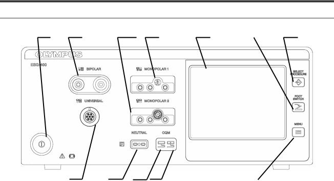
5-2 Front panel
1. |
2. |
3. |
4. |
5. |
6. |
7. |
12. |
11. |
10. |
9. |
8. |
1.Power switch
This switch turns the electrosurgical generator on and off.
2.BIPOLAR socket
This socket connects the plug of a bipolar HF instrument (applied part).
3.MONOPOLAR 2 socket
This socket connects the plug of a monopolar HF instrument (applied part).
4.MONOPOLAR 1 socket
This socket connects the plug of a monopolar HF instrument (applied part).
5.Touch-screen
Displays the connection status of the accessories and peripherals connected to the electrosurgical generator. It is also used to show and modify the output settings (e.g. mode, output power, effect) as well as to control other functions (e.g. save procedures, delete procedures).
6.FOOTSWITCH push button
This button is used to open the “Footswitch screen” to assign one or two footswitch(es) or the autostart function to a specific output socket.
7.SELECT PROCEDURE push button
This button is used to open the “Select Procedure screen” to recall saved settings.
8.MENU push button
This button is used to open the “Menu screen” to control several functions (save or delete a procedure, control the touch tone, output volume and brightness as well as other functions).
7.022.211 / ISSUE 5 |
22 / 110 |
Chapter 1: PRODUCT SPECIFICATIONs |

ESG-400
9.Contact quality monitor indicator for split neutral electrode
This indicator illuminates green if a split neutral electrode is connected and the contact resistance is within an acceptable range. The indicator illuminates red if the split neutral electrode is not connected or not applied properly (e.g. bad contact quality or partly dislocated) or no neutral electrode is connected (in both cases the activation of monopolar output is disabled).
10.Contact quality monitor indicator for non-split neutral electrode
This indicator illuminates green if a non-split neutral electrode is connected.
11.Neutral electrode socket
This socket connects the plug of a neutral electrode for monopolar application (applied part).
12.UNIVERSAL socket
This socket connects the plug of an Olympus HF instrument with HF instrument recognition (applied part).
7.022.211 / ISSUE 5 |
23 / 110 |
Chapter 1: PRODUCT SPECIFICATIONs |

ESG-400
5-3 Rear panel
1. |
2. |
1. |
3. |
|
|
|
|
|
|
|
|
|
|
|
7. |
6. |
5. |
4. |
1.Footswitch sockets
This socket connects the plug of a single or double pedal footswitch.
2.Volume control
This knob is used for adjusting the output volume.
3.Ventilation hole
Holes for air ventilation via a cooling fan; there are also ventilation holes on each side of the electrosurgical generator.
4.Equipotential bonding point
To increase electrical safety, this point is used for potential equalization. All equipment housings that come into contact with the patient are electrically connected in order to prevent low-frequency electrical currents from endangering the patient in the event of a defect in the conventional protective conductor system.
5.AC power socket
This socket serves as a connection to the mains power supply via a power cord
6.LINK-OUT socket
This socket connects the plug (14-pin) of a cable connected to peripheral equipment.
7.LINK-IN socket
This socket connects the plug (26-pin) of a cable connected to peripheral equipment.
NOTE |
|
The touch-screen messages may depend on the |
|
|
language setting of the electrosurgical generator. |
|
|
For a detailed explanation of the different types of |
|
|
sockets, refer to chapter 6 “Connection of neutral |
|
|
electrode” and chapter 3.7 “Connection of HF |
|
|
instruments”. |
7.022.211 / ISSUE 5 |
24 / 110 |
Chapter 1: PRODUCT SPECIFICATIONs |

ESG-400
5-4 Bottom panel
1.
1.Docking socket
This socket connects the plug (7-pin) of a docking connector to connect peripheral equipment. For more details, see chapter 1-6-1.
5-5 |
All screen |
1. |
2. |
3. |
4. |
5. |
6.
7.
8.
12. |
9. |
11.
10.
1.Reference to output sockets indicator
This indicator shows the corresponding output socket where the same symbol is printed on the front panel.
2.Output socket name
The name of the corresponding output socket is displayed here.
3.Autostart indicator
This symbol indicates if the autostart function is assigned to the corresponding output socket. Blank if
7.022.211 / ISSUE 5 |
25 / 110 |
Chapter 1: PRODUCT SPECIFICATIONs |

ESG-400
autostart or footswitch is not assigned. Refer to chapter 6.4, “Assign footswitch and autostart function”.
4.Procedure name
The name of the selected procedure is displayed here. Blank if no procedure is selected.
5.Communication indicator
This symbol indicates if communication with peripheral equipment connected to the docking socket is established.
6.Footswitch indicator (double pedal)
This symbol indicates if a connected double pedal footswitch is assigned to the corresponding output socket. Blank if autostart or footswitch is not assigned. Refer to chapter 6.4, “Assign footswitch and autostart function”.
7.Output mode
The name of the output mode as selected in the “Mode screen” is displayed here. If “Off” is selected, “--“ will be displayed instead of power level and effect.
8.Output power level
The number shows the output power level as selected in the “Set screen”. If an output power level is set to zero, “--” will be displayed instead of numbers.
9.Effect
The number shows the effect as selected in the “Set screen”. For RFCoag mode the RCAP function can be selected instead of an effect (refer to chapter 5.3, “Output setting”).
10.Button area
Each button covers the entire area including all output socket related information as described above (3. to 10.). Press the button, to switch to the corresponding “Set screen” to select the mode, power levels and effects for the corresponding output socket.
11.Footswitch indicator (single pedal)
This symbol indicates if a connected single pedal footswitch is assigned to the corresponding output socket. Blank if autostart or footswitch is not assigned. Refer to chapter 6.4, “Assign footswitch and autostart function”.
12.UNIVERSAL / Instrument name
The name of the instrument or cable will be displayed instead of the output socket name “UNIVERSAL” if an instrument or cable with instrument recognition is connected to the UNIVERSAL socket.
5-6 Set screen
1.
5. |
|
2. |
|
|
|
|
|
3. |
6. |
2 |
4. |
1.Mode button
The name of the output mode as selected in the “Mode screen” is displayed here. Press this button to switch to the “Mode screen”. If “Off” is selected,
“--“ will be displayed instead of power level and effect.
2.Plus button / Minus button
These buttons increase / decrease the output power level.
7.022.211 / ISSUE 5 |
26 / 110 |
Chapter 1: PRODUCT SPECIFICATIONs |

ESG-400
3.Toggle button
This button switches to the next effect.
4.Return button
Press this button to save the settings and to return to the “All screen.”
5.Output power level
The number shows the selected output power level. If an output power level is set to zero, “--” will be displayed instead of numbers.
6.Effect
The number shows the selected effect. For RFCoag mode the RCAP function can be selected instead of an effect (refer to chapter 5.3, “Output setting”)
5-7 Mode screen
1.
3. |
2. |
1.Mode button
These buttons allow the mode selection for a corresponding output socket as shown in the title line. If a selection is already activated, this is indicated by a gray button. If no mode shall be selected, press the “Off button.”
2.Return button
Press this button to return to the “Set screen.”
3.Arrow button
Optional buttons to browse through the mode list. They are disabled if the number of available modes fit to one screen.
7.022.211 / ISSUE 5 |
27 / 110 |
Chapter 1: PRODUCT SPECIFICATIONs |
ESG-400
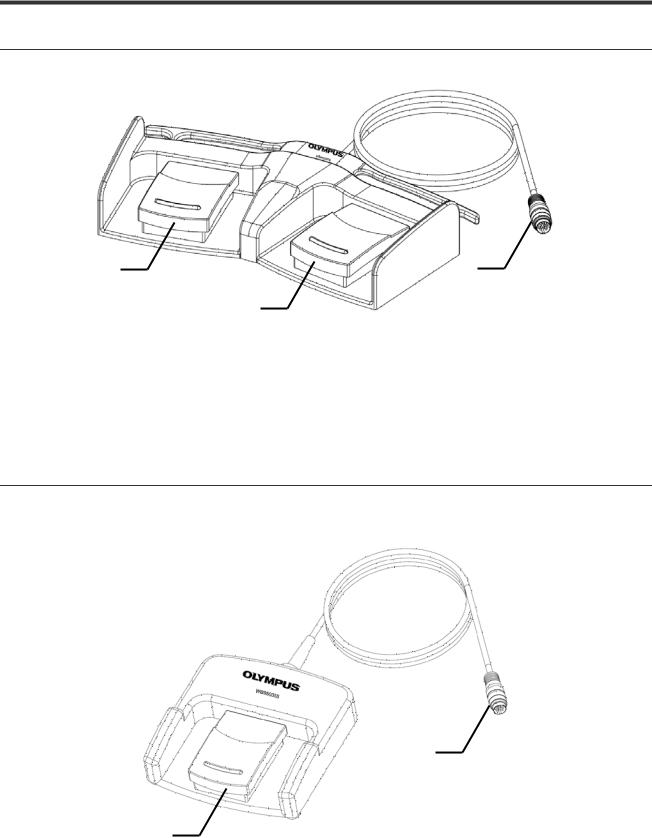
5-8 Footswitch with two pedals
The footswitch with two pedals (Olympus REF: WB50402W) is included in delivery.
1. |
3. |
2.
1.Cut pedal (yellow color)
This pedal is used to activate the selected cutting mode.
2.Coagulation pedal (blue color)
This pedal is used to activate the selected coagulation mode.
3.Footswitch plug
Connects the footswitch with the electrosurgical generator on the rear panel.
5-9 Footswitch with one pedal (optional)
The footswitch with one pedal (Olympus REF: WB50403W) is an optional item which may be purchased separately.
2.
1.
1.Coagulation pedal (blue color)
This pedal is used to activate the selected coagulation mode.
2.Footswitch plug
Connects the footswitch with the electrosurgical generator on the rear panel.
7.022.211 / ISSUE 5 |
28 / 110 |
Chapter 1: PRODUCT SPECIFICATIONs |

ESG-400
5-10 Neutral electrode cable “P-cord” (optional)
The neutral electrode cable “P-cord” (Olympus REF: MAJ-814) is an optional item for the connection with a neutral electrode which may be purchased separately.
1.
3.
2.
1.Lever-locking arm
This arm secures the connector of the neutral electrode with the clamp.
2.Clamp
This clamp connects the neutral electrode to the “P-cord”.
3.Plug on the electrosurgical generator side
This plug connects the “P-cord” to the electrosurgical generator.
7.022.211 / ISSUE 5 |
29 / 110 |
Chapter 1: PRODUCT SPECIFICATIONs |

ESG-400
6 Connector
6-1 Docking Connector
1)BNE – Bipolar Neutral Electrode
2)BAE – Bipolar Active Electrode
3)MAE – Monopolar Active Electrode
4)Common CD – Common ground for connection detection
5)MAPCAE – Monopolar Active Electrode
11)CD APC – Active pin for connection detection
12)CD NEO – Active pin for connection detection
Pinning of connector 13 Docking
Connector - view of connector side (bottom view) of ESG-400
6-2 |
Monopolar Standard 1 |
||
Type: |
|
3 pin Valleylab, pin diameter = 4mm |
|
|
|
1 pin BOVIE, pin diameter = 8 mm |
|
Function: |
|
Monopolar output |
|
|
|
Finger switch input (only for Valleylab: cut and coag) |
|
|
|
4 |
1 Hand Cut |
|
|
|
|
1 |
|
|
2 Hand Coag |
|
3 |
3 Active electrode |
|
|
2 |
4 Active electrode |
|
|
|
||
|
|
|
|
6-3 |
Monoploar Standard 2 (Erbe) |
||
Type: |
|
3 pin Valleylab, pin diameter = 4mm |
|
|
|
Coaxial ERBE, pin diameter = 5 mm (inner) and 9 mm (outer) |
|
Function: |
|
Monopolar output |
|
|
|
Finger switch input (cut and coag) |
|
|
|
4 |
1 Hand Cut |
|
|
|
|
|
|
|
2 Hand Coag |
1 |
|
|
3 Active electrode |
|
2 |
3 |
4 Cut+Coag+Active electrode (top) |
6-4 |
Bipolar Standard 3 |
Type: |
2 pin socket, pin diameter = 4mm / pin distance 28.8 mm |
|
Coaxial socket, pin diameter = 4 mm (inner) and 8 mm (outer) |
7.022.211 / ISSUE 5 |
30 / 110 |
Chapter 1: PRODUCT SPECIFICATIONs |
Loading...