


INSTRUCTIONS
DP21
MICROSCOPE DIGITAL CAMERA
This instruction manual is for the Olympus Microscope Digital Camera Model DP21.
To ensure the safety, obtain optimum performance and familiarize yourself fully with the use of this camera, we recommend that you study this manual thoroughly before operating the camera. Retain this instruction manual in an easily accessible place near the work desk for future refer-
ence. |
A X 7 9 3 1 |

Notations Used in This Manual
This system is used either in a standalone (SAL) or PC-connection (PC) configuration.
Each page of this manual carries one of notations “Common,” “SAL” and “PC” on the top right to indicate the applicable configuration of the descriptions in it. Please read the pages applicable to your configuration.
1. Important (Common) |
p.1 to p.4 |
|
|
This chapter describes the cautions related to the safety and operation of the system.
2. Standalone System (SAL) |
p.5 to p.66 |
|
|
This chapter describes the operation of the configuration in which the camera head is connected to the control box.
3. PC Connection System (PC) |
p.67 to p.81 |
|
|
This chapter describes the operation of the configuration in which the camera head is connected to a desktop or laptop PC.
4. General (Common) |
p.82 to p.87 |
|
|
This chapter describes the specifications and troubleshooting information.
This device complies with the requirements of both directive 2004/108/EC concerning electromagnetic compatibility and directive 2006/95/EC concerning low voltage.
In accordance with European Directive 2002/96/EC on Waste Electrical and Electronic Equipment, this symbol indicates that the product must not be disposed of as unsorted municipal waste, but should be collected separately.
Refer to your local Olympus distributor in EU for return and/or collection systems available in your country.
NOTE: This equipment has been tested and found to comply with the limits for a Class A digital device,
pursuant to Part 15 of the FCC Rules. These limits are designed to provide reasonable protection
against harmful interference when the equipment is operated in a commercial environment. This
equipment generates, uses, and can radiate radio frequency energy and, if not installed and used in
accordance with the instruction manual, may cause harmful interference to radio communications.
Operation of this equipment in a residential area is likely to cause harmful interference in which case
the user will be required to correct the interference at his own expense.
FCC WARNING: Changes or modifications not expressly approved by the party responsible for compliance
could void the user’s authority to operate the equipment.
CALIFORNIA USA ONLY
This control box uses a Lithium Battery which contains Perchlorate Material - special handling may apply, See www.dtsc.ca.gov/hazardouswaste/perchlorate.

CONTENTS
1 |
IMPORTANT (Common) |
|
1-4 |
||||
|
|
|
|
|
|
||
|
1-1 |
Safety Precautions ................................................................................................................................................................................. |
|
|
1 |
||
|
1-2 |
Conformity of the System ............................................................................................................................................................ |
|
2 |
|||
|
1-3 |
Getting Ready ............................................................................................................................................................................................... |
|
|
3 |
||
|
1-4 Maintenance and Storage.......................................................................................................................................................... |
|
3 |
||||
|
1-5 |
Caution ................................................................................................................................................................................................................... |
|
|
4 |
||
|
|
|
|
||||
2 |
Standalone System (SAL) |
|
5-66 |
||||
|
|
|
|
|
|||
|
2-1 |
Operating Precautions ............................................................................................................................... |
|
............................... 5,6 |
|||
|
2-2 |
System Chart ................................................................................................................................................................................................. |
|
|
7 |
||
|
2-3 |
Nomenclature............................................................................................................................... |
|
...................................................... |
8-11 |
||
|
|
2-3-1 |
Hardware controls.............................................................................................................................................................................................................. |
|
|
8,9 |
|
|
|
2-3-2 |
MENU / INFO display.............................................................................................................................................................................................. |
|
10,11 |
||
|
2-4 |
Installation ............................................................................................................................................................................................. |
|
|
11-16 |
||
|
2-5 |
Basic Image Recording Procedure ................................................................................................................. |
17-24 |
||||
|
|
2-5-1 |
Operation flow ............................................................................................................................... |
|
................................................................................ |
17-24 |
|
|
|
1 |
Turning Power ON/OFF ...................................................................................................................................................................................................... |
|
18 |
||
|
|
2 |
Initial Setting ....................................................................................................................................................................................................................................... |
|
|
19 |
|
|
|
3 |
Selecting the Mode ................................................................................................................................................................................................................ |
|
|
20 |
|
|
|
4 |
Viewing/Hiding the INFO Display....................................................................................................................................................................... |
20 |
|||
|
|
5 |
Viewing/Controlling the MENU Display .................................................................................................................................................... |
21 |
|||
|
|
6 |
Setting the Live Resolution |
Default: 1600 x 1200 ......................................................................................................... |
22 |
||
|
|
7 |
OTWB (One-Touch White Balance) ................................................................................................................................................................. |
22 |
|||
|
|
8 |
Recording Still Images ...................................................................................................................................................................................................... |
|
23 |
||
|
|
9 |
Recording Movies ..................................................................................................................................................................................................................... |
|
|
24 |
|
|
2-6 |
Recording Function Setting/Operation (REC)................................................................................. |
25-48 |
||||
|
|
2-6-1 |
Operation using the hand switch ................................................................................................................................................... |
25-48 |
|||
|
|
1 |
Available Functions............................................................................................................................... |
|
.................................................................................. |
25 |
|
|
|
2 |
Exposure Adjustment |
............................................................................................................................... |
........................................................................... |
26 |
|
|
|
3 |
SPOT Metering Setting ............................................................................................................................... |
....................................................................... |
26 |
||
|
|
4 |
AE Lock Setting ............................................................................................................................... |
|
............................................................................................. |
27 |
|
|
|
5 |
Zooming/Scrolling ............................................................................................................................... |
|
.................................................................................... |
27 |
|
|
|
6 |
Composite Button Operations ............................................................................................................................... |
................................................ |
28 |
||
|
|
2-6-2 |
Operation using the MENU display.............................................................................................................................................. |
29-33 |
|||
|
|
1 |
Viewing the MENU Display............................................................................................................................... |
........................................................... |
29 |
||
|
|
2 |
Image Quality Mode Setting |
Default: HQ..................................................................................................................................... |
30 |
||
|
|
3 |
ISO Speed Setting |
Default: 100.................................................................................................................................................................. |
30 |
||
|
|
4 |
Sharpness Setting |
Default: NORMAL ................................................................................................................................................ |
30 |
||
|
|
5 |
Save Folder Setting |
Default: AUTO.............................................................................................................................................. |
31,32 |
||
|
|
6 |
White Balance (WB) Mode Setting Default: AUTO ......................................................................................................... |
33 |
|||
|
|
7 |
Folder and File Names ............................................................................................................................... |
....................................................................... |
33 |
||
|
|
2-6-3 |
Applied operations............................................................................................................................... |
|
................................................................. |
34-48 |
|
|
|
1 |
Manual recording ............................................................................................................................... |
|
....................................................................................... |
34 |
|
|
|
2 |
REC VIEW Setting |
Default: 5 sec. ............................................................................................................................................................ |
34 |
||
|
|
3 |
Image Color Setting |
Default: COLOR-1 .......................................................................................................................................... |
34 |
||
|
|
4 |
Scale Display Setting |
Default: OFF ........................................................................................................................................ |
35-37 |
||

|
|
|
|
|
|
5 |
Scale Display Range Setting |
..................................................................................................Default: LIVE & SNAP |
37 |
|
6 |
Image Orientation Setting |
Default: Erect............................................................................................................................... |
....... 37 |
|
7 |
Focusing indicator Setting |
Default: OFF ........................................................................................................................... |
37,38 |
|
8 |
AE Area Display Setting Default: OFF ............................................................................................................................................... |
39 |
|
|
9 |
Measurement Functions ............................................................................................................................... |
..................................................... |
39-48 |
|
10 |
Cross lines display ............................................................................................................................... |
................................................................................... |
48 |
2-7 |
Playback Function Setting/Operation (PLAY) ................................................................................... |
49-52 |
||
|
1 |
Selecting the Mode ............................................................................................................................... |
................................................................................. |
49 |
|
2 |
Viewing/Hiding the INFO Display....................................................................................................................................................................... |
49 |
|
|
3 |
Selecting the Played Image ............................................................................................................................... |
........................................................ |
49 |
|
4 |
Selecting the Played Movie ............................................................................................................................... |
......................................................... |
50 |
|
5 |
Zooming/Scrolling ............................................................................................................................... |
.................................................................................... |
50 |
|
6 |
Viewing the Index Display ............................................................................................................................................................................................. |
|
51 |
|
7 |
Erasing an Image ............................................................................................................................... |
....................................................................................... |
52 |
|
8 |
Protecting an Image ............................................................................................................................... |
............................................................................... |
52 |
|
9 |
Measuring a Played Image ............................................................................................................................... |
.......................................................... |
52 |
2-8 |
MENU Display Functions ............................................................................................................................... |
............... |
53-59 |
|
|
1 |
Media Setup ............................................................................................................................... |
....................................................................................................... |
53 |
|
2 |
Date/Time Setting ............................................................................................................................... |
...................................................................................... |
53 |
|
3 |
Reset ............................................................................................................................... |
............................................................................................................................. |
54 |
|
4 |
Recorded Folder Setting ............................................................................................................................... |
.................................................................. |
54 |
|
5 |
Options........................................................................................................................................................................................................................................... |
|
54,55 |
|
6 |
Maintenance Setting ............................................................................................................................... |
................................................................ |
55-58 |
|
7 |
Operation Using Mouse and Keyboard.................................................................................................................................................... |
59 |
|
2-9 |
Functions Interlocked with Microscope Operations ............................................................. |
60-66 |
||
|
2-9-1 System chart................................................................................................................................................................................................................................ |
|
60 |
|
|
2-9-2 Connection ........................................................................................................................................................................................................................ |
|
61-63 |
|
|
2-9-3 Operation ............................................................................................................................................................................................................................. |
|
64-66 |
|
3 |
PC Connection System (PC) |
67-81 |
|
|
|
|
|
|
3-1 |
Operating Precautions ................................................................................................................................................................ |
67 |
|
3-2 System Chart ............................................................................................................................................................................................. |
68 |
|
|
3-3 Nomenclature........................................................................................................................................................................................... |
69 |
|
|
3-4 |
Installation ............................................................................................................................................................................................ |
70,71 |
|
3-5 |
DP2-TWAIN Software Installation........................................................................................................................ |
72-78 |
|
3-6 Image Recording Procedure Using DP21-TWAIN ................................................................................. |
79 |
|
|
3-7 Displayed Windows of DP2-TWAIN........................................................................................................................... |
80 |
|
|
3-8 |
DP2-TWAIN Software Uninstallation......................................................................................................................... |
81 |
|
|
|
|
4 |
GENERAL (Common) |
82-87 |
|
|
|
|
|
|
4-1 Warning Messages .......................................................................................................................................................................... |
82 |
|
|
4-2 |
Specifications ................................................................................................................................................................................. |
83,84 |
|
4-3 |
Troubleshooting Guide .................................................................................................................................................... |
85-87 |
|
4-4 |
Index ............................................................................................................................................................................................................ |
88,89 |
|
....................................................................PROPER SELECTION OF THE POWER SUPPLY CORD |
90,91 |
1 IMPORTANT (COMMON)
Common
The DP21 microscope digital camera is designed to be connected to a camera adapter mounted on an Olympus UIS2/UIS series microscope for use in recording of microscopic magnified image of the optical microscope.
When the DP21 is used with a camera adapter from other manufacturer than Olympus, the optical performance may not be manifested fully.
1-1 Safety Precautions
1.Before connecting or disconnecting a connection cable or power cord, make sure that the main switch of the control box is set to OFF.
When connecting the cable or power cord, push in the connector all the way before pressing the main switch to ON.
CAUTION To avoid electric shock or equipment failure, never connect or disconnect a cable while the main switch is set to ON.
2.Always use the AC adapter provided by Olympus.
Using a similar but non-Olympus AC adapter does not only allow the camera to manifest its full performance but may also cause an equipment failure as well as a burn or fire hazard due to abnormal heating. Never use such an AC adapter.
3.The cords and cables are vulnerable to bend or twist. Do not apply excessive force to them.
Also distribute the cords and cables away from a heat-generating part such as the lamp housing of the microscope.
4.To prevent the microscope from toppling down, avoid using microscope attachments that may make the total height of the microscope above 1 meter when they are attached.
5.The AC adapter, camera head, control box and USB memory generate heat after they have been used for a long period of time.
To avoid moderate temperature burn, do not leave these parts in extended contact with your skin.
6.Connect the power cord correctly and ensure that the grounding terminals of the power supply and wall outlet are properly connected. If the equipment is not grounded/earthed, Olympus can no longer warrant the electrical safety performance of the equipment.
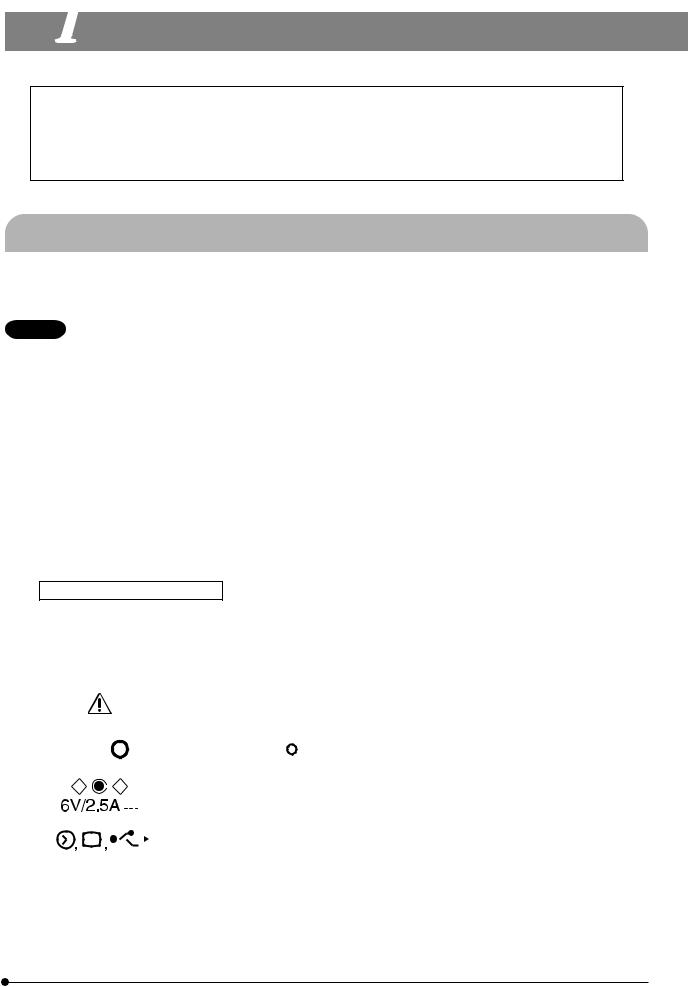
Safety and Operation Symbols
The following symbols are found on the control box, hand switch and camera head. Study the meaning of the symbols and always use the equipment in the safest possible manner.
|
|
|
|
Symbol |
|
|
Explanation |
||||||||||||||
|
|
|
|
|
|
|
|
|
|
|
|
|
|
|
|
|
|
|
|
|
|
|
|
|
|
|
|
|
|
|
|
|
|
|
|
|
|
|
|
|
Before use, carefully read the instruction manual. Improper use could result in personal injury |
||
|
|
|
|
|
|
|
|
|
|
|
|
|
|
|
|
|
|
|
to the user and/or damage to the equipment. |
||
|
|
|
|
|
|
|
|
|
|
|
|
|
|
|
|
|
|
|
|
|
|
|
|
|
|
, |
|
|
|
|
|
|
|
|
|
|
|
Indicates “ |
|
” (ON) or “ ” (OFF) of the main switch. |
|||
|
|
|
|
|
|
|
|
|
|
|
|
|
|
|
|
||||||
|
|
|
|
|
|
|
|
|
|
|
|
|
|
|
|
|
|
||||
|
|
|
|
|
|
|
|
|
|
|
|
|
|
|
|
|
|
|
|
|
|
|
|
|
|
|
|
|
|
|
|
|
|
|
|
|
|
|
|
|
Use the specified AC adapter (6 V, 2.5 A DC) |
||
|
|
|
|
|
|
|
|
|
|
|
|
|
|
|
|
|
|
|
|||
|
|
|
|
|
|
|
|
|
|
|
|
|
|
|
|
|
|
|
|
|
|
|
|
|
|
|
|
|
|
|
|
|
|
|
|
|
|
|
|
|
Symbols representing an input connector, display, and USB connector respectively. |
||
|
|
|
|
|
|
|
|
|
|
|
|
|
|
|
|
|
|
|
|||
|
|
|
|
|
|
|
|
|
|
|
|
|
|
|
|
|
|
|
|||
|
|
|
|
|
|
|
|
|
|
|
|
|
|
|
|
|
|
|
|||
|
|
|
|
|
|
|
|
|
|
|
|
|
|
|
|
|
|
|
|
|
|
1394 |
|
|
|
|
|
Symbol of camera cable (1394) connector. |
|||||||||||||||
|
|
|
|
|
|
|
|
|
|
|
|
|
|
|
|
|
|
|
|
|
|
1

1-2 Conformity of the System
Restrictions in Use
1.The standard TV adapters are the U-TV1X-2 and U-TV0.5XC-3.
The U-TV0.25xC, U-TV0.35xC (or a TV adapter with magnification below 0.5X), U-TV0.5XC and GX-TV0.5XC-DP cannot be used because of optical performance problems.
2.When the DP21 is connected to the rear port of the U-DPT or U-MPH, the peripheral part of the recorded image may be deteriorated due to the optical performance of the U-DPT or U-MPH.
3.When two or more intermediate attachments are used, the peripheral part of the image may become dark or obscured depending on the observation tube and objective in use.
4.When a fluorescent lamp illumination or an illumination stand of the SZX/SZX2 series is used, the image may flicker.
5.When a non-Olympus microscope or a commercially available C-mount lens is used, problems due to the optical adaptability such as shading may be observed. If a commercially available C-mount lens is used, the thread projection and lens projection from the C-mount body attaching section should be no more than 4.5 mm.
6.When the specimen has a low contrast (near transparent) or high reflectance (mirror status) and the aperture iris diaphragm is stopped down near the smallest aperture, spot flare may be noticeable.
7.When the edge of a non-transmitting object is observed under the STM6 transmitted illumination, flare may be noticeable due to the difference in brightness between the transmitted sections (over-exposure) and non-transmitting section (underexposure).
To reduce the flare, set a lower exposure using the exposure adjustment function or setting the exposure manually. (Details of STM6 combination)
Edge observation using the MM6-OB3X/5X/10X objective in combination with the MM6C-VL/MM6-ETR
8.When the SZX16 is combined, the peripheral brightness may become insufficient with a zoom ratio of no more than 10x.
9.The image of dark specimens under reflected light or in the darkfield (specimens that need exposure of 1/2 sec. or more at ISO 100 equivalent) cannot be recorded.
10.Specimens with a distribution that is not suitable for center averaged metering require spot metering or exposure adjustment.
11.When electronic zoom is used for magnification display during focusing, the image may become noticeably coarse with certain samples.
12.The live image frame rate of 15 fps is possible when the exposure time is no more than 1/15 sec.
13.When the scale recording function or measurement function is used, the image capturing time becomes longer than usual.
14.The trackability of auto white balance control deteriorates when the specimen contains little white area.
15.The measurement results are simply superimposed on the image and no text file or like is created.
16.The DP21 can handle files of the FAT and FAT32 formats only, and it is not compatible with other file formats. When using a recording medium of an incompatible format, it is required to convert the format into FAT or FAT32 using a PC.
17.It is not possible to use a special USB memory adopting the security or password lock function.
18.To prevent destruction of the recorded image (data), never perform the following action during recording of a still image or movie;
·turning power OFF;
·disconnecting the AC adapter;
·disconnecting the recording medium such as the USB memory or LAN cable.
Operating Environment
Temperature: 5 to 35°C. Humidity: 20% to 85% (without condensation).
Recommended Monitor Specifications
A monitor with the 800 x 600 or larger full-color display capability (the factory setting is WUXGA 1920 x 1200). Compliance to the VESA DDC2B standard.
2

Common
1-3 Getting Ready
1.The camera head uses precision components. Handle it with care and avoid subjecting it to a sudden or severe impact.
2.The image displayed on the monitor may be affected when it is used near equipment generating strong electromagnetic waves. To avoid interference during operation, keep the system far from any source of electromagnetic waves.
3.Do not use the camera in areas where it may be subjected to direct sunlight, high temperature and humidity, dust or vibrations. (For the operating environment conditions, see “SPECIFICATIONS” on page 83.)
1-4 Maintenance and Storage
1.To clean the lenses and other glass components, simply blow dirt away using a commercially available blower and wipe gently using a piece of cleaning paper (or clean gauze).
If a lens is stained with fingerprints or oil smudges, wipe it with gauze slightly moistened with commercially available absolute alcohol.
CAUTION Since the absolute alcohol is highly flammable, it must be handled carefully. To prevent fire ignition, be sure to keep it away from open flames or potential sources of electric sparks -- for example, electrical equipment that is being switched on or off.
Also remember to always use these chemicals only in a well-ventilated room.
2.Parts other than the glass components should be cleaned by wiping with a clean cloth. Do not use organic solvents to remove major stains. Use a soft cloth slightly moistened with a neutral detergent solution.
3.Do not disassemble any part of the camera as this could result in malfunction or reduced performance.
4.When the system is not used, store it with the dust cover. Before storage, ensure that the main switches of the DP21’s control box and the microscope are set to OFF and that the lamp housing is cool enough.
5.When smoking the room for cleaning, etc., move the DP21 to a place not exposed to smoke.
6.Care is required against condensation as this may sometimes cause malfunction. Condensation is the phenomenon in which the vapor in the air is condensed into water drops, which attach to the surface of a metallic plate, etc. It often occurs when the ambient temperature changes suddenly, for example when a camera is brought from cold outdoors into warm indoors.
3

1-5 Caution
If the equipment is used in a manner not specified by this manual, the safety of the user may be imperiled. In addition, the equipment may also be damaged. Always use the equipment as outlined in this instruction manual.
The following symbols are used to set off text in this instruction manual.
CAUTION : Indicates a potentially hazardous situation which, if not avoided, may result in minor or moderate injury or damage to the equipment or other property. It may also be used to alert against unsafe practices.
}: Indicates commentary (for ease of operation and maintenance).
Caution on Image Data Storage
The recorded image data may be lost (destroyed) in the following cases. Note that Olympus will not assume any liabilities for the loss (destruction) of recorded data.
The image data may also be destroyed by an unexpected cause. It is recommended to back up the data periodically.
·When the user or a third party used the USB memory in a wrong way.
·When the user or a third party services or repairs the equipment.
·When the USB memory is affected by static electricity or electromagnetic noise.
·When the USB memory is unplugged, the main switch is set to OFF, the AC adapter is disconnected or the power cord is unplugged during recording or erasure (formatting) of the USB memory.
·When the equipment fails.
Note on Disposal
Be sure to observe your local regulations and rules when disposing of this product. Special care is required for the control box because it incorporates a lithium manganese coin battery (CR2032). If you have any doubt, please consult Olympus.
4

 STANDALONE SYSTEM (SAL)
SAL System
Read this chapter if you use the camera head by connecting it to the control box.
2-1 Operating Precautions
System Compatibility
· Only the following USB devices function when connected to the control box, etc. Connectable USB devices: USB removable media such as a USB memory
USB mouse USB keyboard
·Even when one of the USB devices is used, it cannot be connected if it needs a special driver or the Explorer function of the PC for operation.
·When a USB device with current consumption above 200 mA (including a USB memory, mouse or keyboard) is connected, it may not function due to insufficient power supply from the hand switch.
·The network connection requirements are as follows.
Applicable PC: DOS/V AT compatible machine
Applicable OS: Windows XP Professional/Vista Business (32-bit)/Vista Ultimate (32-bit) Standards: IEEE802.3 (10BASE-T Ethernet),
IEEE802.3u (100BASE-TX Fast Ethernet) compliant Applicable protocol: TCP/IP (Incompatible with IPv6) Connector: RJ-45 type 8-pole connector
Transmission rate: 10 Mbps (10BASE-T Ethernet)/100 Mbps (100BASE-TX Fast Ethernet)
Even when the connection requirements above are met, connection and operation in any network environment is not guaranteed.
Computer Virus Note
As a countermeasure against computer viruses, the DP21 is set to inhibit write of foreign files in the system domain. Nevertheless, it is not capable of preventing infection by computer viruses that are evolving day by day. To prevent penetration of computer viruses in the DP21, it is also recommended to take the following countermeasures.
·Perform virus check on the removal medium, such as a USB memory, before connecting it to the DP21. (The DP21 does not have the virus check function. Use your PC for virus checking.)
·Ensure that the network and PC to which the DP21 is connected are free of computer viruses.
·Should infection of a computer virus occur or be suspected, turn the control box of the DP21 OFF and unplug its power cord. This clears the RAM and deletes any foreign files.
·If malfunction or a symptom of infection still persists after the above measure, please consult Olympus. Olympus will not assume any liabilities for a malfunction of the DP21 due to computer viruses as well as any trouble or damage of the user’s PC or network incurred due to computer viruses.
5

Battery Life
The DP21’s control box incorporates a lithium ion coin battery (CR2032) for backing up the calendar function. The service life of the battery is 1 to 6 years (it is widely variable because the battery power consumption is reduced during operation connecting the AC adapter to the control box). The camera can be used even after the battery life has expired, but the calendar is reset every time the AC adapter is unplugged.
For the battery replacement, contact Olympus.
Control Box Fan
The control box has a ventilation fan. Be careful not to block the ventilation opening. To ensure sufficient ventilation, install the control box at a distance of 10 cm or more from an obstacle such as a wall.
Blocking the ventilation opening will result in malfunction or damage. Additional care is also required against penetration of a foreign object through the ventilation opening because this may result in the fan damage. The rotation speed of the control box fan varies depending on the system internal temperature. As a result, the fan noise may increase in the following cases but this is not malfunction.
·When the ambient temperature is high in summer, etc.
·When the system temperature is high after long hours of use, etc.
·About 10 seconds after startup.
6

SAL System
2-2 System Chart
SAL (Standalone) System
}If you use a PC (PC connection) system, read from page 67.
Camera head |
|
Control box |
|
|
D21-CB |
Control box for |
|
D21-CU |
Camera cable |
|
|
|
|
coded units |
|
|
|
|
|
|
|
|
· U-CBS |
|
|
|
· U-CBM |
|
|
|
· BX3-CBH |
|
|
AC adapter |
|
|
|
|
Power cord |
|
|
Display cable |
|
|
|
LAN cable |
Monitor display |
|
|
|
|
|
USB memory |
|
|
|
|
|
To network |
|
|
Keyboard |
|
|
|
Hand Switch |
|
|
|
D21-HS |
|
|
|
Mouse |
|
|
GX-TV0.5XC |
|
U-CMAD3 |
C-mount |
|
Camera |
|
|
C-mount |
|
|
Adapter |
|
|
Camera |
|
|
GX-TV0.7XC |
|
|
Adapter |
|
|
|
C-mount |
|
|
Camera |
C-mount |
|
Adapter |
|
|
lens |
|
|
|
U-TV0.5X |
U-TV1X-2 |
U-TV0.5XC-3 |
U-TV0.63XC |
MVX-TV0.63XC |
Camera |
Camera |
C-mount |
C-mount |
|
Adapter |
Adapter |
Camera |
Camera |
C-mount |
0.5X |
1X |
Adapter |
Adapter |
Camera |
|
|
|
|
Adapter |
|
|
|
|
MVX-TV1XC |
|
|
|
|
C-mount |
|
|
|
|
Camera |
|
|
|
|
Adapter |
|
AX80/AX70 |
|
|
|
|
|
BX63/BX61 |
|
SZX16/SZX10 |
|
|
|
BX53/BX51 |
|
|
GX71/GX51 |
|
|
BX46/BX43/BX41 |
|
SZX12/SZX9 |
|
|
|
|
STM6 |
Inverted |
||
IX81/IX71/IX51 |
CX41/CX31 |
|
SZX7/SZ61 |
||
MVX10 |
Measuring |
Metallurgical |
|||
Inverted |
MX80/MX50/MX40 |
Stereo |
Microscope |
Microscope |
|
Microscope |
MX61L/MX61/MX51 |
|
Microscope |
||
Erected Microscope |
|
|
|
||
|
|
|
|
|
(Note 1) Certain microscopes are also applicable even when they are not mentioned above. Please consult Olympus for details.
(Note 2) Image color setup matching the microscope is required for faithful color reproduction (see page 34 for details).
7

2-3 Nomenclature
2-3-1 Hardware controls
CAUTION Any equipment connected to the camera head should be an Olympus-designated product or a product in compliance with the requirements of IEC60950 or CISPR22/24. If equipment other than these products is connected, Olympus cannot guarantee any performance of the camera.
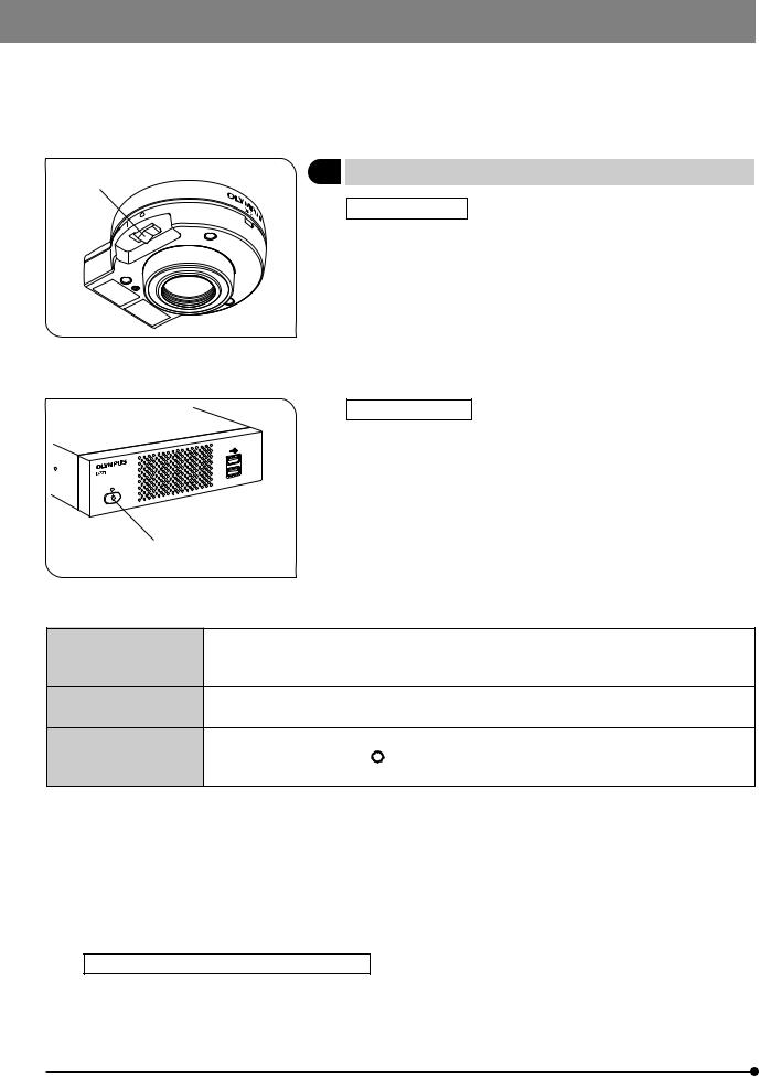
Camera Head
Main switch
Pilot LED
Camera cable connector |
|
C-mount thread |
Hand Switch
AE LOCK button |
USB port |
ACCESS LED |
|
||
(PROTECT button) |
|
STANDBY LED |
|
|
|
SPOT button |
|
Standby switch |
EXPOSE button
OTWB button (ERASE button)
SHIFT button
MODE button
MENU button
SET/OK button
Cursor buttons
8

SAL System
Control Box
Front view
Pilot LED
Main switch
Rear view
DC IN connector
Display connector
DVI-I/-D/-A
RS232C connector
For connection of the
control box (U-CBS, etc.) USB ports
Stabilizer for Vertical
Installation Stabilizer
With 2 clamp screws
Camera Cable
Camera head 
USB ports
LAN cable connector
Camera cable connector
 Control box
1394b connector (9-pin)
9
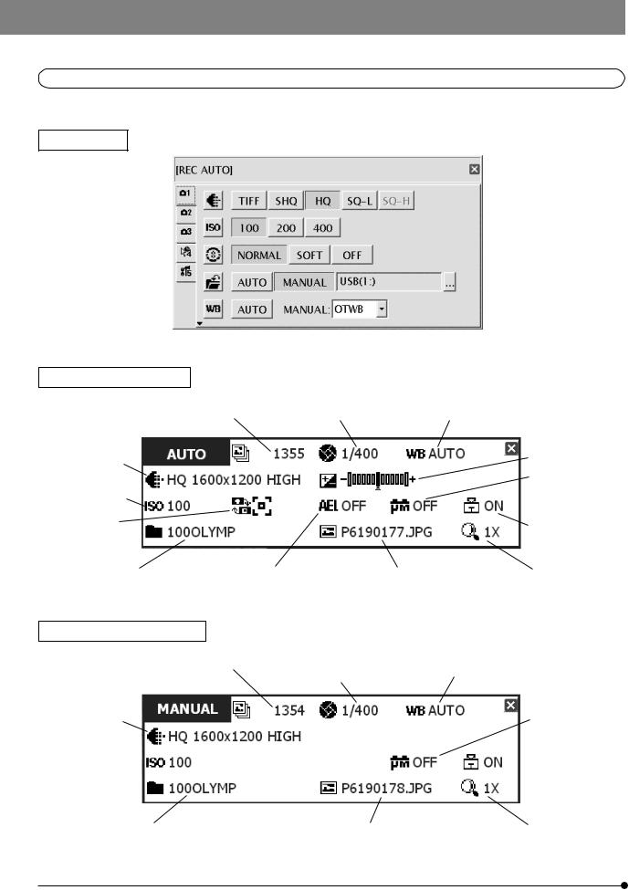
2-3-2 MENU / INFO display
MENU display
INFO display (REC AUTO)
|
No. of remaining image |
Exposure |
White balance (p. 33) |
|
|
|
(p. 23) |
time |
|
|
|
|
|
|
|
||
Image |
|
|
|
|
Exposure |
|
|
|
|
adjustment (p. 26) |
|
quality (p. 30) |
|
|
|
|
|
|
|
|
|
|
|
|
|
|
|
|
Scale setting |
ISO speed (p. 30) |
|
|
|
|
(p. 35) |
|
|
|
|
|
|
Metering |
|
|
|
|
Scale display area |
area (p. 26) |
|
|
|
|
|
|
|
|
|
(p. 37) |
|
|
|
|
|
|
|
Folder name (p. 31) |
AE lock (p. 27) |
|
File name (p. 33) |
Zoom (p. 27) |
|
INFO display (REC MANUAL)
No. of remaining image |
Exposure |
White balance (p. 33) |
|
(p. 23) |
time (p. 34) |
||
|
Image
quality (p. 30) Scale setting (p. 35)
ISO speed (p. 30) 
 Scale display area (p. 37)
Folder name (p. 31) |
File name (p. 33) |
Zoom (p. 27) |
10
SAL System
|
|
|
|
|
|
|
|
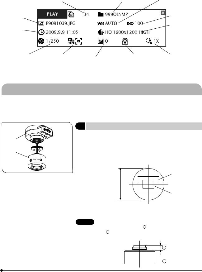
INFO display (PLAY) |
|
Recorded folder |
White balance (p. 33) |
|
Image No. |
name (p. 54) |
|
|
|||
|
|
||
File name (p. 33) |
|
ISO speed (p. 30) |
|
Date / Time |
|
Image quality |
|
|
(p. 30) |
||
(p. 53) |
|
|
|
Exposure time |
Metering area |
Exposure |
Protect (p. 52) |
Zoom (p. 27) |
(p. 34) |
(p. 26) |
adjustment (p. 26) |
|
|
If the save destination is set to a network location, the INFO display may sometimes not show the number of remaining image.
2-4 Installation
This section pertains only to the installation of the DP21 microscope digital camera.
For the installation of the combined microscope, camera adapter, etc., refer to their instruction manuals and install carefully.
1 |
Installing the Camera Head |
(Fig. 1) |
|
|
Screw in the U-TV0.5XC-3 C-mount camera adapter @ into the mount |
||
2 |
thread at the bottom of the camera head ². If you use a different C- |
||
|
mount TV adapter, follow its instruction manual. |
|
|
1 |
· As the photographed field is as shown below, use a camera adapter |
||
having magnification of 0.5X to 1X. (If a 0.35X camera adapter is used, the |
|||
|
|||
|
peripheral part of the image will be obscured.) |
|
|
Fig. 1 |
|
0.5X (FN 17.6) |
|
|
|
||
|
Field number |
|
|
|
22 |
|
|
|
|
1X (FN 8.8) |
|
·If a C-mount TV adapter from other manufacturer than Olympus is used, the optical performance of the system may not be manifested fully.
CAUTION Be careful in using other manufacturer’s C-mount camera adapter or C-mount lens a having a thread length over 4.5 mm b . Otherwise, the threaded section will hit the inside of the camera head and cause damage to it.
b
 a
a
11
1  2
2
Fig. 2
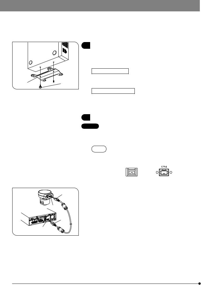
2 |
Installing the Control Box |
(Fig. 2) |
}The control box can be installed either horizontally or vertically.
}Do not place a heavy object weighing over 10 kg or an object that would make the installation unstable on the control box.
Horizontal installation
Place the control box on the desktop so that its rubber feet contact the desktop surface.
Vertical installation (Fig. 2)
Attach the stabilizer @ provided with the control box on the side of the control box using the provided screws ².
Always use the provided stabilizer for vertical installation.
3 |
Connecting the Camera Cable |
(Fig. 3) |
CAUTION · The cords and cables are vulnerable to bend or twist. Do not apply excessive force to them.
·Be sure to switch off the control box before proceeding to the connection.
NOTE When connecting the cable, insert the connector plug in the proper direction.
(Example: Camera cable)
1
2
³
|
Fig. 3
Cable side |
Connector side |
1.Insert the connector @ on one end of the camera cable into the connector ² on the camera head.
2.Insert the connector ³ on the other end of the camera cable into the connector | on the control box.
12

SAL System
|
4 |
Connecting the Display Cable |
(Fig. 4) |
|
|
|
|
Insert the connector @ of the cable provided with the display all the way |
|
|
|
|
into the connector ² on the control box and secure the clamping screws |
|
|
|
|
on both sides of the connector. |
|
|
|
}Use a DVI cable matching the display as the display cable. The DP21 is |
||
|
|
|
compatible with either the DVI-I, D or A connector. |
|
2 |
@ |
|
|
|
|
Fig. 4 |
|
|
|
@ |
5 |
Connecting the AC Adapter |
(Fig. 5) |
|
|
CAUTION · Always use the AC adapter provided by Olympus. Using other |
|||
|
|
|
AC adapter will result in malfunction or damage. |
|
³ |
5 |
|
· The cords and cables are vulnerable to bend or twist. Do not |
|
2 |
|
|
apply excessive force to them. |
|
|
|
1. |
Pass the cable of the AC adapter through the holder @ on the control |
|
|
|
|
box and close the holder @ securely. This measure is required to prevent |
|
|
| |
|
the cable from easily disconnecting from the control box. |
|
|
2. |
Insert the output connector ² of the AC adapter into the DC input con- |
||
|
|
|||
|
Fig. 5 |
|
nector ³ of the control box. |
|
CAUTION Always use the power cord provided by Olympus. If no power cord is provided with the camera head, please select the proper power cord by referring to chapter “PROPER SELECTION OF THE POWER SUPPLY CORD” at the end of this instruction manual.
3.Insert the connector | of the power cord into the input connector 5 of the AC adapter.
4.Insert the power cord plug into the power outlet. Connect the power cord correctly and ensure that the grounding terminals of the power supply and wall outlet are properly connected. If the equipment is not grounded/ earthed, Olympus can no longer warrant the electrical safety performance
of the equipment.
}The AC adapter and control box generate heat after long hours of use, but this is not malfunction.
13

|
Disconnecting the AC Adapter |
|
Press the main switch @ of the control box to shut down the DP21 and |
|
confirm that the POWER LED ² is turned off completely (about 10 sec.) |
2 |
before unplugging the connector of the AC adapter. |
|
CAUTION Unplugging the connector while POWER LED ² is lit will result |
|
in malfunction or damage. |
1
Fig. 6
 CAUTION
 Do not use the system if the AC adapter plug is inserted incompletely.
 Never plug or unplug the AC adapter plug with a wet hand.
 In the case of abnormality with the AC adapter or cord, such as abnormal heat generation, scorched smell or smoke, immediately unplug the power cord from the power outlet and stop using the system. Also contact Olympus immediately.
 Never use an AC adapter other than the designated AC adapter. Otherwise, a failure of the control box, camera head or power supply, or an incident including a fire hazard may result. Note that Olympus will not warrant damage incurred due to the use of a non-designated AC adapter.
 Never pull, bend, twist the AC adapter cord excessively or use an extension cord.
 If the AC adapter cord is scratched, the internal conductor is disconnected or the plug has a contact failure, immediately contact Olympus.
 When the system is not used, be sure to unplug the AC adapter from the power outlet.
 When connecting the power cord to a wall outlet, do not use a multioutlet extension or a table tap with multiple outlets. Otherwise, a fire hazard may result.
14

SAL System
|
|
|
|
6 |
|
|
|
Connecting the Hand Switch |
(Fig. 7) |
|
|
1 |
Insert the USB cable connector of the hand switch into one of the USB |
||
|
ports @ of the control box. |
|
|
}The control box has a total of four USB ports. The hand switch function is identical regardless of the connected USB port so the user can select any USB port as desired.
2
Fig. 7
7 |
Inserting the USB memory |
(Fig. 8) |
Insert the USB memory @ all the way into the USB port ² of the hand switch.
2
1
Fig. 8
8Applicability of USB Device
CAUTION USB memory
}Do not connect a USB device other than the USB memory provided with the DP21 into the USB port of the hand switch. Otherwise, malfunction may result. If you use a commercially available USB memory, connect it to a USB port of the control box. The USB memory provided with the DP21 can also be used by inserting it into a USB port of the control box.
}The ACCESS LED of the hand switch lights or blinks during data access (for saving the recorded image, etc.). Do not disconnect the USB memory during this period.
}The USB memory can be disconnected without special disconnection processing such as that required with a PC. The USB memory can be disconnected anytime except when the ACCESS LED of the hand switch is lighting or blinking.
}A USB memory with a special function such as the security or password function cannot be used.
15

CAUTION USB mouse/keyboard
}The USB mouse and keyboard are to be purchased separately. If you want to use them, prepare the ones that comply with the following standards or contact Olympus.
USB mouse: Should be compatible with Windows XP and USB2.0. USB keyboard: Should be compatible with Windows XP, USB2.0 and the
alphanumeric keyboard.
For the latest information, visit the Olympus website or consult Olympus. http://microscope.olympus-global.com/en/
}It is not possible to install a special driver for the mouse or keyboard in the DP21. As a result, if a device requires a special driver, only the standard functions of the device are available with the DP21.
}When using a USB keyboard or mouse, connect it to a USB port of the control box.
Connection to a LAN (Fig. 9)
1
Insert the LAN cable into the LAN connector @ on the rear of the control box.
}The LAN connection is necessary only when the DP21 needs to access
a PC on a network. It is not necessary when saving the recorded data in
a USB memory.
}For network connection, the network setting is required in addition to the LAN cable connection. See page 57 for details on the network setting.
Fig. 9
16
SAL System
2-5 Basic Image Recording Procedure
This section describes the basic operating procedure of the DP21 (from turning power ON to image recording) and the initial setting method.
The information in this section is enough for mastering the basic method for recording still images and movies.
2-5-1 Operation flow
}Perform the optical adjustments sufficiently before proceeding to the following.
}Adjust the parfocality of the microscope’s eyepieces and the monitor display using the camera adapter. (For the parfocal adjustment method, refer to the instruction manual for the camera adapter.)
Connect a USB memory. (p. 15)
Set the main switch of the control box and
@ (p. 18)
camera head to ON.
|
Initial setting (First time only) |
|
|
|
· Language setting |
|
|
|
· Scale setting |
² (p. 19) |
|
|
· Date/Time setting |
|
|
|
· Monitor resolution setting |
|
|
|
|
|
|
|
|
|
|
|
|
|
|
|
Select the REC AUTO mode. |
3 (p. 20) |
|
|
|
|
|
|
|
|
|
Note on initial setting
Before initial setting, disconnect the USB memories (including the removable media devices such as HDD) from the hand switch and/or control box. They can be reconnected after completion of restarting (auto restart) after the setting.
Set the live image resolution. 6 (p. 22)
Select the recording (TV) light path on the microscope.
Adjust the microscope brightness.
·Engage an LBD filter in the microscope light path.
·Set the microscope’s control to the “  ” marking or the voltage specified for photographing.
Confirm the focus and brightness of the specimen on the monitor screen.
Perform OTWB (One-Touch White Balance) adjust-
7 (p. 22)
ment.
Check framing (recording area).
(If the live image magnification is modified, return it to 1X.)
Press the EXPOSE button to capture and record
8 (p. 23)
image.
Tip Focusing method
·The live image magnification can be zoomed into 1x --> 2x --> 4x. Focusing will be easier at a high zoom ratio (p. 27).
·The accurate focusing can be identified easily by displaying the focusing indicator on the monitor screen (p. 37).
·If the image is too bright, dim the brightness using an ND filter(s).
(Note) If the brightness is adjusted by controlling the voltage intensity, the color temperature of the illumination may change and affect the recorded image.
·Set the image quality (p. 30), SPOT metering (p. 26), AE LOCK (p. 27) and exposure adjustment (p. 26) as required.
·The brightness and color tone of the live image displayed on the monitor may sometimes differ from those that are recorded actually.
17
1Turning Power ON/OFF
1
Turning power ON
1) Set the main switch of the camera head to “ I ” (ON).
2) Press the main switch @ of the control box to turn it ON.
Fig. 10
Turning power OFF
Press the main switch ² of the control box to turn it OFF.
|
}With the DP21 system, a main switch is provided on the hand switch, |
|
(called the standby switch), control box and camera head. The following |
|
table shows what happens when each of these main switches are set to |
|
OFF. |
|
2 |
|
Fig. 11 |
Control box |
Shuts down the system (approx. 30 sec. for startup and 10 sec. for shutdown). |
|
Once the system is shut down, it cannot be started up from the hand switch. The STANDBY LED |
|
turns off when the system is shut down. |
Hand switch |
Set the system to standby mode (approx. 10 sec. for startup and. 3 sec. for sleep). |
|
The STANDBY LED blinks in standby mode. |
Camera head |
Switches only the camera OFF. The control box and hand switch are left ON. Usually, this switch |
|
does not need to be set to “ ” (OFF). |
|
The pilot LED on the camera head lights when it is ON. |
}With the standalone system, turning the control box or hand switch OFF automatically turns the camera head OFF, so it is not required to operate the main switch of the camera head. It is recommended to leave the camera head permanently ON.
}To protect the system, it is recommended to use the main switch of the control box to shut down the system whenever possible.
}If the DP21 system is used for a long period without shutting it down, the system may sometimes resets and restarts automatically (the restart time is about 30 seconds). To protect the system, it is recommended to shut down the system periodically at an interval of about once a week.
If the camera head is switched OFF during use
If the camera head is turned OFF during use of the DP21 by accidentally setting the main switch to OFF or disconnecting the camera cable, the system detects that the camera head is not connected and displays an error message. If this happens, press the main switch of the control box to shut down the system. After this, either set the main switch of the camera head to ON or reconnect the camera cable and then press the main switch of the control box to restart the system.
18

SAL System
2 |
Initial Setting |
|
|
|
To use the system correctly, it is required to set the language and scale |
|
|
magnification at the beginning. |
|
|
Set them by following the window displayed when the system is turned |
|
|
ON for the first time. |
|
}The setting window is not displayed the next time the system is turned |
|
|
|
ON. Even when they are not set at the first time, they can be set anytime |
2 |
|
using a menu. |
1. |
The setting window appears when the system is turned ON. |
|
1 |
}Before initial setting, disconnect the USB memories (including the re- |
|
Fig. 12 |
|
movable media devices such as HDD) from the hand switch and/or con- |
|
trol box. They can be reconnected after completion of restarting (auto |
|
|
|
restart) after the setting. |
|
2. |
Set the language by following the wizard. |
|
3. |
Also set the scale magnification (magnifications of the camera adapter |
and objective in use) in the same way. The DP21 restarts after completion of the setting.
}See page 54 for the language setting and page 35 for the scale magnification setting.
}The clock setting and monitor resolution setting windows are not displayed automatically. For their setting methods, see “Date/Time Setting (p. 53)” and “Monitor resolution setting (p. 56).”
}Image recording is possible even when the date/time are not set, but the date/time information in the file name of the recorded image becomes incorrect. To prevent this, it is recommended to set the date and time before recording an image.
}The monitor resolution is usually set automatically but may not be set with certain monitors. To prepare for such a case, it is recommended to set the monitor resolution in advance on this opportunity.
(Example) Language setting Default: English
Operation using the hand switch: Select the language with the cursor buttons 
 @ and press the SET/OK button ² to enter the selection.
Operation using the mouse: Click on the scroll button to select the language and click on [FINISH (SET/OK)] to enter the
selection.
19
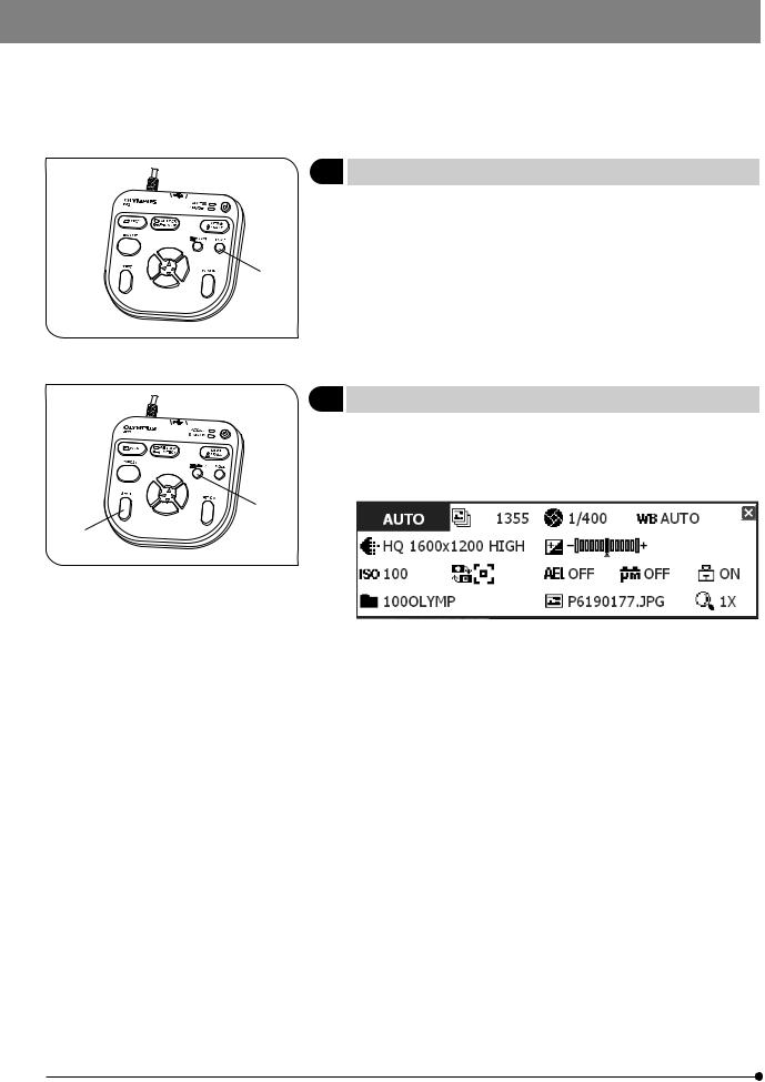
3 Selecting the Mode
The MODE button @ can be used to select the REC AUTO (auto-expo- sure recording), REC MANUAL (manual-exposure recording) or PLAY (playback) mode.
}When the DP21 is turned ON and the REC AUTO or REC MANUAL mode 1 is selected, the live image is displayed on the monitor screen.
}The default setting is REC AUTO. From the next time, the system is started up in the mode selected when it was turned OFF the last time.
Fig. 13
4 Viewing/Hiding the INFO Display
When the live image is displayed, the INFO display is displayed on the upper right of the screen as shown in the following example (which shows the display in REC AUTO mode). For details on the INFO display, see MENU/INFO display (p. 10).
2
1
Fig. 14
While holding the SHIFT button @, press the MENU button ² to view or hide the INFO display alternately.
}Even when the system is turned OFF with the INFO display hidden, it is displayed the next time the system is turned ON.
20

SAL System
1
2 3
5Viewing/Controlling the MENU Display
1.Press the MENU button @ to view or hide the MENU display alternately. For details on the MENU display items, see MENU display (p. 10). The MENU display is hidden with the default setting.
2.Press the cursor buttons ² to select an item and press the SET button ³ to enter the selection.
Fig. 15
Setting item icon |
|
Setting content list |
Setting item tabs
Basic operation flow of the MENU display
Viewing the MENU display:
Press the MENU button to view the MENU display.
Selecting a tab:
Press the cursor buttons 
 to select a setting item tab. After it, pressing --> enables selection of a setting item icon. Press
  to return to the beginning of tab selection step.
Selecting an icon:
Press the cursor buttons
 to select a setting item icon. After it, pressing --> enables selection in the setting content list. Press
  to return to the beginning of icon selection step.
Selecting a setting content
Press the cursor buttons
 to place the cursor on the desired setting content. When setting a pull-down item (resolution, etc.), press the cursor buttons
 after placing the cursor and select the desired item.
Entering the setting content:
Press the SET button to enter the selected setting content.
21

|
|
|
|
|
|
|
|
|
|
|
|
|
|
|
|
|
|
|
|
|
|
6 |
|
|
|
||||||||||||||||||
Setting the Live Resolution |
Default: 1600 x 1200 |
||||||||||||||||||||
|
|
|
|
|
|
|
|
|
|
|
|
|
|
|
|
|
|
|
With the DP21, the resolution of the live image can be selected from three |
||
|
|
|
|
|
|
|
|
|
|
|
|
|
|
|
|
|
|
|
options of UXGA:1600 x 1200, SVGA:800 x 600 and SVGA (binning) 800 x |
||
|
|
|
|
|
|
|
|
|
|
|
|
|
|
|
|
|
|
|
600. The characteristics of each resolution are as follows. |
||
|
|
|
|
|
|
|
|
|
|
|
|
|
|
|
|
|
|
|
|||
|
|
|
|
|
|
|
|
|
|
|
|
|
|
|
|
|
|
|
|
|
|
|
|
|
|
|
|
|
|
|
|
|
|
|
|
|
|
|
|
|
1600 x 1200 |
High-definition image observation/recording, which is |
|
|
|
|
|
|
|
|
|
|
|
|
|
|
|
|
|
|
|
|
|||
|
|
|
|
|
|
|
|
|
|
|
|
|
|
|
|
|
|
|
|
recommended when viewing clear image on a large |
|
|
|
|
|
|
|
|
|
|
|
|
|
|
|
|
|
|
|
|
|
||
|
|
|
|
|
|
|
|
|
|
|
|
|
Fig. 16 |
|
monitor screen. |
|
|||||
|
|
|
|
|
|
|
|
|
|
|
|
|
|
Frame rate: 15 fps |
|
||||||
|
|
|
|
|
|
|
|
|
|
|
|
|
|
|
|
|
|
|
|
|
|
|
|
|
|
|
|
|
|
|
|
|
|
|
|
|
|
|
|
|
|
|
|
|
|
|
|
|
|
|
|
|
|
|
|
|
|
|
|
|
|
|
800 x 600 |
Image observation at a high frame rate displays smooth |
|
|
|
|
|
|
|
|
|
|
|
|
|
|
|
|
|
|
|
|
|
live images even when the target moves during ex- |
|
|
|
|
|
|
|
|
|
|
|
|
|
|
|
|
|
|
|
|
|
amination, etc. |
|
|
|
|
|
|
|
|
|
|
|
|
|
|
|
|
|
|
|
|
|
Frame rate: 27 fps |
|
|
|
|
|
|
|
|
|
|
|
|
|
|
|
|
|
|
|
|
|
|
|
|
|
|
|
|
|
|
|
|
|
|
|
|
|
|
|
|
|
|
800x 600 |
Sensitivity is 4 times higher than other modes. Obser- |
|
|
|
|
|
|
|
|
|
|
|
|
|
|
|
|
|
|
|
|
(Binning) |
vation and recording of bright image are possible even |
|
|
|
|
|
|
|
|
|
|
|
|
|
|
|
|
|
|
|
|
|
the target is dark. |
|
|
|
|
|
|
|
|
|
|
|
|
|
|
|
|
|
|
|
|
|
Frame rate: 27 fps |
|
|
|
|
|
|
|
|
|
|
|
|
|
|
|
|
|
|
|
|
|
|
|
|
|
|
|
|
|
|
|
|
|
|
|
|
|
|
|
|
|
|
}If the set resolution differs from the resolution available with the monitor, |
||
|
|
|
|
|
|
|
|
|
|
|
|
|
|
|
|
|
|
|
the image is magnified or reduced according to the monitor screen size. |
||
|
|
|
|
|
|
|
|
|
|
|
|
|
|
|
|
|
|
|
When the image is magnified, the noise in it is also magnified and may |
||
|
|
|
|
|
|
|
|
|
|
|
|
|
|
|
|
|
|
|
become noticeable. |
|
|
|
|
|
|
|
|
|
|
|
|
|
|
|
|
|
|
|
|
|
}Live images are magnified according to the resolution of the monitor. |
||
|
|
|
|
|
|
|
|
|
|
|
|
|
|
|
|
|
|
|
However, the optimum aspect ratio may sometimes not be achieved. To |
||
|
|
|
|
|
|
|
|
|
|
|
|
|
|
|
|
|
|
|
display the images at the optimum aspect ratio, refer to “Monitor resolu- |
||
|
|
|
|
|
|
|
|
|
|
|
|
|
|
|
|
|
|
|
tion setting" on page 56. |
|
|
|
7 |
OTWB (One-Touch White Balance) |
|
|
|
|
Adjust the white balance before recording to record image in optimum |
|
|
|
color tones. |
|
1. |
Display an exclusively white live image. |
|
1 |
|
· During transmitted light observation, remove the specimen. |
|
|
|
· During reflected light observation, set a piece of white paper in place of |
|
|
|
|
the specimen. |
|
2. |
Press the OTWB button @ to adjust the white balance. |
|
|
3. |
When the white balance is set, message “White balance setting is com- |
|
Fig. 17
pleted.” is displayed on the monitor and disappears automatically in 3 seconds. This message can also be switched off by pressing any button other than the main switch.
}If the adjustment fails, message “white balance setting failed.” is displayed. As this message does not disappear automatically, press the SET/OK button to switch it off and retry the adjustment.
}The white balance adjustment fails when the live image is not completely white, the exposure is inappropriate (too bright or too dark), etc.
}The white balance can also be adjusted using AUTO WB and manual (by means of direct entry of color temperature) as well as OTWB (One-Touch White Balance), and the adjustment mode can be selected in the MENU display. For details, see Setting the white balance (WB) mode (p. 33).
22

SAL System
²8 Recording Still Images
1. On the microscope, frame the image to be recorded and focus on it.
1 |
Tip |
|
|
|
To facilitate focusing, use the zoom display of the live image (p. 27) or |
|
display the focusing indicator (p. 37). |
2. Press the EXPOSE button @ to record the still image, which is saved in the USB memory connected to the control box or hand switch.
}Switching the Rec View setting (p. 34) ON displayed the recorded image Fig. 18 temporarily during live image display. (With the default, the recorded im-
age is displayed for 5 second after recording.)
Tip
The image save destination can be changed (p. 31). The image can also be saved in the networked PC by advance setting.
3.The ACCESS LED lights during recording of the image. Message “Saving image” is also displayed on the center of the screen.
4.The INFO display shows the number of remaining image.
CAUTION When the number of remaining image reaches 0, warning message “MEMORY FULL” is displayed on the monitor screen.
 CAUTION
·Do not disconnect the USB memory while the ACCESS LED ² is lighting.
·As the data quantity varies depending on the recording target, more images than the number of remaining image may sometimes be recordable. Also, the counter may not decrement after recording or may not increment even when an image is erased.
·The number of remaining image varies depending on the capacity of the USB memory.
·The USB memory has its own service life. Its capacity may decrease depending on its conditions.
·It is not possible to record more than 10,000 images even when the USB memory has a remaining idle capacity.
·The folder and file names of the recorded images are created automatically. See page 33 for details.
23
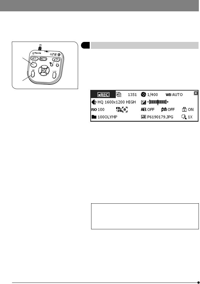
9 |
Recording Movies |
|
2 |
1. |
On the microscope, frame the image to be recorded and focus on it. |
2. |
While holding the SHIFT button @, press the EXPOSE button ² to start |
|
|
|
movie recording. |
|
3. |
To stop movie recording, press the EXPOSE button ². The movie is saved |
|
|
in the USB memory. |
|
}The INFO display shows the following information during movie record- |
|
1 |
|
ing (the MODE display shows “REC”). |
Fig. 19
}The image size and format of the recorded movie are as follows and cannot be modified.
Image size: 400 x 300 Format: Non-compressed AVI
}The settings cannot be changed in the middle of movie recording. They should be changed after completing the recording.
}A movie can be recorded for up to 5 minutes (this period is variable depending on the frame rate and storage medium capacity). Movie recording may stop anytime automatically when the maximum file size is reached or the storage medium runs out of capacity.
}“  ” on the INFO display indicates the number of recordable still-image images, and the number of recordable movies is not displayed.
}When the system is turned OFF in the middle of movie recording, the movie ends at that point.
}The folder and file names of the recorded movies are created automatically. See page 33 for details.
Tip
The movie save destination can be changed (p. 31).
However, the movie frame rate may drop depending on the data write speed of the recording medium (at the time of playback, such a movie look like a fast-forward movie).
24

SAL System
2-6 Recording Function Setting/Operation (REC)
2-6-1 Operation using the hand switch
This section describes the method of operating the basic functions using the hand switch. The hand switch has buttons to which the functions frequently used in microscope observation are assigned to facilitate the recording of clear images.
1 Available Functions
The hand switch of the DP21 incorporates the following functions. For details of each function, see the description in the applicable pages.
Fig. 20
Name |
Function |
Buttons |
Remark |
|||||
Exposure adjustment |
Modifies the exposure time set by AE |
|
|
|
|
|
|
|
(AUTO mode) |
(Auto Exposure). |
|
|
|
|
|
|
|
|
|
|
|
|
|
|
|
|
Exposure time setting |
Sets the exposure time by direct entry |
|
|
|
|
|
|
To enter the exposure time directly, |
(MANUAL mode) |
of the figure. |
|
|
|
|
|
|
press the MODE button to select the |
|
|
|
|
|
|
|
|
REC MANUAL mode. |
|
|
|
|
|
|
|
|
|
SPOT metering |
Switches the metering area between |
|
|
|
|
|
|
Select the metering area according to |
|
normal (30%) and SPOT (1%). |
|
|
|
|
|
|
the specimen. See p. 26 for details. |
|
|
|
|
|
|
|
|
|
AE lock |
Locks the exposure time set by AE |
|
|
|
|
|
|
|
|
(Auto Exposure). |
|
|
|
|
|
|
|
|
|
|
|
|
|
|
|
|
|
|
|
|
|
|
|
|
|
OTWB |
To reproduce optimum colors, image |
|
|
|
|
|
|
Set the entire live image white when |
|
a white object, measures the white |
|
|
|
|
|
|
executing OTWB. |
|
balance and stores the optimum white |
|
|
|
|
|
|
See p. 22 for details. |
|
balance for actual recording status in |
|
|
|
|
|
|
|
|
the DP21. |
|
|
|
|
|
|
|
|
|
|
|
|
|
|
|
|
Scrolling |
Scrolls the zoomed image. |
|
|
|
|
|
|
Scrolling of the image is also possible |
|
|
|
|
|
|
|
|
by holding the SET/OK button instead |
|
|
|
|
|
|
|
|
|
|
|
|
|
|
|
|
|
of the SHIFT button. |
|
|
|
|
|
|
|
|
|
25

1 2
Fig. 21
1
Fig. 22
26
2Exposure Adjustment
REC AUTO mode
The exposure time set by AE (Auto Exposure) can be corrected (by up to 2 EV in 1/3 EV steps).
When the specimen is dark, +EV correction will extend the exposure time and give an over-exposure type effect. When it is bright, the -EV correction will shorten the exposure time and give an under-exposure type effect.
Press the cursor button  @ or
@ or  ² to set the exposure adjustment value. The setting can be checked on the following scale at the bottom of the INFO display.
(Example) +4/3EV
-2EV 0 +2EV
}Switch off the MENU display before the exposure adjustment. If the MENU display is shown, press the MENU button on the hand switch to hide it.
3SPOT Metering Setting
REC AUTO mode
}When the observation target is dispersed in the image, the image may become too bright or too dark due to the effect of the background. In such a case, the problem may sometimes be improved by changing the metering area.
}The center average metering is set normally.
·Center average metering: Photometry of the 30% area on the image center.
·Spot metering: Photometry of the 1% area on the image center.
1.Press the SPOT button @ to switch the metering area between SPOT and Average.
The INFO display shows the current setting.
Center average metering (30%)
Spot metering (1%)
2.The metering area can be displayed or hidden by setting in the MENU display. When it is set to be hidden, it appears only when the SPOT button is pressed but disappears in 3 sec.
 Loading...