


PX-42VR5

NEC plasma display
External Control Manual
(for PX-42VR5/42XR3/50XR4/61XR3)
e.g., Personal computer
Application
These specifications are applicable to NEC plasma monitors and
communications control from external equipment.
"Please also support the command of VP series and refer to the manual of the
conventional model about specification."
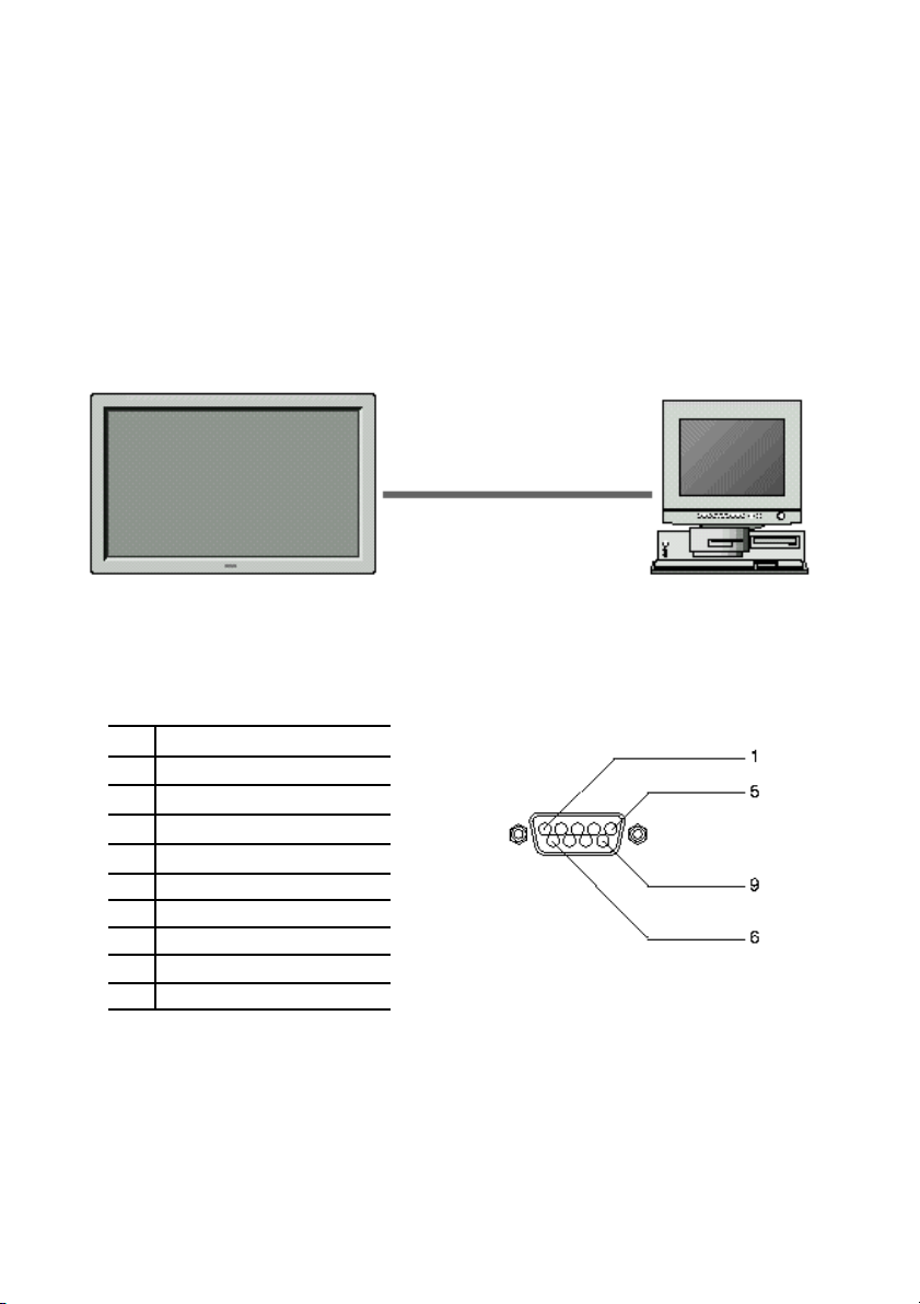
Connections
Connections should be made as described below.
1) Connector on the plasma monitor side: EXTERNAL CONTROL connector.
plasma monitor
Type of connector: D-Sub 9-pin male
No. Pin Name
1 No Connection
2 RXD (Receive data)
3 TXD (Transmit data)
4 DTR (DTE side ready)
5 GND
6 DSR (DCE side ready)
7 RTS (Ready to send)
8 CTS (Clear to send)
9 No Connection
External equipment
2

2) Connector on the external equipment side: Serial port (RS-232C) connector.
See the specifications of the equipment that is to be connected for the type of
connector and the pin assignment.
3) Wiring
Use a crossed (reverse) cable.
Wire the cable so that each pair of data lines cross between the two devices.
These data line pairs are RXD (Receive data) and TXD (Transmit data), DTR
(DTE side ready) and DSR (DCE side ready), and RTS (Ready to send) and CTS
(Clear to send).
Communication Parameters
(1) Communication system Asynchronous
(2) Interface RS-232C
(3) Baud rate 9600 bps
(4) Data length 8 bits
(5) Parity Odd
(6) Stop bit 1 bit
(7) Communication code Hex
3
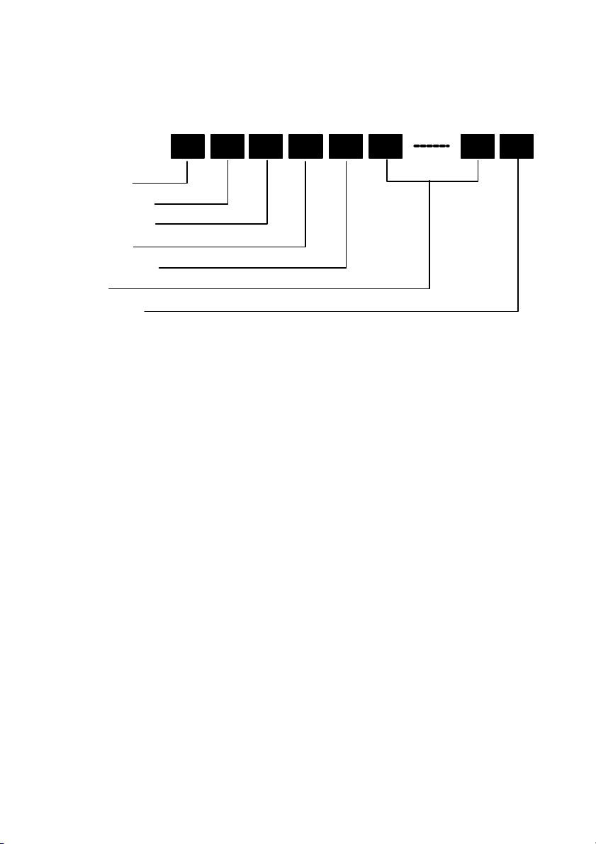
8bit 8bit 8bit 8bit 8bit 8bit 8bit 8bit
Communication Format
Command 1
Unit ID 1
Unit ID 2
Command 2
Data length
Data
Check sum
Command1
Command 1, along with command 2, is a number used to distinguish each
command.
When making it operate using ID, bit1 and bit0 are set up as follows.
Bit1,Bit0 Unit ID distinction bit
11B :Usually, a form (with no ID)
10B :Usually, a form (with no ID)
01B :Set ID
00B :Video wall ID
In the case of ACK, when the lower order 4 bits is FH (as in 3FH and
7FH), this indicates that the commands and data of the supported
equipment have been received. When the lower order 4 bits is BH (as in
3BH and 7BH), this indicates that unsupported commands and data
have been received.
Unit ID1,2 (UA1,UA2)
Unit ID 1 and unit ID 2 are numbers used to identify the equipment
that is to be connected.
60H is used for the plasma monitor and 80H is used for external control
equipment such as a personal computer.
4

1) Unit ID 1: Indicates the equipment sending the signal. When
supporting Set ID by the command 1, 4 bits of low ranks of Set ID are
set up.
2) Unit ID 2: Indicates the equipment receiving the signal. When
supporting Set ID by the command 1, 4 bits of higher ranks of Set ID
are set up.
* Set ID : it is the apparatus number assigned to each plasma monitor.
5
Total 208H
Command 2
Command 2, along with command 1, is a number used to distinguish each
command.
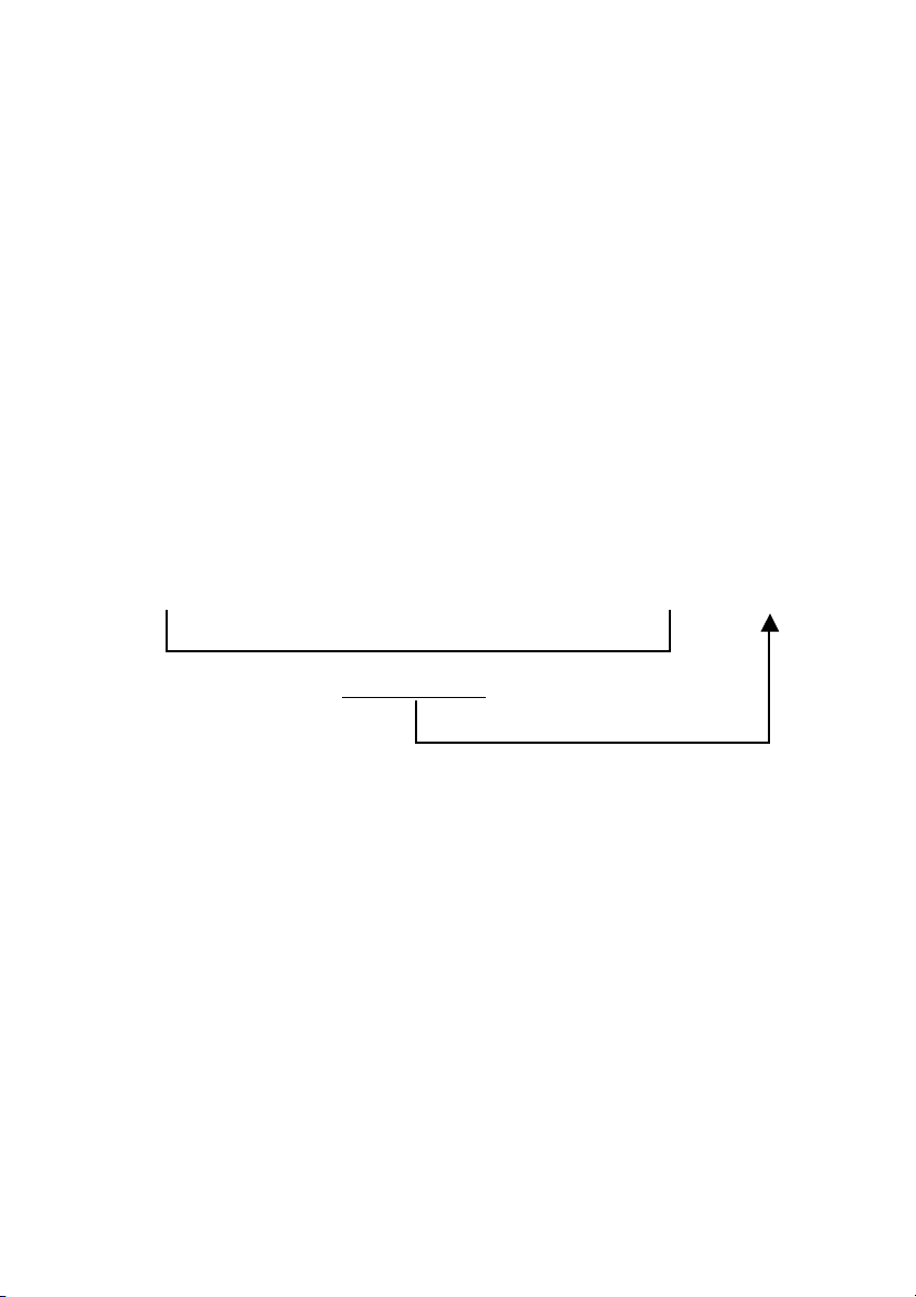
Check Sum (CKS), Error Processing, and ACK
1) The check sum described below and RS-232C odd parity are used together for
a check of the received data. The check sum is the lower order 8 bits of one
frame of sent or received data comprising the sum total of Command 1, Unit
ID 1 and 2, Command 2, Data Length, and Data.
Check Sum Example
DFH 80H 60H 47H 01H 01H 08H
Command1 Unit ID1 Unit ID2 Command2 Data Length Data Check Sum
2) Error Processing
• When the communication interval is vacant for more than 4 ms, thereafter a
received Command 1 will be recognized. If, at this time, meaningful data
cannot be recognized, that data will not be recognized (as valid data).
• An ACK will not be returned unless the receive data error, the check sum
error, and the receive data are all taken in.
6

The control method of the set by Set ID
When controlling two or more sets of plasma monitors, if the command
using Set ID is used, it will become controllable individually.
The example of the POWER ON command to the plasma monitor which set
ID as "5" is shown below.
It is not based on ID but is the POWER ON command to all sets.
9F 80 60 4E 00 CD
In ID= "5", the value of ID-1=4 is set up.
9D 84 60 4E 00 CF
The example of a change in the single mode of a 4th page multi-system configuration and
the multi-mode is shown below.
ID of the set used as a master(etc PC) is set to 50, and it assumes that ID is shaken by
AUTO ID to each set. ID shaken at each set is as follows.
Upper left set (master) ID = 50 = 32h
Upper right set ID = 51 = 33h
Lower right set ID = 52 = 34h
Lower left set ID = 53 = 35h
Transmission Data
DD 81 63 03 03 03 01 00 CB
DD 82 63 03 03 03 02 00 CD
DD 83 63 03 03 03 03 00 CF
DD 84 63 03 03 03 04 00 D1
Transmission of the above command performs a 4th page multi SPLIT display.
Moreover, the following commands are published in order to change a 4th page
multi-display into a single mode display.
DF 80 60 03 03 01 01 00 C7
All sets become a single mode display by the above-mentioned command.
Since this command does not specify Set ID, all sets execute it.
*:Control by ID may not be able to be performed depending on connection with
external control apparatus.
7

Command Reference List
CMD1 CMD2 LEN
01 Power ON 9FH 4EH 00H
02 Power OFF 9FH 4FH 00H
03 Input Switch Change DFH 47H 01H
04 VOLUME Gain Data DFH 7FH 03H
05 AUDIO Mute ON 9FH 3EH 00H
06 AUDIO Mute OFF 9FH 3FH 00H
07 CONTRAST Gain Data DFH 7FH 03H
08 BRIGHT Gain Data DFH 7FH 03H
09 SHARPNESS Gain Data DFH 7FH 03H
10 Color Gain Data DFH 7FH 03H
11 TINT Gain Data DFH 7FH 03H
12 PICTURE MODE Select DFH 0AH 01H
13 COLOR TEMP SELECT DFH 00H 01H
14 RED Gain Data DFH 7FH 04H
15 GREEN Gain Data DFH 7FH 04H
16 BLUE Gain Data DFH 7FH 04H
17 NR MODE Set DFH C0H 01H
18 BASS Gain Data DFH 7FH 03H
19 TREBLE Gain Data DFH 7FH 03H
20 BALANCE Gain Data DFH 7FH 03H
21 SCREEN MODE Select DFH 51H 01H
22 V.POSITION Gain Data DFH 7FH 03H
23 H.POSITION Gain Data DFH 7FH 03H
24 V-HEIGHT Gain Data DFH 7FH 03H
25 H-WIDTH Gain Data DFH 7FH 03H
26 AUTO PICTURE Select DFH 7FH 03H
27 PHASE Gain Data
(FINE PICTURE Set)
28 CLOCK Gain Data
(PICTURE ADJUST Set)
29 OSM ADJ. position Data DFH 1AH 02H
30 POWER MGT Select DFH 1AH 02H
31 GRAY LEVEL Set DFH C6H 01H
32 CINEMA MODE Set DFH C1H 01H
33 LONG LIFE Set
(PDP SAVER Set)
34 SCREEN WIPER Set DFH C8H 04H
35 ALL RESET 1FH 54H 00H
36 Audio Select Set DFH 70H 02H
37 BNC INPUT DFH 8CH 01H
38 RGB Select DFH 8BH 01H
39 HD Select DFH 8AH 01H
DFH 7FH 03H
DFH 7FH 03H
DFH 6BH 03H
8

40 LANGUAGE Select DFH 5BH 01H
41 COLOR SYSTEM Select DFH 5CH 01H
42 FREQUENCY Request 1FH 26H 00H
43 Input MODE Request 1FH 41H 00H
44 VIDEO ADJ Request 1FH 45H 00H
45 Audio Select Request 1FH 6FH 00H
46 Failure Mode Request 1FH 3FH 00H
47 MODEL NAME Request 1FH 17H 00H
48 D-SUB INPUT DFH 8DH 01H
49 LOW TONE DFH 0CH 01H
50 COLOR TUNE DFH 0DH 08H
51 GAMMA Gain Data DFH 13H 04H
52 Running Sense 1FH 88H 00H
53 OSM OBITER DFH 5FH 01H
54 Input Skip 5FH 61H 01H
55 SERIAL No. Request 1FH 15H 00H
56 S1/S2 SELECT DFH 89H 01H
57 SOFT FOCUS DFH 65H 01H
58 PLUG and PLAY DFH 8EH 01H
59 BLACK LEVEL
(DIGITAL SIGNAL LEVEL)
1
60*
MULTI(SPRIT) SCREEN
Select
1
61*
SUB.P DETECT DFH 7AH 01H
1
62*
ZOOM NAV DFH 7BH 01H
1
63*
PICTURE FREEZE DFH 7CH 01H
1
64*
PAUSE COMMAND DFH 7DH 01H
65 OSM CONTRAST DFH 37H 01H
2
66*
CLOSED CAPTION DFH 3CH 01H
2
67*
CAPTION CONTRAST DFH 3DH 01H
68 PICTURE MEMORY Select DFH 38H 01H
69 PICTURE MEMORY Set DFH 25H 02H
70 PICTURE MEMORY
NOTE WRITE
71 SET UP LEVEL DFH 35H 01H
72 BACK GROUND DFH 36H 01H
73 PDP SAVER AUTO select DFH 2CH 01H
*1:This function is only 50 or 61 inch model
*2:This function is only A version
DFH 8FH 01H
DFH 07H 01H
DFH 2DH 0CH
9

01. Power ON
Function
The external control equipment switches on the power of the plasma monitor.
Transmission Data
9FH 80H 60H 4EH 00H CKS
ACK
The plasma monitor returns the following ACK when the power is switched
on.
3FH 60H 80H 4EH 00H CKS
NOTE: Do not set the Power ON or Power OFF command continuously.
02. Power OFF
Function
The external control equipment switches off the power of the plasma monitor.
Transmission Data
9FH 80H 60H 4FH 00H CKS
ACK
The plasma monitor returns the following ACK when the power is switched
off.
3FH 60H 80H 4FH 00H CKS
NOTE: Do not set the Power ON or Power OFF command continuously.
10

03. Input Switch Change
Function
The external control equipment switches the input of the plasma monitor.
Transmission Data
DFH 80H 60H 47H 01H DATA00 CKS
DATA00 : Input Select 01H : Video1
02H : Video2
03H : Video3
05H : HD (HD1 or DTV or DTV1)
06H : HD2(DTV2 or SCART1/SCART2)
07H : RGB1 / PC1
08H : RGB2 / PC2
0CH : RGB3 / PC3
0EH : HD/DVD3
ACK
The plasma monitor returns the following ACK when the input is switched.
3FH 60H 80H 47H 00H CKS
11

04. VOLUME Gain Data
Function
The external control equipment changes the VOLUME gain data of the plasma
monitor.
Transmission Data
DFH 80H 60H 7FH 03H DATA00 DATA01 DATA02 CKS
DATA00: USER SOUND Gain Flag 05H
DATA01: VOLUME Gain Flag 01H
DATA02: VOLUME Gain 00H: Step0
:
0AH: Step10 (Default)
:
2AH: Step42
ACK
7FH 60H 80H 7FH 02H DATA00 DATA01 CKS
DATA00: USER SOUND Gain Flag 05H
DATA01: VOLUME Gain Flag 01H
05. AUDIO Mute ON
Function
The external control equipment switches on AUDIO Mute of the plasma
monitor.
Transmission Data
9FH 80H 60H 3EH 00H CKS
ACK
3FH 60H 80H 3EH 00H CKS
06. AUDIO Mute OFF
Function
The external control equipment switches off AUDIO Mute of the plasma
monitor.
Transmission Data
9FH 80H 60H 3FH 00H CKS
ACK
3FH 60H 80H 3FH 00H CKS
12

07. CONTRAST Gain Data
Function
The external control equipment changes the CONTRAST gain data of the
plasma c
Transmission Data
DFH 80H 60H 7FH 03H DATA00 DATA01 DATA02 CKS
DATA00 : USER PICTURE Gain Flag 01H
DATA01 : CONTRAST Gain Flag 07H
DATA02 : CONTRAST Gain CCH : -52
:
FFH : -01
00H : 0
01H : +01
:
14H : +20
ACK
7FH 60H 80H 7FH 02H DATA00 DATA01 CKS
DATA00: USER PICTURE Gain Flag 01H
DATA01: CONTRAST Gain Flag 07H
08. BRIGHT Gain Data
Function
The external control equipment changes the BRIGHT gain data of the plasma
monitor.
Transmission Data
DFH 80H 60H 7FH 03H DATA00 DATA01 DATA02 CKS
DATA00 : USER PICTURE Gain Flag 01H
DATA01 : BRIGHT Gain Flag 08H
DATA02 : BRIGHT Gain E0H : -32
:
FFH : -01
00H : 0
01H : +01
:
20H : +32
ACK
7FH 60H 80H 7FH 02H DATA00 DATA01 CKS
13

DATA00 : USER PICTURE Gain Flag 01H
DATA01 : BRIGHT Gain Flag 08H
09. SHARPNESS Gain Data
Function
The external control equipment changes the SHARPNESS gain data of the
plasma monitor.
Transmission Data
DFH 80H 60H 7FH 03H DATA00 DATA01 DATA02 CKS
DATA00 : USER PICTURE Gain Flag 01H
DATA01 : SHARPNESS Gain Flag 06H
DATA02 : SHARPNESS Gain F0H : -16
:
FFH : -01
00H : 0
01H : +01
:
10H : +16
Only when a RGB signal is connected
DATA02 : SHARPNESS Gain 01H : 1
02H : 2
03H : 3
04H : 4
ACK
7FH 60H 80H 7FH 02H DATA00 DATA01 CKS
DATA00 : USER PICTURE Gain Flag 01H
DATA01 : SHARPNESS Gain Flag 06H
14

10. COLOR Gain Data
Function
The external control equipment changes the COLOR gain data of the plasma
monitor.
Transmission Data
DFH 80H 60H 7FH 03H DATA00 DATA01 DATA02 CKS
DATA00 : USER PICTURE Gain Flag 01H
DATA01 : COLOR Gain Flag 04H
DATA02 : COLOR Gain E0H : -32
:
FFH : -01
00H : 0
01H : +01
:
20H : +32
* COLOR Gain is from -22 (EAH) to +22 (16H) only during video.
ACK
7FH 60H 80H 7FH 02H DATA00 DATA01 CKS
DATA00 : USER PICTURE Gain Flag 01H
DATA01 : COLOR Gain Flag 04H
11. TINT Gain Data
Function
The external control equipment changes the TINT gain data of the plasma
monitor.
Transmission Data
DFH 80H 60H 7FH 03H DATA00 DATA01 DATA02 CKS
DATA00 : USER PICTURE Gain Flag 01H
DATA01 : TINT Gain Flag 05H
DATA02 : TINT Gain E0H: -32
:
* TINT Gain is from -22 (EAH) to FFH : -01
+22 (16H) only during video. 00H : 0
01H : +01
:
20H : +32
15

ACK
7FH 60H 80H 7FH 02H DATA00 DATA01 CKS
DATA00 : USER PICTURE Gain Flag 01H
DATA01 : TINT Gain Flag 05H
12. PICTURE MODE Select
Function
The external control equipment sets the picture mode of the plasma monitor.
Transmission Data
DFH 80H 60H 0AH 01H DATA00 CKS
DATA00: 01H : NORMAL
02H : THEATER1(It cannot choose in the still picture input of a
personal computer.)
03H : THEATER2(It cannot choose in the still picture input of a
personal computer.)
04H : Default
05H : Bright
ACK
7FH 60H 80H 0AH 01H DATA00 CKS
DATA00: 01H : NORMAL
02H : THEATER1
03H : THEATER2
04H : Default
05H : Bright
13. COLOR TEMP SELECT
Function
The external control equipment changes the COLOR TEMP of the plasma
monitor.
Transmission Data
DFH 80H 60H 00H 01H DATA00 CKS
DATA00 : 00H: low
01H: middle
02H: high
03H: middle low
16

ACK
7FH 60H 80H 00H 01H DATA00 CKS
DATA00 : 00H: low
01H: middle
02H: high
03H: middle low
14. RED Gain Data
Function
The external control equipment changes the RED Gain Data of the plasma
monitor.
Transmission Data
DFH 80H 60H 7FH 04H DATA00 to DATA03 CKS
DATA00 : USER PICTURE Gain Flag 01H
DATA01 : RED Gain Flag 01H
DATA02 : RED Gain1(Bias) D8H : -40
:
FFH : -01
00H : 0
01H : +01
:
1EH : +30
DATA03: RED Gain2(Drive) D8H : -40
:
FFH : -01
00H : 0
01H : +01
:
1EH : +30
ACK
7FH 60H 80H 7FH 02H DATA00 DATA01 CKS
DATA00 : USER PICTURE Gain Flag 01H
DATA01 : RED Gain Flag 01H
17

15. GREEN Gain Data
Function
The external control equipment changes the GREEN Gain Data of the plasma
monitor.
Transmission Data
DFH 80H 60H 7FH 04H DATA00 to DATA03 CKS
DATA00 : USER PICTURE Gain Flag 01H
DATA01 : GREEN Gain Flag 02H
DATA02 : GREEN Gain1(Bias) D8H : -40
:
FFH : -01
00H : 0
01H : +01
:
1EH : +30
DATA03: GREEN Gain2(Drive) D8H : -40
:
FFH : -01
00H : 0
01H : +01
:
1EH : +30
ACK
7FH 60H 80H 7FH 02H DATA00 DATA01 CKS
DATA00: USER PICTURE Gain Flag 01H
DATA01: GREEN Gain Flag 02H
18
 Loading...