


NEC PX1004UL-WH, PX1004UL-W-18, PX1004UL-BK, PX1004UL-B-18 User Manual
Projector
PX1004UL-WH/PX1004UL-BK
User’s Manual
Please visit our web site for User’s Manual in the latest version.
http://www.nec-display.com/dl/en/pj_manual/lineup.html
Model No.
NP-PX1004UL-WH/NP-PX1004UL-BK

Ver. 1 9/16
•Apple, Mac, Mac OS, and MacBook are trademarks of Apple Inc. registered in the U.S. and other countries.
•Microsoft, Windows, Windows Vista, Internet Explorer, .NET Framework and PowerPoint are either a registered trademark or trademark of Microsoft Corporation in the United States and/or other countries.
•MicroSaver is a registered trademark of Kensington Computer Products Group, a division of ACCO Brands.
•AccuBlend, NaViSet, and Virtual Remote are trademarks or registered trademarks of NEC Dispolay Solutions, Ltd. in Japan, in the United State and other countries.
•The terms HDMI and HDMI Hight-Definition Multimedia Interface, and the HDMI Logo are trademarks or registered trademarks of HDMI Licensing LLC in the United States and other countries.
•DisplayPort and DisplayPort Compliance Logo are trademarks owned by the Video Electronics Standards Association.
•HDBaseT™ is a trademark of HDBaseT Alliance.
•DLP and BrilliantColor are trademarks of Texas Instruments.
•Trademark PJLink is a trademark applied for trademark rights in Japan, the United States of America and other countries and areas.
•Wi-Fi®, Wi-Fi Alliance®, and Wi-Fi Protected Access (WPA, WPA2)® are registered trademarks of the Wi-Fi Alliance.
•Blu-ray is a trademark of Blu-ray Disc Association
•CRESTRON and ROOMVIEW are registered trademarks of Crestron Electronics, Inc.in the United States and other countries.
•Ethernet is either a registered trademark or trademark of Fuji Xerox Co., Ltd.
•Extron and XTP are registered trademarks of RGB Systems, Inc. in the United States.
•Other product and company names mentioned in this user’s manual may be the trademarks or registered trademarks of their respective holders.
•Virtual Remote Tool uses WinI2C/DDC library, © Nicomsoft Ltd.
•TOPPERS Software Licenses
The product includes software licensed under TOPPERS License.
For more information on each software, see “readme.pdf” inside the “about TOPPERS” folder on the supplied CDROM.
NOTES
(1)The contents of this user’s manual may not be reprinted in part or whole without permission.
(2)The contents of this user’s manual are subject to change without notice.
(3)Great care has been taken in the preparation of this user’s manual; however, should you notice any questionable points, errors or omissions, please contact us.
(4)Notwithstanding article (3), NEC will not be responsible for any claims on loss of profit or other matters deemed to result from using the Projector.
Important Information
Safety Cautions
Precautions
Please read this manual carefully before using your NEC projector and keep the manual handy for future reference.
CAUTION
To turn off main power, be sure to remove the plug from power outlet.
The power outlet socket should be installed as near to the equipment as possible, and should be easily accessible.
CAUTION
TO PREVENT SHOCK, DO NOT OPEN THE CABINET.
THERE ARE HIGH-VOLTAGE COMPONENTS INSIDE.
REFER SERVICING TO QUALIFIED SERVICE PERSONNEL.
This symbol warns the user that uninsulated voltage within the unit may be sufficient to cause electrical shock. Therefore, it is dangerous to make any kind of contact with any part inside of the unit.
This symbol alerts the user that important information concerning the operation and maintenance of this unit has been provided.
The information should be read carefully to avoid problems.
WARNING: TO PREVENT FIRE OR SHOCK, DO NOT EXPOSE THIS UNIT TO RAIN OR MOISTURE.
DO NOT USE THIS UNIT’S PLUG WITH AN EXTENSION CORD OR IN AN OUTLET UNLESS ALL THE PRONGS CAN BE FULLY INSERTED.
DOC Compliance Notice (for Canada only)
This Class A digital apparatus complies with Canadian ICES-003.
Machine Noise Information Regulation - 3. GPSGV,
The highest sound pressure level is less than 70 dB (A) in accordance with EN ISO 7779.
Disposing of your used product
In the European Union
EU-wide legislation as implemented in each Member State requires that used electrical and electronic products carrying the mark (left) must be disposed of separately from normal household waste. This includes projectors and their electrical accessories. When you dispose of such products, please follow the guidance of your local authority and/or ask the shop where you purchased the product.
After collecting the used products, they are reused and recycled in a proper way. This effort will help us reduce the wastes as well as the negative impact to the human health and the environment at the minimum level. The mark on the electrical and electronic products only applies to the current European Union Member States.
Outside the European Union
If you wish to dispose of used electrical and electronic products outside the European union, please contact your local authority and ask for the correct method of disposal.
For EU: The crossed-out wheeled bin implies that used batteries should not be put to the general household waste! There is a separate collection system for used batteries, to allow proper treatment and recycling in
accordance with legislation.
According the EU directive 2006/66/EC, the battery can’t be disposed improperly. The battery shall be separated to collect by local service.
i

Important Information
WARNING TO CALIFORNIA RESIDENTS:
Handling the cables supplied with this product will expose you to lead, a chemical known to the State of California to cause birth defects or other reproductive harm. WASH HANDS AFTER HANDLING.
RF Interference
WARNING
This is a Class A product. In a domestic environment this product may cause radio interference in which case the user may be required to take adequate measures.
CAUTION
•In order to reduce any interference with radio and television reception use a signal cable with ferrite core attached. Use of signal cables without a ferrite core attached may cause interference with radio and television reception.
•This equipment has been tested and found to comply with the limits for a Class A digital device, pursuant to Part 15 of the FCC Rules. These limits are designed to provide reasonable protection against harmful interference when the equipment is operated in a commercial environment. This equipment generates, uses, and can radiate radio frequency energy and, if not installed and used in accordance with the installation manual, may cause harmful interference to radio communications. Operation of this equipment in a residential area is likely to cause harmful interference in which case the user will be required to correct the interference at his own expense.
For UK only: In UK, a BS approved power cord with moulded plug has a Black (16 Amps) fuse installed for use with this equipment. If a power cord is not supplied with this equipment please contact your supplier.
Important Safeguards
These safety instructions are to ensure the long life of your projector and to prevent fire and shock. Please read them carefully and heed all warnings.
WARNING
• When the projector is damaged, cooling fluids may come out of internal part.
Should this happen, immediately turn off the AC supply to the projector and contact your dealer.
DO NOT touch and drink the cooling fluid. When the cooling fluids are swallowed or contacted with your eyes, please consult medical attention immediately. If you touch the cooling fluid with your hand, rinse your hands well under running water.
 Installation
•Do not place the projector in the following conditions:
-on an unstable cart, stand, or table.
-near water, baths, or damp rooms.
-in direct sunlight, near heaters, or heat radiating appliances.
-in a dusty, smoky or steamy environment.
-on a sheet of paper or cloth, rugs or carpets.
•Do not install and store the projector in the below circumstances. Failure to do so may cause of malfunction.
-In powerful magnetic fields
-In corrosive gas environment
-Outdoors
•If you wish to have the projector installed on the ceiling:
-Do not attempt to install the projector yourself.
-The projector must be installed by qualified technicians in order to ensure proper operation and reduce the risk of bodily injury.
-In addition, the ceiling must be strong enough to support the projector and the installation must be in accordance with any local building codes.
-Please consult your dealer for more information.
ii
Important Information
WARNING
•Do not cover the lens with the lens cap or equivalent while the projector is on. Doing so can lead to melting of the cap due to the heat emitted from the light output.
•Do not place any objects, which are easily affected by heat, in front of the projector lens. Doing so could lead to the object melting from the heat that is emitted from the light output.
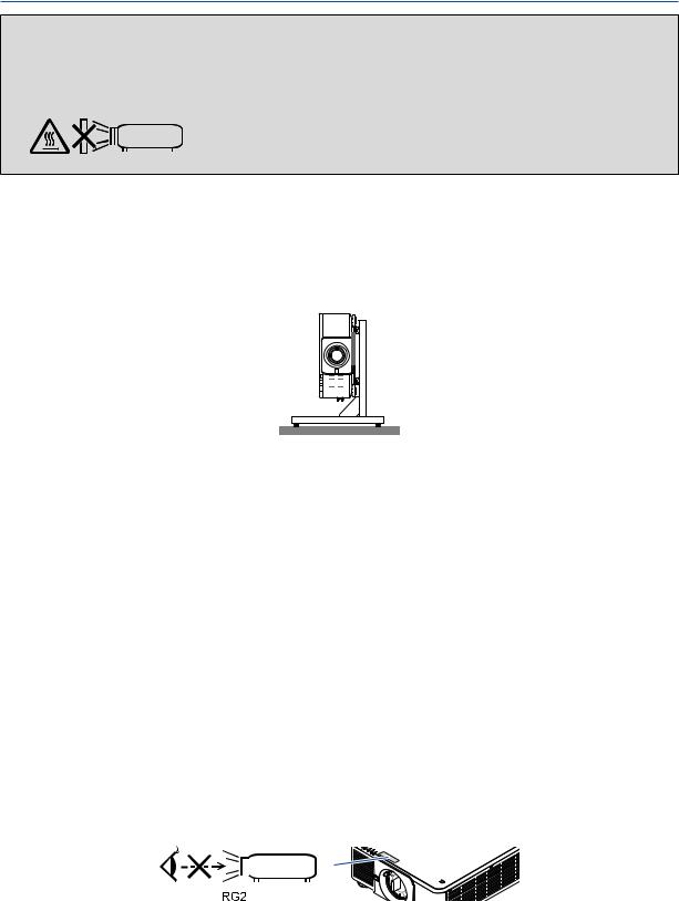
This projector can be installed any angle within vertical and horizontal 360° range, however, life of optical parts will be shorten in the following installation state:
•When the projector is installed on which lens faces downward.
•When the intake vent on the projector side faces downward in the portrait installation. (→ page 155)
For portrait installation, install the projector with the intake vent at the bottom. Observe precautions for portrait installation.
*A customized stand is required to be attached to the projector. (→ page 156)
 Fire and Shock Precautions
•Ensure that there is sufficient ventilation and that vents are unobstructed to prevent the build-up of heat inside your projector. Allow enough space between your projector and a wall. (→ page xi)
•Do not try to touch the exhaust vent on the rear side (when seen from the front) as it can become heated while the projector is turned on and immediately after the projector is turned off. Parts of the projector may become temporarily heated if the projector is turned off with the POWER button or if the AC power supply is disconnected during normal projector operation.
Use caution when picking up the projector.
•Prevent foreign objects such as paper clips and bits of paper from falling into your projector. Do not attempt to retrieve any objects that might fall into your projector. Do not insert any metal objects such as a wire or screwdriver into your projector. If something should fall into your projector, disconnect it immediately and have the object removed by a qualified service personnel.
•Do not place any objects on top of the projector.
•Do not touch the power plug during a thunderstorm. Doing so can cause electrical shock or fire.
•The projector is designed to operate on a power supply of 110-240V AC 50/60 Hz. Ensure that your power supply fits this requirement before attempting to use your projector.
•Do not look into the lens while the projector is on. Serious damage to your eyes could result.
•Do not look into the light source using optical instruments (such as magnifying glasses and mirrors). Visual impairment could result.
•When turning on the projector, ensure that nobody is facing towards the lens in the path of the light emitted from the laser. The following label, that is indicated at the lens-mounting-section on the projector cabinet, describes this projector is categorized in the risk group 2 of IEC62471-5: 2015. As with any bright light source, do not stare into the beam, RG2 IEC 62471-5: 2015.
• Keep any items (magnifying glass etc.) out of the light path of the projector. The light path being projected from the
iii

Important Information
lens is extensive, therefore any kind of abnormal objects that can redirect light coming out of the lens, can cause an unpredictable outcome such as a fire or injury to the eyes.
•Do not place any objects, which are easily affected by heat, in front of a projector exhaust vent.
Doing so could lead to the object melting or getting your hands burned from the heat that is emitted from the exhaust vent.
•Handle the power cord carefully. A damaged or frayed power cord can cause electric shock or fire.
-Do not use any power cord other than the one supplied with the projector.
-Do not bend or tug the power cord excessively.
-Do not place the power cord under the projector, or any heavy object.
-Do not cover the power cord with other soft materials such as rugs.
-Do not heat the power cord.
-Do not handle the power plug with wet hands.
•Turn off the projector, unplug the power cord and have the projector serviced by a qualified service personnel under the following conditions:
-When the power cord or plug is damaged or frayed.
-If liquid has been spilled into the projector, or if it has been exposed to rain or water.
-If the projector does not operate normally when you follow the instructions described in this user’s manual.
-If the projector has been dropped or the cabinet has been damaged.
-If the projector exhibits a distinct change in performance, indicating a need for service.
•Disconnect the power cord and any other cables before carrying the projector.
•Turn off the projector and unplug the power cord before cleaning the cabinet.
•Turn off the projector and unplug the power cord if the projector is not to be used for an extended period of time.
•When using a LAN cable:
For safety, do not connect to the terminal for peripheral device wiring that might have excessive voltage.
•Do not use the malfunctioned projector. It may cause of not only electric shock or fire but also serious damage to your eye sight.
•Do not let children to operate the projector by themselves. If the projector is operated by children, adults need to attend and keep their eyes on children.
•If damage or malfunction of the projector is found, immediately stop to use it and consult your dealer for repair.
•Never disassemble, repair, and remodel by end users. If these are performed by end users, it may cause of serious problem on users’ safety.
•Consult your dealer for disposing the projector. Never disassemble the projector before disposing it.
 CAUTION
•Keep hands away from the lens mounting portion while performing a lens shift. Failure to do so could result in fingers being pinched by the moving lens.
•Do not use the tilt-foot for purposes other than originally intended. Misuses such as gripping the tilt-foot or hanging on the wall can cause damage to the projector.
•Select [HIGH] in Fan mode if you continue to use the projector for consecutive days. (From the menu, select [SETUP] → [INSTALLATION(1)] → [FAN MODE] → [HIGH].)
•Do not unplug the power cord from the wall outlet or projector when the projector is powered on. Doing so can cause damage to the AC IN terminal of the projector and (or) the prong plug of the power cord.
To turn off the AC power supply when the projector is powered on, use the projector’s main power switch, a power strip equipped with a switch, or a breaker.
•When moving the projector, make sure you have at least two people. Attempting to move the projector alone could result in back pain or other injuries.
Caution on Handling the Optional Lens
When shipping the projector with the lens, remove the lens before shipping the projector. Always attach the dust cap to the lens whenever it is not mounted on the projector. The lens and the lens shift mechanism may encounter damage caused by improper handling during transportation.
Do not hold the lens part when carrying the projector.
Doing so could cause the focus ring to rotate, resulting in accidental dropping of the projector.
For mounting, replacing, and cleaning the lens, make sure to power off the projector and disconnect the power cord. Failure to do so can result in eye injury, electric shock, or burn injuries.
iv

Important Information
Precautions when installing or replacing the lens unit sold separately (LENS CALIBRATION)
After installing or replacing the lens unit, press either the SHUTTER/CALIBRATION button on the main unit or the INFO/L-CALIB. button while pressing the CTL button on the remote control to carry out [LENS CALIBRATION]. (→ page 18, 120)
By carrying out [LENS CALIBRATION], the adjustment range of the zoom, focus, and shift of the [LENS MEMORY] is calibrated.
Contact your dealer to install and replace the lens unit.
Remote Control Precautions
•Handle the remote control carefully.
•If the remote control gets wet, wipe it dry immediately.
•Avoid excessive heat and humidity.
•Do not short, heat, or take apart batteries.
•Do not throw batteries into fire.
•If you will not be using the remote control for a long time, remove the batteries.
•Ensure that you have the batteries’ polarity (+/−) aligned correctly.
•Do not use new and old batteries together, or use different types of batteries together.
•Dispose of used batteries according to your local regulations.
Light Module
1.A light module containing multiple laser diodes is equipped in the product as the light source.
2.These laser diodes are sealed in the light module. No maintenance or service is required for the performance of the light module.
3.End user is not allowed to replace the light module.
4.Contact qualified distributor for light module replacement and further information.
Laser Safety Caution
•This product is classified as RG2 of IEC62471-5 Edition 1.0 2015-06.
This product is classified as Class 3R of IEC 60825-1 Second edition 2007-03 and Class 1 of IEC60825-1 Third edition 2014-05.
Also complies with FDA performance standards 21 CFR 1040.10 and 1040.11 for laser products except for deviations pursuant to Laser Notice No.50, dated June 24, 2007.
Obey the laws and regulations of your country in relation to the installation and management of the device.
•Wave length 450–460 nm.
•Maximum power: 360 W
•The laser module is equipped in this product. Use of controls or adjustments of procedures other than those specified herein may result in hazardous radiation exposure.
 CAUTION
•Use of controls or adjustments or performance of procedures other than those specified herein may result in hazardous radiation exposure.
 CAUTION – CLASS 3R OF IEC 60825-1 SECOND EDITION LASER PRODUCT
LASER LIGHT – AVOID DIRECT EYE EXPOSURE
v
Important Information
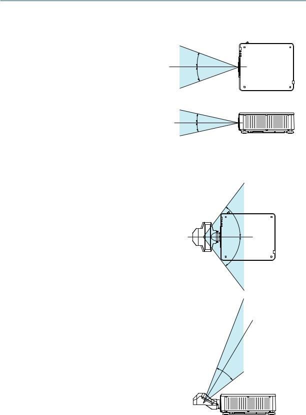
Applicable lens unit: NP16FL/NP17ZL/NP18ZL/NP19ZL/NP20ZL/NP21ZL/NP31ZL
Horizontal angle H
Lens |
Zoom |
|
|
|
|
Tele |
|
Wide |
|
NP16FL |
— |
|
32.9 |
|
NP17ZL |
15.5 |
|
21.7 |
|
NP18ZL |
12.4 |
|
16.1 |
H |
NP19ZL |
7.7 |
|
12.7 |
|
|
|
|||
NP20ZL |
5.3 |
|
7.9 |
H |
NP21ZL |
3.4 |
|
5.4 |
|
|
|
|||
NP31ZL |
27.8 |
|
33.6 |
|
Vertical angle V
Lens |
Zoom |
|
|
|
|
Tele |
|
Wide |
|
NP16FL |
— |
|
22.0 |
V |
NP17ZL |
9.8 |
|
14.0 |
|
|
V |
|||
NP18ZL |
7.8 |
|
10.2 |
|
NP19ZL |
4.8 |
|
8.0 |
|
NP20ZL |
3.3 |
|
5.0 |
|
NP21ZL |
2.1 |
|
3.4 |
|
NP31ZL |
18.2 |
|
22.5 |
|
Applicable lens unit: NP39ML
Horizontal angle H
Lens |
|
Zoom |
|
|
Tele |
|
Wide |
NP39ML |
— |
|
52.8 |
Vertical angle V
Lens |
|
Zoom |
|
|
|
Tele |
Wide |
|
|
|
|
V1 |
|
V2 |
NP39ML |
— |
9.68 |
|
21.52 |
V1
 V2
V2
H
H
vi
Important Information
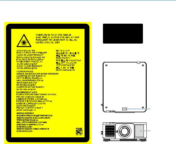
•The caution and the explanatory labels of the LASER PRODUCT in CLASS 3R conforming to IEC60825-1 Second edition, and in Class 1 conforming to IEC60825-1 Third edition are stuck on the below indicated positions.
Label 1 |
|
|
|
|
|
|
Label 2 |
||||||
|
|
|
|
|
|
|
|
|
|
|
|
|
|
|
|
|
|
|
|
|
|
|
|
|
|
|
|
|
|
|
|
|
|
|
|
|
|
|
|
|
|
|
|
|
|
|
|
|
|
|
|
|
|
|
|
|
|
|
|
|
|
|
|
|
|
|
|
|
|
|
|
|
|
|
|
|
|
|
|
|
|
|
|
|
|
|
|
|
|
|
|
|
|
|
|
|
|
|
|
|
|
|
|
|
|
|
|
|
|
|
|
|
|
|
|
|
|
|
|
|
|
|
|
|
|
|
|
|
|
|
|
|
|
|
|
|
|
|
|
|
|
|
|
|
|
|
|
|
|
|
|
|
|
|
|
|
|
|
|
|
|
|
|
|
|
|
|
|
|
|
|
|
|
|
|
|
|
|
|
|
|
|
|
|
|
|
|
|
|
|
|
|
|
|
|
|
|
|
|
|
|
|
|
|
|
|
|
|
|
|
|
|
|
|
|
|
|
|
|
|
|
|
|
|
|
|
|
|
|
|
|
|
|
|
|
|
|
|
|
|
|
|
|
|
|
|
|
|
|
|
|
Label 2
Label 1
vii

Important Information
•Manufacturer's ID Label (For PX1004UL-WH)
(For PX1004UL-BK)
Position of the Manufacturer's ID Label
viii
Important Information
About Copyright of original projected pictures:
Please note that using this projector for the purpose of commercial gain or the attraction of public attention in a venue such as a coffee shop or hotel and employing compression or expansion of the screen image with the following functions may raise concern about the infringement of copyrights which are protected by copyright law:
[ASPECT RATIO], [KEYSTONE], Magnifying feature and other similar features.
Turkish RoHS information relevant for Turkish market
EEE Yönetmeliğine Uygundur.
ix

Important Information
 Health precautions to users viewing 3D images
Before viewing, be sure to read health care precautions that may be found in the user’s manual included with your 3D eyeglasses or your 3D compatible content such as Blu-ray Discs, video games, computer’s video files and the like. To avoid any adverse symptoms, heed the following:
•Do not use 3D eyeglasses for viewing any material other than 3D images.
•Allow a distance of 2 m/7 feet or greater between the screen and a user. Viewing 3D images from too close a distance can strain your eyes.
•Avoid viewing 3D images for a prolonged period of time. Take a break of 15 minutes or longer after every hour of viewing.
•If you or any member of your family has a history of light-sensitive seizures, consult a doctor before viewing 3D images.
•While viewing 3D images, if you get sick such as nausea, dizziness, queasiness, headache, eyestrain, blurry vision, convulsions, and numbness, stop viewing them. If symptoms still persist, consult a doctor.
•View 3D images from the front of the screen. Viewing from an angle may cause fatigue or eyestrain.
Power management function
In order to keep power consumption low, the following power management functions (1) and (2) have been set when shipped from the factory. Please display the on-screen menu and change the settings (1) and (2) according to the aim of using the projector.
1.STANDBY MODE (Factory preset: NORMAL)
•When [NORMAL] is selected for [STANDBY MODE],the following terminals and functions will not work: HDMI OUT terminal,Ethernet/HDBaseT Port,USB Port,LAN functions,Mail Alert function
(→ page 136)
2.AUTO POWER OFF (Factory preset: 1 hour)
•When [1:00] is selected for [AUTO POWER OFF],you can enable the projector to automatically turn off in 1 hour if there is no signal received by any input or if no operation is performed.
(→ page 137)
x
Important Information
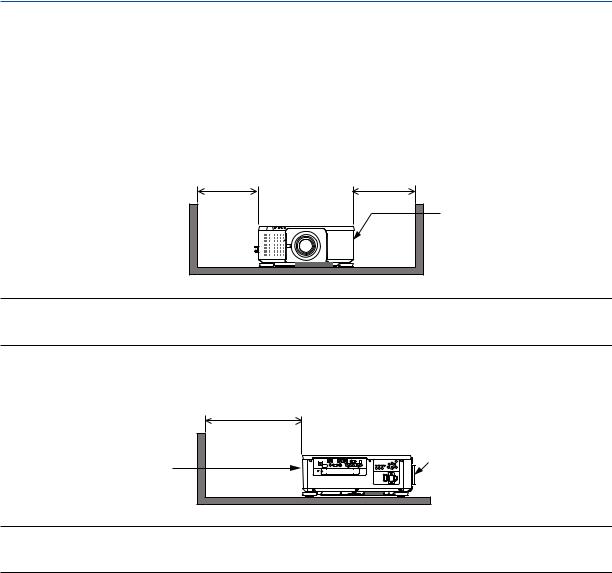
Clearance for Installing the Projector
Allow ample clearance between the projector and its surroundings as shown below.
The high temperature exhaust coming out of the device may be sucked into the device again.
Avoid installing the projector in a place where air movement from the HVAC is directed at the projector.
Heated air from the HVAC can be taken in by the projector’s intake vent. If this happens, the temperature inside the projector will rise too high causing the over-temperature protector to automatically turn off the projectors power.
• Concerning to the portrait projection, please refer “Portrait projection” on page 155.
Example 1 – If there are walls on both sides of the projector.
30 cm/11.8" or greater |
30 cm/11.8" or greater |
Intake vent
NOTE:
The drawing shows the proper clearance required for the left and right of the projector assuming sufficient clearance has been kept for the front, back and top of the projector.
Example 2 – If there is a wall behind the projector.
50 cm/19.7" or greater
Lens
Exhaust vent
NOTE:
The drawing shows the proper clearance required for the back of the projector assuming sufficient clearance has been kept for the right, left and top of the projector.
xi

Table of Contents |
|
Important Information............................................................................................ |
i |
1. Introduction........................................................................................................... |
1 |
What’s in the Box?.......................................................................................................... |
1 |
Introduction to the Projector............................................................................................ |
3 |
General...................................................................................................................... |
3 |
Light source · Brightness........................................................................................... |
3 |
Installation................................................................................................................. |
3 |
Videos........................................................................................................................ |
3 |
Network..................................................................................................................... |
4 |
Energy-saving............................................................................................................ |
4 |
About this user’s manual........................................................................................... |
5 |
Part Names of the Projector............................................................................................ |
6 |
Front/Top................................................................................................................... |
6 |
Rear........................................................................................................................... |
7 |
Controls/Indicator Panel............................................................................................ |
8 |
Terminals Features.................................................................................................... |
9 |
Part Names of the Remote Control............................................................................... |
10 |
Battery Installation................................................................................................... |
11 |
Remote Control Precautions................................................................................... |
11 |
Operating Range for Wireless Remote Control....................................................... |
12 |
Using the Remote Control in Wired Operation........................................................ |
12 |
2. Projecting an Image (Basic Operation)................................................ |
13 |
Flow of Projecting an Image.......................................................................................... |
13 |
Connecting Your Computer/Connecting the Power Cord............................................. |
14 |
Using the Supplied Power Cords............................................................................. |
15 |
Using the Power Cord Stopper................................................................................ |
16 |
Turning on the Projector................................................................................................ |
17 |
Performing Lens Calibration ................................................................................... |
18 |
Note on Startup screen (Menu Language Select screen)....................................... |
19 |
Selecting a Source........................................................................................................ |
20 |
Selecting the computer or video source.................................................................. |
20 |
Adjusting the Picture Size and Position........................................................................ |
22 |
Adjusting the vertical position of a projected image (Lens shift).............................. |
23 |
Focus....................................................................................................................... |
26 |
Zoom....................................................................................................................... |
31 |
Adjusting the Tilt Foot.............................................................................................. |
32 |
Optimizing Computer Signal Automatically................................................................... |
33 |
Adjusting the Image Using Auto Adjust................................................................... |
33 |
Turning off the Projector................................................................................................ |
34 |
After Use....................................................................................................................... |
35 |
3. Convenient Features...................................................................................... |
36 |
Turn off the light of the projector (LENS SHUTTER).................................................... |
36 |
Turning off the Image (AV-MUTE)................................................................................ |
36 |
Turning Off the On-Screen Menu (On-Screen Mute).................................................... |
36 |
Shift the On-Screen Menu displaying position.............................................................. |
37 |
xii

Table of Contents |
|
Freezing a Picture......................................................................................................... |
37 |
Magnifying a Picture...................................................................................................... |
38 |
Changing LIGHT MODE/Checking Energy-Saving Effect Using LIGHT MODE |
|
[LIGHT MODE]........................................................................................................ |
39 |
Checking Energy-Saving Effect [CARBON METER]............................................... |
41 |
Correcting Horizontal and Vertical Keystone Distortion [CORNERSTONE]................. |
42 |
Preventing the Unauthorized Use of the Projector [SECURITY]................................... |
45 |
Projecting 3D videos..................................................................................................... |
48 |
Procedure to watch 3D videos using this projector................................................. |
48 |
When videos cannot be viewed in 3D..................................................................... |
51 |
Controlling the Projector by Using an HTTP Browser................................................... |
52 |
Storing Changes for Lens Shift, Zoom, and Focus [LENS MEMORY].......................... |
60 |
To store your adjusted values in [REF. LENS MEMORY]:...................................... |
61 |
To call up your adjusted values from [REF. LENS MEMORY]:............................... |
63 |
4. Multi-Screen Projection................................................................................ |
66 |
Things that can be done using multi-screen projection................................................. |
66 |
Case 1. Using a single projector to project two types of videos [PIP/PICTURE |
|
BY PICTURE].......................................................................................................... |
66 |
Case 2. Using four projectors (resolution: WUXGA) to project videos with a |
|
resolution of 2560 × 1600 pixels [TILING]............................................................... |
67 |
Things to note when installing projectors................................................................ |
69 |
Displaying Two Pictures at the Same Time.................................................................. |
70 |
Projecting two screens............................................................................................ |
71 |
Switching the main display with the sub-display and vice versa............................. |
72 |
Restrictions.............................................................................................................. |
73 |
Displaying a Picture Using [EDGE BLENDING]............................................................ |
74 |
Setting the overlap of projection screens................................................................ |
75 |
BLEND CURVE....................................................................................................... |
77 |
Black Level Adjustment........................................................................................... |
78 |
5. Using On-Screen Menu................................................................................. |
80 |
Using the Menus........................................................................................................... |
80 |
Menu Elements............................................................................................................. |
81 |
List of Menu Items......................................................................................................... |
82 |
Menu Descriptions & Functions [INPUT]....................................................................... |
88 |
HDMI....................................................................................................................... |
88 |
DisplayPort.............................................................................................................. |
88 |
BNC......................................................................................................................... |
88 |
BNC(CV).................................................................................................................. |
88 |
BNC(Y/C)................................................................................................................. |
88 |
COMPUTER............................................................................................................ |
88 |
HDBaseT................................................................................................................. |
88 |
SLOT....................................................................................................................... |
88 |
ENTRY LIST............................................................................................................ |
88 |
TEST PATTERN...................................................................................................... |
88 |
Menu Descriptions & Functions [ADJUST]................................................................... |
92 |
[PICTURE]............................................................................................................... |
92 |
[IMAGE OPTIONS].................................................................................................. |
96 |
xiii

Table of Contents |
|
[VIDEO]................................................................................................................. |
100 |
[3D SETTINGS]..................................................................................................... |
102 |
Using the Lens Memory Function [LENS MEMORY]............................................ |
103 |
Menu Descriptions & Functions [DISPLAY]................................................................ |
105 |
[PIP/PICTURE BY PICTURE]............................................................................... |
105 |
[GEOMETRIC CORRECTION].............................................................................. |
107 |
[EDGE BLENDING]............................................................................................... |
111 |
[MULTI SCREEN].................................................................................................. |
112 |
Menu Descriptions & Functions [SETUP]................................................................... |
114 |
[MENU(1)].............................................................................................................. |
114 |
[MENU(2)].............................................................................................................. |
115 |
[INSTALLATION(1)]............................................................................................... |
116 |
[INSTALLATION(2)]............................................................................................... |
119 |
[CONTROL]........................................................................................................... |
121 |
[NETWORK SETTINGS]....................................................................................... |
129 |
[SOURCE OPTIONS]............................................................................................ |
134 |
[POWER OPTIONS].............................................................................................. |
136 |
Returning to Factory Default [RESET]................................................................... |
138 |
Menu Descriptions & Functions [INFO.]...................................................................... |
139 |
[USAGE TIME]...................................................................................................... |
139 |
[SOURCE(1)]......................................................................................................... |
139 |
[SOURCE(2)]......................................................................................................... |
140 |
[SOURCE(3)]......................................................................................................... |
140 |
[SOURCE(4)]......................................................................................................... |
140 |
[WIRED LAN]......................................................................................................... |
141 |
[VERSION(1)]........................................................................................................ |
141 |
[OTHERS].............................................................................................................. |
141 |
[HDBaseT]............................................................................................................. |
142 |
6. Connecting to Other Equipment............................................................ |
143 |
Mounting a lens (sold separately)............................................................................... |
143 |
Mounting the lens.................................................................................................. |
143 |
Removing the lens................................................................................................. |
144 |
Making Connections.................................................................................................... |
145 |
Analog RGB signal connection.............................................................................. |
145 |
Digital RGB signal connection............................................................................... |
146 |
Connecting an External Monitor............................................................................ |
149 |
Connecting Your Blu-ray Player or Other AV Equipment...................................... |
150 |
Connecting Component Input................................................................................ |
151 |
Connecting HDMI Input......................................................................................... |
152 |
Connecting to a Wired LAN................................................................................... |
153 |
Connecting to an HDBaseT transmission device (sold commercially).................. |
154 |
Portrait projection (vertical orientation).................................................................. |
155 |
Stacking projectors................................................................................................ |
157 |
7. Maintenance...................................................................................................... |
160 |
Cleaning the Lens....................................................................................................... |
160 |
Cleaning the Cabinet................................................................................................... |
160 |
xiv

|
Table of Contents |
8. Appendix.............................................................................................................. |
161 |
Throw distance and screen size.................................................................................. |
161 |
Lens types and throw distance.............................................................................. |
161 |
Tables of screen sizes and dimensions................................................................. |
163 |
Lens shifting range................................................................................................ |
164 |
Mounting the Optional Board (sold separately)........................................................... |
165 |
Compatible Input Signal List....................................................................................... |
167 |
Specifications.............................................................................................................. |
170 |
Power Cord............................................................................................................ |
173 |
Cabinet Dimensions.................................................................................................... |
174 |
Pin assignments and signal names of main terminals................................................ |
175 |
Changing the Background Logo (Virtual Remote Tool).............................................. |
177 |
Troubleshooting.......................................................................................................... |
178 |
Indicator Messages............................................................................................... |
178 |
Common Problems & Solutions............................................................................. |
180 |
If there is no picture, or the picture is not displayed correctly................................ |
182 |
PC Control Codes and Cable Connection................................................................... |
183 |
Troubleshooting Check List......................................................................................... |
184 |
xv
1. Introduction
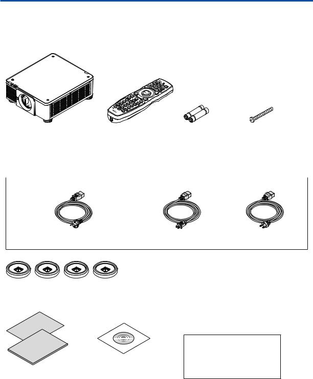
What’s in the Box?
Make sure your box contains everything listed. If any pieces are missing, contact your dealer. Please save the original box and packing materials if you ever need to ship your projector.
Projector
Dust cap for lens |
Remote control |
AA alkaline batteries |
Lens theft prevention |
* The projector is shipped without |
(7N901041) |
(x2) |
screw (79TM1071) |
a lens.For the types of lens and |
|
|
This screw makes it dif- |
throw distances,see page 172. |
|
|
ficult to remove the lens |
|
|
|
mounted on the projec- |
|
|
|
tor.(→ page 144) |
|
|
|
|
Power cord × 3 |
|
|
|
(79TM1021) |
(79TQ1001 for AC 120 V) |
(79TQ1011 for AC 200 V) |
For Europe/Asia/South America |
For North America |
|
4 Stacking holders (79TM1101)
When stacking projectors (double stacking),the tilt foot of the upper projector will be placed onto these stacking holders.(→ page 158)
• |
Important Infomation |
NEC Projector CD-ROM |
|
(7N8N7461) |
User’s manual (PDF) |
• |
Quick Setup Guide (7N8N7471) |
(7N952521) |
•Security Sticker
(Use this sticker when security password is set on.)
For North America only
Limited warranty
For customers in Europe:
You will find our current valid Guarantee Policy on our Web Site: www.nec-display-solutions.com
1
1. Introduction
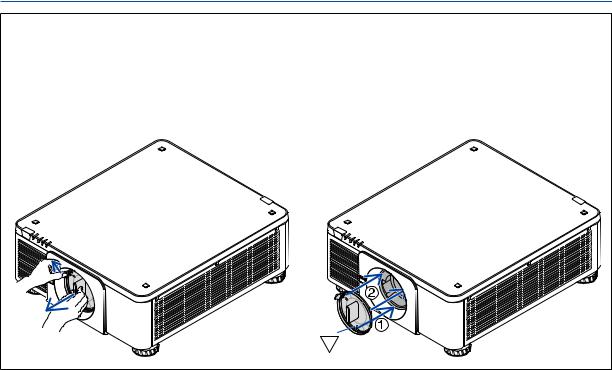
Attaching/Removing the Dust Cap
To remove the dust cap from the projector, push the tongue at the top left outward and pull the knob at the center of the cap.
To attach the dust cap to the projector, locate the catch on the lower end of the dust cap and place it into the opening of the projector with the point of a triangle mark ( ) facing downward ( in the figure below), and then push the upper end of the dust cap against the projector to place the catches into the slot while clutching the handle ( in the figure below).
2

1. Introduction
Introduction to the Projector
This section introduces you to your new projector and describes the features and controls.
General
•Single-chip DLP projector with high resolution and high brightness
Realized to project the image in the resolution 1920 × 1200 pixels (WUXGA), the aspect ratio in 16:10, and the brightness in 10000 lumens.
•Superior dust-proof structure
Adapted the cycle cooling system for cooling down the optical parts.By this system, air in the light source is cooled down and circulated.As the result, the optical parts are not exposed to the open air and enable to keep brightness without contamination by dust.
* Can not prevent contamination by dust completely.
Light source · Brightness
•A long-life laser diode is equipped in the light module
The product can be operated at low cost because the laser light source can be used for a long time without requiring replacement or maintenance.
•Brightness can be adjusted within a wide range
Unlike with ordinary light sources, the brightness can be adjusted from 20 to 100% in 1% increments.
•[CONSTANT BRIGHTNESS] mode
Brightness normally decreases with use, but by selecting [CONSTANT BRIGHTNESS] mode, sensors inside the projector detect and automatically adjust the output, thereby maintaining constant brightness throughout the life of the light module.
However, if brightness output is set at the maximum, brightness will decrease with use.
Installation
•Wide range of optional lenses selectable according to the place of installation
This projector supports 8 types of optional lenses, providing a selection of lenses adapted to a variety of places of installation and projection methods.
In addition, the lenses can be mounted and removed in one touch.
Note that no lens is mounted upon shipment from the factory. Please purchase optional lenses separately.
•This projector can be installed any angle within vertical and horizontal 360° range, however, life of optical parts will be shorten in the following installation state:
•When the projector is installed on which lens faces downward.
•When the intake vent on the projector side faces downward in the portrait installation. (See page 155)
•Double stackable for high light output projection
By stacking 2 projectors, increased brightness on a large screen is possible.
•Power lens control for quick and easy adjustment
By using buttons on the projector or the remote control, zoom, focus, and position (lens shift) can be adjusted.
Videos
•Wide range of input/output terminals (HDMI,DisplayPort,BNC,HDBaseT,etc.) and built-in monaural speaker
The projector is equipped with a variety of input/output terminals: HDMI, DisplayPort, BNC (5-core), computer (analog), HDBaseT, etc.
The projector’s HDMI input/output terminals and DisplayPort input terminal support HDCP.
HDBaseT, promoted and advanced by the HDBaseT Alliance, is a consumer electronic (CE) and commercial connectivity technology.
3
1. Introduction
•Slot for optional board
This projector has a slot for optional boards (sold separately).
•Simultaneous display of 2 images (PIP/PICTURE BY PICTURE)
Two images can be projected simultaneously with a single projector.
There are two types of layouts for the two images: “picture-in-picture” (PIP) in which a sub-picture is displayed on the main picture, and“picture-by-picture”(PICTURE BY PICTURE) in which the main and sub pictures are displayed next to each other.
•Multi-screen projection using multiple projectors
This projector is equipped with multiple HDMI input & output terminals that can connect multiple projectors in a daisy chain.By dividing and projecting high resolution image on each projector, high quality image can be realized.
Furthermore, the boundaries of the screens are smoothed using an edge blending function.
•Supports HDMI 3D format
This projector can be used to watch videos in 3D using commercially-available 3D emitters that support Xpand 3D and active shutter-type 3D eyewear.
Network
•Convenient utility software (User Supportware)
This projector supports our utility software (NaViSet Administrator 2, Virtual Remote Tool, etc.). NaViSet Administrator 2 helps you control the projector by a computer via wired LAN connection.
Virtual Remote Tool helps you perform operations by a virtual remote control such as projector's power on or off and signal selection via wired LAN connection. Moreover, it has function to send an image to the projector and register it as the logo data.
Please visit our web site for downloading each software. URL: http://www.nec-display.com/dl/en/index.html
•CRESTRON ROOMVIEW compatible
This projector supports CRESTRON ROOMVIEW,allowing multiple devices connected to the network to be managed from a computer or controller.
Energy-saving
•Energy-saving design with a standby power consumption of 0.30 watts or under
When the on-screen menu’s standby mode is set to “NORMAL”, the power consumption in the standby mode is 0.30 watts or under.
0.20 watts with power voltage AC110V-130V and 0.30 watts with power voltage AC200V-240V.
•“LIGHT MODE” for low power consumption and “Carbon Meter” display
The projector is equipped with an “LIGHT MODE” for reducing power consumption during use. Furthermore, the
power-saving effect when the LIGHT MODE is set is converted into the amount of reductions of CO2 emissions and this is indicated on the confirmation message displayed when the power is turned off and at “Information” on the on-screen menu (CARBON METER).
4

1. Introduction
About this user’s manual
The fastest way to get started is to take your time and do everything right the first time. Take a few minutes now to review the user’s manual. This may save you time later on. At the beginning of each section of the manual you’ll find an overview. If the section doesn’t apply, you can skip it.
5
1. Introduction
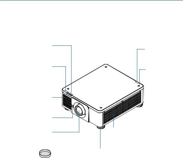
Part Names of the Projector
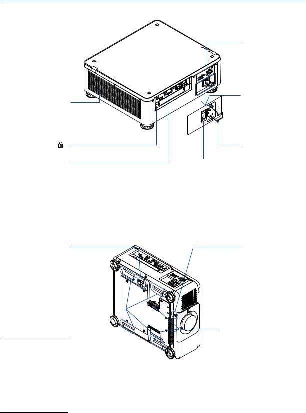
Front/Top
The lens is sold separately. The description below is for when the NP18ZL lens is mounted.
Indicator Panel
(→ page 8)
Remote Sensor (located on the front and the rear)
(→ page 12)
Intake vent Takes in air to cool the unit.
(→ page xi,155)
Lens Release (LENS) Button
(→ page 144)
Lens
Lens Cap
(The lens cap is attached to the lens.)
Remote Sensor
(→ page 12)
Stacking Holder fixing section
(4 locations)
Intake vent
Takes in air to cool the unit.
(→ page xi,155)
Tilt Foot
(→ page 32)
6
1. Introduction
Rear
Controls (→ page 8)
Exhaust vent |
|
Heated aiir is exhausted |
|
from here. |
|
(→ page xi,155) |
|
Built-in Security Slot ( |
)* |
Terminals |
|
(→ page 9) |
|
AC IN terminal Connect the supplied power cord’s three-pin plug here,and plug the other end into an active wall outlet.(→ page 14)
Power Cord Stopper
(→ page 16)
Main power switch
While AC power is being supplied,set the main power switch to ON position (|),then your projector will enter a standby state.
* This security slot supports the MicroSaver ® Security System.
Security Bar
Fixing a theft prevention device.
The security bar accepts security wires or chains up to 0.18 inch/4.6 mm in diameter.
Handle (located on 4 posi-  tions)

For transportation
NOTE:
•For moving the projector, make sure you have at least two people. At the same time, do not grip and hold the projector other than by these handles. Attempting to move the projector alone could result in back pain or other injuries.
Theft prevention screw hole for the lens unit
Intake vent |
Takes in air to cool the unit. |
(→ page xi,155) |
7
1. Introduction
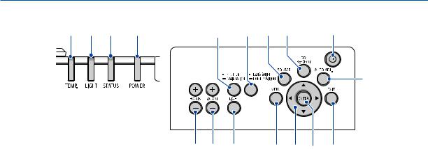
Controls/Indicator Panel
5 |
4 |
3 |
2 |
13 |
15 |
6 |
8 |
1 |
7
1. (POWER) Button
(→ page 18, 34)
2.POWER Indicator
(→ page 17, 18, 34, 178)
3.STATUS Indicator
(→ page 178)
4.LIGHT Indicator
(→ page 39, 179)
5.TEMP. Indicator
(→ page 179)
6.SOURCE Button
(→ page 20)
7.AUTO ADJ. Button
(→ page 33)
8.3D REFORM Button
(→ page 42)
9.MENU Button
(→ page 80)
10.▲▼ Buttons
(→ page 80)
11.ENTER Button
(→ page 80)
12.EXIT Button
(→ page 80)
16 17 |
14 |
9 |
10 11 |
12 |
13.SHUTTER/CALIBRATION Button
(→ page 36)
14.LIGHT Button
(→ page 39)
15.LENS SHIFT/HOME POSITION Button
(→ page 23, 60, 164)
16.FOCUS +/− Button
(→ page 26)
17.ZOOM +/− Button
(→ page 31)
8
1. Introduction
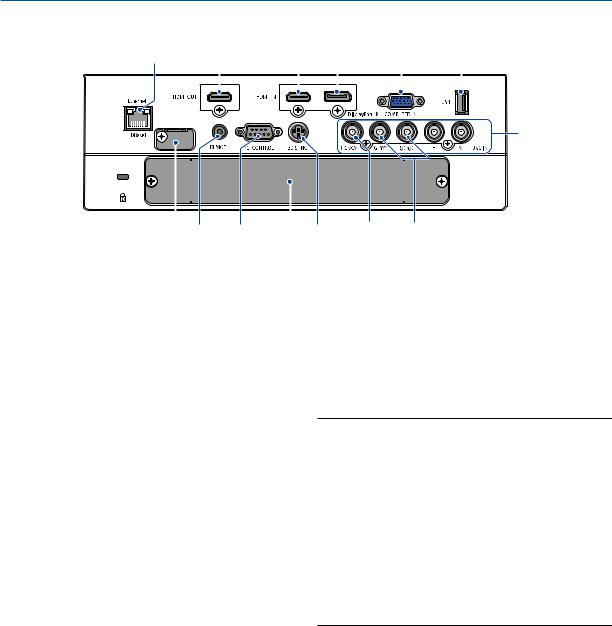
Terminals Features
9 |
8 |
3 |
2 |
|
|
1 |
7 |
|||||||||
|
|
|
|
|
|
|
|
|
|
|
|
|
|
|
|
|
|
|
|
|
|
|
|
|
|
|
|
|
|
|
|
|
|
|
|
|
|
|
|
|
|
|
|
|
|
|
|
|
|
|
|
|
|
|
|
|
|
|
|
|
|
|
|
|
|
|
|
4
|
|
|
|
|
|
|
6 |
5 |
|
|
|
|
|
|
|
||
14 |
12 |
11 |
13 |
10 |
||||
1.COMPUTER IN (Mini D-Sub 15 Pin)
(→ page 14, 145, 151, 175)
2.DisplayPort IN Terminal (DisplayPort 20 Pin)
(→ page 146, 175)
3.HDMI IN Terminal (Type A)
(→ page 146, 148, 152, 175)
4.BNC IN [R/Cr/CV, G/Y/Y, B/Cb/C, H,V] Terminals (BNC × 5)
(→ page 145, 150)
5.BNC (Y/C) Input Terminal (BNC × 2)
(→ page 150)
6.BNC (CV) Input Terminal (BNC × 1)
(→ page 150)
7.USB Port (Type A)
(→ page 176)
(For future expansion.This port allows for power supply.)
8.HDMI OUT Terminal (Type A)
(→ page 149)
9.Ethernet/HDBaseT Port (RJ-45)
(→ page 153, 154, 176)
12.REMOTE Terminal (Stereo Mini)
Use this jack for wired remote control of the projector using a commercially available remote cable with 3.5 stereo mini-plug (without resistance).
Connect the projector and the supplied remote control using a commercially available wired remote control cable.
(→ page 12)
NOTE:
•When a remote control cable is connected to the REMOTE terminal, infrared remote control operations cannot be performed.
•Power cannot be supplied from the REMOTE terminal to the remote control.
•When [HDBaseT] is selected in the [REMOTE SENSOR] and the projector is connected to a commercially-available transmission device that supports HDBaseT, remote control operations in infra-red cannot be carried out if transmission of remote control signals has been set up in the transmission device. However, remote control using infrared rays can be carried out when the power supply of the transmission device is switched off.
10.3D SYNC Terminal (Mini DIN 3 Pin)
(→ page 48)
11.PC CONTROL Port (D-Sub 9 Pin)
(→ page 176, 183)
Use this port to connect a PC or control system. This enables you to control the projector using serial communication protocol. If you are writing your own program, typical PC control codes are on page 183.
13.SLOT
(→ page 165)
14.Service terminal
For service only
9
1. Introduction
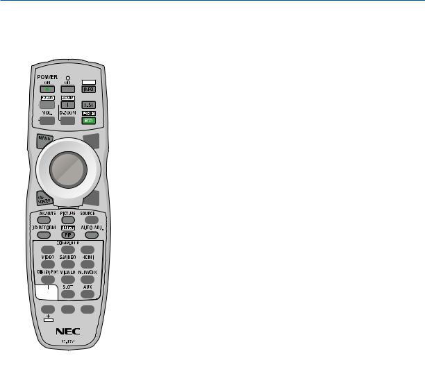
Part Names of the Remote Control
1 |
|
1. |
Infrared Transmitter |
21. AUTO ADJ. Button |
|
|
|
|
(→ page 12) |
(→ page 33) |
|
4 |
|
2. |
Remote Jack |
22, 23. COMPUTER 1/2 Button |
|
3 |
5 |
|
Connect a commercially available |
(→ page 20) |
|
|
|
remote cable here for wired opera- |
24. COMPUTER 3 Button |
||
|
|
|
|||
6 |
8 |
|
tion. (→ page 12) |
(This button is not work on this |
|
9 |
3. |
POWER ON Button |
projector.) |
||
7 |
|
(→ page 18) |
25. VIDEO Button |
||
|
|
||||
10 |
11 |
4. |
POWER OFF Button |
(→ page 20) |
|
12 |
|
|
(→ page 34) |
26. S-VIDEO Button |
|
13 |
5. |
INFO/L-CALIB. Button |
(→ page 20) |
||
|
|
Display the [SOURCE(1)] screen |
27. HDMI Button |
||
14 |
15 |
|
of the on-screen menu. |
(→ page 20) |
|
|
(→ page 18, 139) |
28. DisplayPort Button |
|||
16 |
17 |
|
|||
6. |
VOL./FOCUS +/− Buttons |
||||
(→ page 20) |
|||||
20 |
18 |
|
(→ page 26) |
29. VIEWER Button |
|
21 |
|
||||
19 |
7. |
D-ZOOM/ZOOM +/− Buttons |
|||
(The VIEWER button will not work |
|||||
23 |
24 |
|
(→ page 38) |
||
|
on this series of projectors.) |
||||
22 |
26 |
|
|||
8. |
TEST Button |
|
|||
25 |
27 |
30. NETWORK Button |
|||
28 |
30 |
|
(→ page 88) |
(→ page 20) |
|
29 |
9. |
ECO/L-SHIFT Button |
31. SLOT Button |
||
32 |
|||||
|
|
(→ page 25, 39) |
|||
31 |
|
(→ page 20, 165) |
|||
33 |
|
||||
10. MENU Button |
|||||
34 |
36 |
32. ID SET Button |
|||
|
35 |
|
(→ page 80) |
(→ page 127) |
|
|
|
11. |
EXIT Button |
33. Numeric (0 to 9/CLEAR) But- |
|
|
|
|
(→ page 80) |
||
2 |
|
|
tons |
||
|
12. ENTER Button |
(→ page 127) |
|||
|
|
|
(→ page 80) |
(The AUX button will not work on |
|
|
|
13. |
▲▼ Button |
this series of projectors.) |
|
|
|
|
(→ page 80) |
34. CTL Button |
|
|
|
14. ON-SCREEN Button |
This button is used in conjunction |
||
|
|
|
(→ page 36) |
with other buttons, similar to a |
|
|
|
15. SHUTTER Button |
CTRL key on a computer. |
||
|
|
35. LIGHT Button |
|||
|
|
|
(→ page 36) |
||
|
|
16. AV-MUTE Button |
This button is used to turn on the |
||
|
|
backlight for the remote control |
|||
|
|
|
(→ page 36) |
||
|
|
|
buttons. |
||
|
|
17. |
PICTURE Button |
||
|
|
The backlight will turn off if no |
|||
|
|
|
(→ page 92, 94) |
||
|
|
|
button operation is made for 10 |
||
|
|
|
|
||
|
|
18. SOURCE Button |
seconds. |
||
|
|
|
(→ page 20) |
36. HELP Button |
|
|
|
|
|
||
|
|
19. |
3D REFORM Button |
(→ page 139) |
|
|
|
|
(→ page 42) |
|
|
20.PIP/FREEZE Button
(→ page 37, 71)
10
1. Introduction
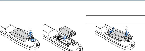
Battery Installation
1.Press the catch and remove the battery cover.
2.Install new ones (AA). Ensure that you have the batteries’ polarity (+/−) aligned correctly.
3.Slip the cover back over the batteries until it snaps into place.
NOTE: Do not mix different types of batteries or new and old batteries.
2 |
1 |
2 |
|
1 |
|
Remote Control Precautions
•Handle the remote control carefully.
•If the remote control gets wet, wipe it dry immediately.
•Avoid excessive heat and humidity.
•Do not short, heat, or take apart batteries.
•Do not throw batteries into fire.
•If you will not be using the remote control for a long time, remove the batteries.
•Ensure that you have the batteries’ polarity (+/−) aligned correctly.
•Do not use new and old batteries together, or use different types of batteries together.
•Dispose of used batteries according to your local regulations.
11
1. Introduction
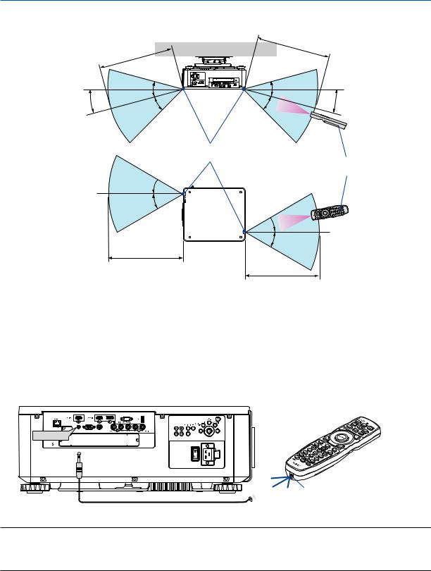
Operating Range for Wireless Remote Control
7m/276 |
inch |
|
7 |
m/276 |
inch |
|
||
|
|
15° |
30° |
30° |
15° |
|
30° |
30° |
|||
|
|
Remote sensor on projector cabinet
Remote control
30° 
30°
 30°
30°
30°
7 m/276 inch
7 m/276 inch
•The infrared signal operates by line-of-sight up to a distance of above meters and within a 60-degree angle of the remote sensor on the projector cabinet.
•The projector will not respond if there are objects between the remote control and the sensor, or if strong light falls on the sensor. Weak batteries will also prevent the remote control from properly operating the projector.
Using the Remote Control in Wired Operation
Connect one end of the remote cable to the REMOTE terminal and the other end to the remote jack on the remote control.
REMOTE


 Remote Jack
NOTE:
•When a remote cable is inserted into the REMOTE terminal, the remote control does not work for infrared wireless communication.
•Power will not be supplied to the remote control by the projector via the REMOTE jack. Battery is needed when the remote control is used in wired operation.
12

2. Projecting an Image (Basic Operation)
This section describes how to turn on the projector and to project a picture onto the screen.
Flow of Projecting an Image
Step 1
• Connecting your computer / Connecting the power cord (→ page 14)
Step 2
• Turning on the projector (→ page 17)
Step 3
• Selecting a source (→ page 20)
Step 4
•Adjusting the picture size and position (→ page 22)
•Correcting keystone distortion [CORNERSTONE] (→ page 42)
Step 5
•Adjusting a picture
- Optimizing a computer signal automatically (→ page 33)
Step 6
• Making a presentation
Step 7
• Turning off the projector (→ page 34)
Step 8
• After use (→ page 35)
13
 Loading...