

Window (Room) Air Conditioner
User Manual
RWC-3217
RWC-4717
SWINGSWING
FAN
SPEED
TIMER
F
HR
/
OFFON
MODE
Thank you very much for purchasing Air Conditioner.
Before please read this User
Manual
installing and using this appliance,
carefully, and keep it for future reference.

CONTENTS
Safety Precautions
Parts Name
Operating Instructions
Care and Maintenance
Operation Tips
Trouble Shooting
Installation Instructions
2
3
5
8
9
10
11
1
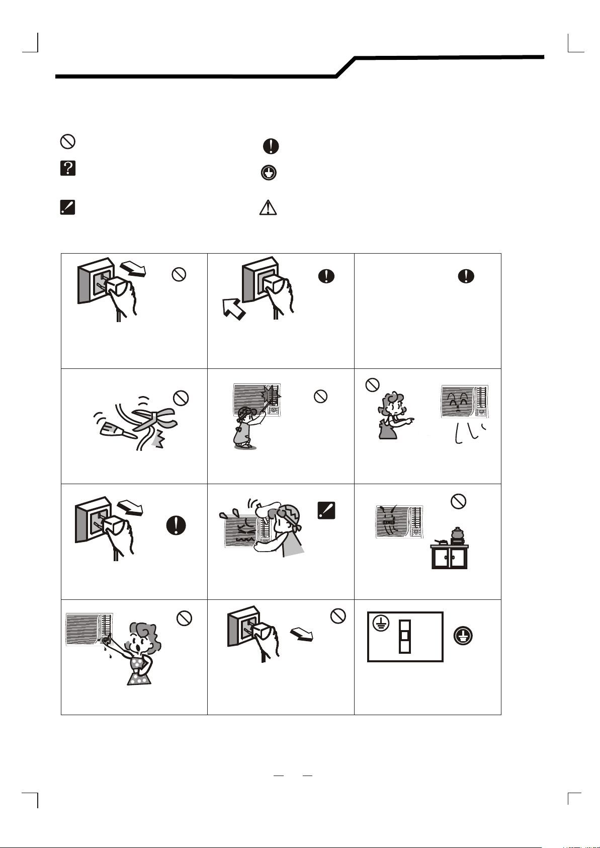
Safety Precautions
Symbols in this User's Manual are interpreted as shown below:
Be sure not to do.
The feature of the appliance,
instead of a fault.
Pay attention to such a situation.
Do not use the power supply circuit
breaker or pull off the plug to turn it off
during operation. This may cause a fire
due to spark, etc.
Keep the power supply circuit breaker
or plug from dirt. Connect the power
supply cord to it firmly and correctly,
lest an electric shock or a fire break out
due to insufficient contact.
Be sure to follow the instruction.
Grounding is necessary.
Warning: Incorrect handling could
cause a serious hazard, such as death,
serious injury,etc.
Use correct power supply according to the
rating plate.
Otherwise, serious faults maybe occur
or a fire maybe break out.
G
G
N
N
I
I
W
W
S
S
F F
HRHR
N
A
F
E
D
E
S
P
/
R
E
M
I
T
ON
OF
F
D
E
M
O
I
I
N
N
G
G
W
W
S
S
F F
HRHR
N
F
A
D
E
P
E
S
/
R
I
M
E
T
ON
OF
F
E
O
D
M
Do not knit, pull or press the power supply
cord, lest the power supply cord be broken.
An electric shock or fire is probably caused
by a broken power supply cord.
Turn off the appliance first before cutting
off power supply when malfunction occurs.
G
G
I
I
W
W
N
N
S
S
F F
HRHR
N
F
A
D
E
S
P
E
/
R
E
I
M
T
ON
OF
F
E
D
M
O
Do not touch the operation buttons
when your hands are wet.
Never insert a stick or similar to the unit.
Since the fan rotates at high speed, this
may cause an injury.
I
I
N
N
G
G
W
W
S
S
F F
HRHR
N
F
A
D
E
P
E
S
/
R
I
M
T
E
ON
OF
F
E
O
D
M
Do not repair the appliance by yourself.
If this is done incorrectly, it may cause
an electric shock, etc.
Pull off the plug to stop it when
the operation is abnormal
( a peculiar odor is smelled, etc.),
or it may cause an electric shock, etc.
It is harmful to your health if the cool air
reaches you for a long time. It is advisable
to let the air flow be deflected to all the room.
G
G
N
N
I
I
W
W
S
S
F F
HRHR
N
A
F
E
D
E
S
P
/
R
M
E
I
T
ON
OF
F
D
E
O
M
Prevent the air flow from reaching the gas
burners and stove.
It is the user's responsibility to make the
appliance be grounded according to
local codes or ordinances by a licenced
person.
2
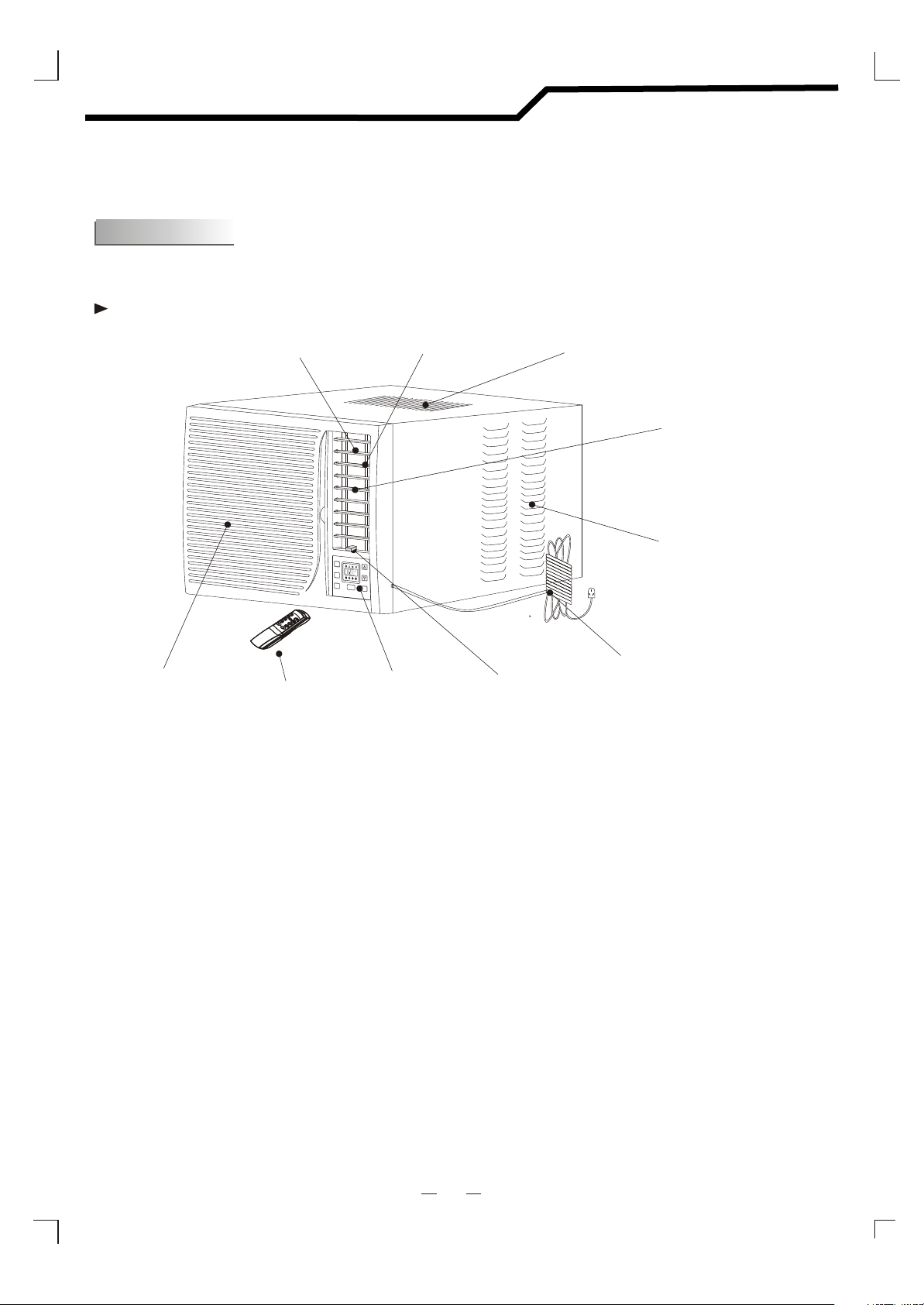
Parts Name
Front view
For remote control model
Interior
Air Inlet
Grille
Air Outlet
Remote Controller
Vertical Air Vane
S
S
WI
WI
N
N
G
G
FF
F
HRHR
A
N
S
P
E
E
D
T
I
M
E
R
ON
/
OFF
M
O
D
E
Control Panel
Exterior Air Inlet
Horizontal Air Vane
Exterior Air Inlet
ÅÅË®×ì
Power Cord
Fresh air lever
Fig. 1
Note: The figure in this manual are based on the external view of a standard model.
Consequently, the shape may differ from that of the air conditioner you have selected.
3
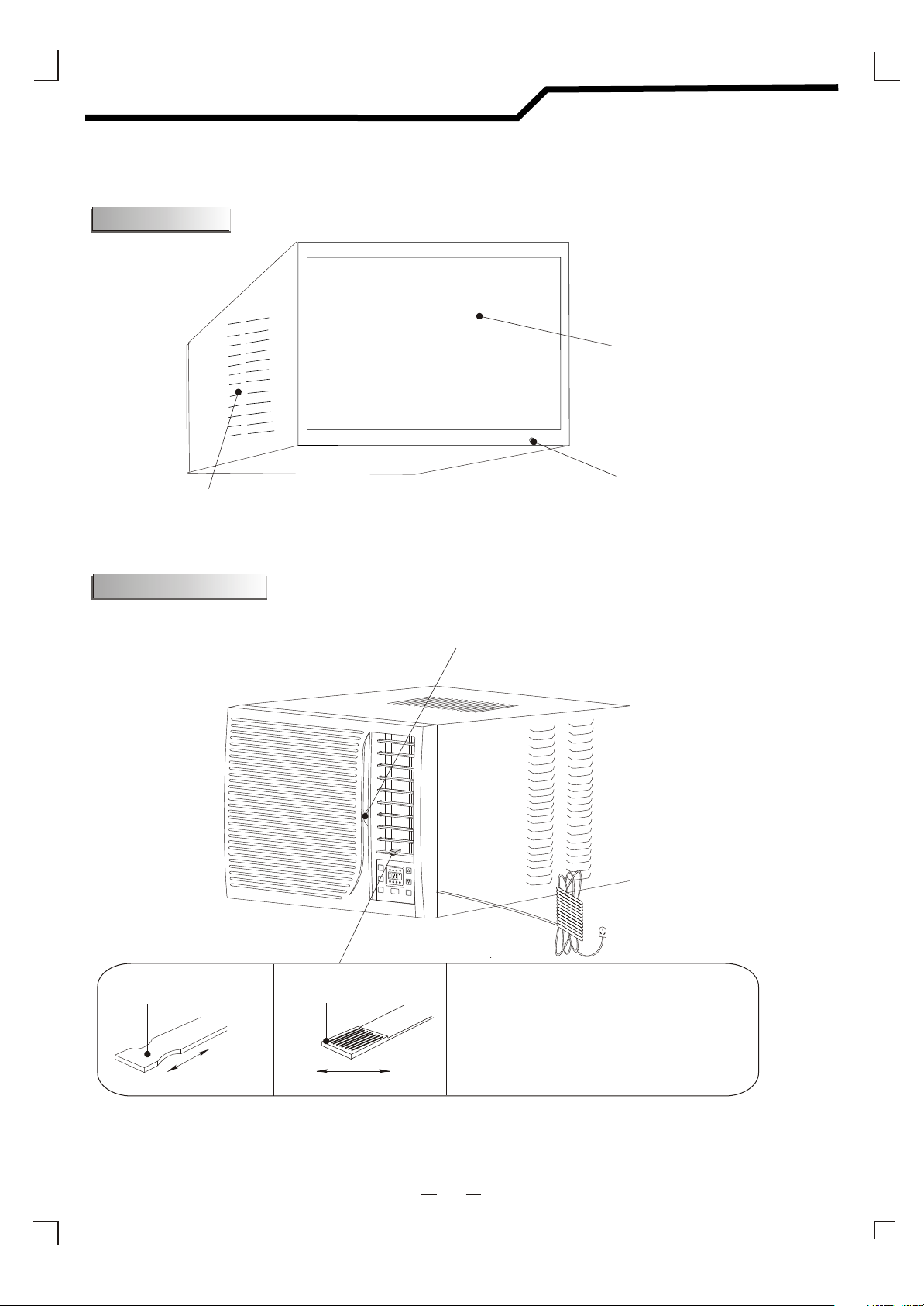
Parts Name
Back view
1.Accessories
Exterior Air Inlet
Outside Air Outlet
Drainage Tip
ÅÅË®×ì
Fresh air lever
Fresh air lever
Push in
S
S
W
W
I
I
N
N
G
G
F
A
N
S
P
E
E
D
T
I
M
E
R
Fresh air lever
Air Filter handle
FF
HRHR
ON
/
OFF
M
O
D
E
Shut the fresh air door to achieve the best
cooling effect and open it to introduce fresh
air into the room if the air is foul inside .
Pull out
Fig.1 Fig.2
SHUT OPEN
4

Operating Instructions
Remote Control Model
You can easily operate this air conditioner by pressing
relevant button on the control panel as well as the
remote controller.
ON/OFF button
The air conditioner will be started when it is energized
or will be stopped when it is in operation, if you press
this button.
MODE button
Each time MODE button is pressed, the operation
mode is changed in sequence:
COOLING FAN ONLY ENERGY SAVING COOLING
NOTE: After setting the mode, allow 3
minutes before switching to another mode.
FAN SPEED button
Used to select fan speed in sequence auto, low,
medium and high.
TIMER button
Used to set or cancel timer operation.
When the unit is in operation, you can set OFF TIMER.
When the unit is off, you can set ON TIMER.
Timer setting range is 0 to 24 hours.
Control Panel
SWING
SWING
CC
F
FAN
SPEED
TIMER
HR
/
OFFON
MODE
Indication symbols of LED on control panel:
Auto fan speed Cooling
Low fan speed
Medium fan speed
Fan only
Timer
Display set temp
Display set timer
C
HR
If the OFF TIMER is set, the timer LED displays
High fan speed
Energy-saving
the remaining time to turn off the unit for only
12 seconds, then LED shifts to display set temperature.
Above LED lights on when the relevant mode is in used.
If the ON TIMER is set, the timer LED displays
the remaining time to turn on the unit.
If you want to cancel ON TIMER, press TIMER button again.
Button
Used to set room temperature in COOLING mode or used to set time in TIME R mode.
If the two keys are pressed at the same time,the temperature LED display will alternate between
and .
But the mark of " "or" "you can not change.Usually ,those models used 220V~/50Hz marked with
" ",others models marked with " ".
NOTE: Temperature setting range is from 19 (66 ) to 31 (88 ).
SWING button
Used to select start or stop vertical air vanes swinging.
5

Operating Instructions
Remote Controller
The remote controller transmits signals to the system.
10
1
Power
Timer
2
Mode
Swing
Power Saver
8
9
POWER Buttom
1
The appliance will start when it is
energized or will stop when it is
in operation, if you press this button.
MODE Buttom
2
Used to select the operation mode.
7
Auto
Fan Speed
Mid
4
High Low
3
_
Temp/Time
+
5
6
Buttoms
3
Used to set room temperature in COOLING
mode or used to set time in TI MER mode.
HIGH Buttom
4
Used to select the mode.high fan speed
MID Buttom
5
Used to select the Mid mode.fan speed
LOW Buttom
6
Used to select the Low mode.fan speed
AUTO Buttom
7
Used to select the Auto mode. fan speed
TIMER Buttom
8
Used to set or cancel timer operation..
POWER Buttom
9
Used to select the mode.Energy-saving
10
SWING Buttom
Used to select start or stop vertical air vanes swinging.
Changing modes during operation, sometimes the unit does not response at once. Wait 3 minutes.
Wait 3 minutes before restarting the appliance.
6

Operating Instructions
Remote control
How to Insert the Batteries
Remove the battery cover according to the arrow direction.
Insert new batteries making sure that the (+) and (-) of battery
are matched correctly.
Reattach the cover by sliding it back into position.
Note:
Use 2 LR6 AA(1.5volt) batteries. Do not use rechargeable batteries. Replace batteries with new ones of the same type when the display becomes dimor effective resoponce.
If the replacement is done within 1 minute, the remote control will keep
original presetting.
How to Use
To operate the room air conditioner , aim the remote control
to the signal receptor.
The remote control will operate the air conditioner at a distance of up to 23 feet when pointing at signal receptor of indoor
unit.
S
S
W
W
I
I
N
N
G
G
FF
F
HRHR
A
N
S
P
E
E
D
T
I
M
E
R
ON
/
OFF
M
O
D
E
Signal receptor
7

Care and Maintenance
Front panel maintenance
Unplug from power source
Unplug from power
source after switch off
the air conditioner.
Wipe with a soft and dry cloth
Use lukewarm water
(below 40 C) to clean
if the air conditioner
is very dirty.
Use a dry and
soft cloth to
clean it.
Air filter maintenance
Stop operation and
take out air filter.
Take out air filter as shown
G
G
N
N
I
I
W
W
S
S
F F
HRHR
A
N
F
E
D
P
E
S
/
R
M
E
T
I
ON
OFF
E
D
O
M
Clean and reinstall the air filter.
If the dirt is conspicuous,
wash it with a solution of
detergent in lukewarm water.
After cleaning, dry well in
shade.
Never use volatile substance
such as gasoline or polishing
powder to clean the appliance.
8

Operation Tips
Operating condition
Noise pollution
The protective device maybe trip and stop
the appliance in the cases listed below.
COOLING
Outdoor air temperature is over *43 c
Room temperature is below 18 c
o
o
The noise level of air conditioner sounds
higher at night than in the daytime.
Please set (LOW FAN SPEED) or
(FAN ONLY) mode at night in order
*For Tropical (T3) Climate condition models, the
temperature point is 52 instead of 43 .
If the air conditioner runs in COOLING or DRY mode with
door or window opened for a long time when relative
humidity is above 80%,dew may drip down from the outlet.
to decrease noise.
Features of protector
The protective device will work at following cases.
Restarting the unit at once after operation stops or changing mode during operation, you need to
wait 3 minutes.
Connect to power supply and turn on the unit at once, it may start 20 seconds later.
Caution
Use proper fuse
Do not use wire or anything else instead of fuse. Otherwise, air conditioner will be damaged,
or cause stock, fire, etc.
You need to wait 3 minutes before restarting.
(Note : If you let the appliance on after power cut, the compressor may be burned)
9

Trouble Shooting
1.Accessories
The following cases may not always be a malfunction, please check it before
asking for service.
Trouble
Does not run
Not cool enough
Peculiar odor
Sound of
flowing water
Analysis
If the protector trip or fuse is blown.
Please wait for 3 minutes and start again,
protector device may be preventing unit to work.
.
If batteries in the remote controller exhausted.
If the plug is not properly plugged.
Is the air filter dirty?
Are the intakes and outlets of the air
I
I
G
G
N
N
W
W
S
S
F F
HRHR
N
F
A
D
E
E
P
S
/
E
R
M
T
I
ON
OF
F
E
D
O
M
I
I
G
G
N
N
W
W
S
S
F F
HRHR
N
F
A
D
E
E
P
S
/
R
E
T
I
M
ON
OF
F
E
D
O
M
G
G
N
N
W
W
I
I
S
S
F F
HRHR
N
A
F
D
E
E
P
S
/
E
R
M
I
T
ON
OF
F
E
D
O
M
conditioner blocked
Is the temperature set properly
Is the fresh air lever shut off
Is the door or windows closed
This odor may come from another source
such as furniture, cigarette etc, which is
sucked in the unit and blows out with the air.
Caused by the flow of refrigerant in the
air conditioner, not a trouble.
Cracking sound
Spray mist from
the outlet
The sound may be generated by the expansion
G
G
N
N
W
W
I
I
S
S
F F
HRHR
N
A
F
D
E
E
P
S
/
E
R
M
I
T
ON
OF
F
E
D
O
M
or contraction of the front panel due to change
of temperature.
Mist appears when the room air becomes
very cold because of cool air discharged
G
G
N
N
W
W
I
I
S
S
F F
HRHR
N
A
F
D
E
E
P
S
/
E
R
M
I
T
ON
OF
F
E
D
O
M
from indoor unit during COOLING or DRY
operation mode.
10

Installation Instructions
1.Accessories
Installation accessories
Note: All mentioned accessories are prepared or purchased by user.
RWC-3217
40
550
5
7
3
50
600
10
20
5
1. buffer 2.leveling pad
3
2
3. seal foam pad
15
Note: All mentioned accessories are prepared or purchased by user.
RWC-4717
700
40
68
4
20
10
2
5
3
454
4. decorating strip
50
750
550
1. Buffer
2.leveling pad
11
15
3. seal foam pad
4. decorating strip

Installation Instructions
Installation Requirements
2. Installation requirements
1.Accessories
Leave a space more than 100 cm at the rear of the appliance and ensure the outdoor air intake not
be blocked.
A wooden frame as shown in fig.1 is advisable if the appliance is installed through a window. The
installation bracket as shown in fig.2 should not be welded with the window sash.
The square hole should be smooth enough if the appliance is installed through a wall. A space
as shown in fig.3 for outdoor air intake should be prepared if the wall is too thick.
The metallic installation bracket should be constructed as fig.4.
All the installation structure should be strong enough.
RWC-3217
RWC-4717
90
539
Fig.1
Fig.2
90
710
Fig.1
A
384
384
A A
90x20x539
wooden strip
539
740
Space for outdoor
A
20
0
8
1
air intake
Fig.3
85
thickness of wall
90
15~20
Fig.4
A
510
510
A A
90x20x710
wooden strip
710
910
Space for outdoor
A
20
0
8
1
air intake
0
Fig.3
9
Fig.2
85
thickness of wall
20~30
Fig.4
12

Installation Instructions
1.Accessories
Installation Steps
Test the appliance by plugging the power supply cord in a correct outlet of power source
before installation.
A clearance of 20 mm is advisable between the appliance cabinet and the wall. Fix the indoor air intake
panel with the cabinet by employing two screws which packed in the packing bag as shown in Fig.5.
Put the buffers on the installation bracket as shown in Fig.6. Adjust the appliance as shown in Fig.4.
The leveling pads are employed to tilt the appliance in order that the indoor side is about (15 20) mm
higher than the outdoor side for fear the condensate overflow into the room.
The seal foam pads are employed to prevent outside air from leaking into the room (Fig.7) and the
decorating strip is presented for aesthetical appearance as Fig.8.
1.Accessories
lower part of
installation bracket
buffer
N
N
G
G
I
I
S
S
W
W
F F
HRHR
N
F
A
D
E
E
S
P
/
R
E
M
T
I
ON
OF
F
E
D
O
M
Fig.5
G
G
N
N
I
I
S
S
W
W
F F
HRHR
N
A
F
D
E
E
P
S
/
E
R
M
I
T
ON
OF
F
D
E
M
O
Fig.6
G
G
N
N
I
I
W
W
S
S
N
A
F
D
E
E
P
S
E
R
M
I
T
F F
HRHR
/
ON
OF
F
E
O
D
M
Decorating strip
Fig.7
Fig.8
1.Accessories
Drainage
Condensate will form during the cooling or dry operation, user can choose drainage
or no drainage. Remove the drainage tip and fix the drainage hose when drainage is chosen.
On the contrary, the condensate is splashed to cool the condenser so that the cooling capacity
and energy conservation is improved with a little high noise when no drainage is chosen.
1.Accessories
Fuse and Grounding
A proper time-delay fuse should be employed in the power supply circuit.
For your personal safety, this air conditioner must be grounded.
The extension of power supply cord is inadvisable.
Connect this air conditioner to its own individual wall receptacle to prevent itself and other appliances
or household lights from causing a overload that could cause a power outage.
13

NEC Australia Pty. Ltd
ABN 86 001 217 527
Home Electronics Group
NEC Service Centres
NEW South Wales
Sydney 184 Milperra Rd, Revesby 2212 (02) 9780 8688
Newcastle 120 Parry Street, Newcastle 2302 (02) 4926 2466
Victoria
Melborne 480 Princes Highway, Noble Park 3174 (03) 9554 6245
Queensland
Brisbane 116 Ipswich Rd, Woollongabba 4102 (07) 3361 5858
Southport Shop 1, 48 Ferry Rd, Southport 4215 (07) 5591 3670
South Australia
Adelaide 84A Richmond Rd, Keswick, 5053 (08) 8375 5710
Western Australia
Perth 45 Sarich Courl, Osborne Park 6017 (08) 9445 5901
For Service in outer areas, please contact your retailer for the address
of the nearest Authorized NEC Service Centre.
NEC Australia Pty. Ltd.
244 Beecroft Road EPPING 2121
Tel. 131- 632 Fax. (02) 9930 2380
Version No 819043161-01 .
 Loading...