


NEC R 37 Xtra User Manual
R
37
Xtra
37
Xtra
79TH1624
Printed in Japan
Itasca, Illinois 60143-1248
1250 N. Arlington Heights Road, Suite 500
NEC Technologies, Inc.
1993 by NEC Technologies, Inc.
NEC is registered trademark of NEC Corporation.
MultiSync is a registered trademark of NEC Technologies, Inc. in the U.S.A.
R
37
Xtra
Multimedia Monitor
User's Manual
37
Xtra
R
1
CAUTION
RISK OF ELECTRIC SHOCK
DO NOT OPEN
CAUTION: TO REDUCE THE RISK OF ELECTRIC SHOCK, DO
NOT REMOVE COVER. NO USER-SERVICEABLE
PARTS INSIDE. REFER SERVICING TO QUALIFIED
SERVICE PERSONNEL.
This symbol warns the user that uninsulated voltage within the unit may
have sufficient magnitude to cause electric shock. Therefore, it is dangerous to make any kind of contact with any part inside of this unit.
This symbol alerts the user that important literature concerning the operation and maintenance of this unit has been included. Therefore, it should
be read carefully in order to avoid any problems.
WARNING
TO PREVENT FIRE OR SHOCK HAZARDS, DO NOT EXPOSE THIS UNIT TO
RAIN OR MOISTURE. ALSO DO NOT USE THIS UNIT'S POLARIZED PLUG
WITH AN EXTENSION CORD RECEPTACLE OR OTHER OUTLETS, UNLESS
THE PRONGS CAN BE FULLY INSERTED. REFRAIN FROM OPENING THE
CABINET AS THERE ARE HIGH-VOLTAGE COMPONENTS INSIDE. REFER
SERVICING TO QUALIFIED SERVICE PERSONNEL.
DOC compliance Notice
This Class B digital apparatus meets all requirements of the Canadian
Interference-Causing Equipment Regulations.
WARNING
This equipment has been tested and found to comply with the limits for a
Class B digital device, pursuant to Part 15 of the FCC Rules. These limits are
designed to provide reasonable protection against harmful interference in
a residential installation. This equipment generates, uses, and can radiate
radio frequency energy and, if not installed and used in accordance with
the instructions, may cause harmful interference to radio communications.
However, there is no guarantee that interference will not occur in a
particular installation. If this equipment does cause harmful interference to
radio or television reception, which can be determined by turning the
equipment off and on, the user is encouraged to try to correct the
interference by one or more of the following measures:
• Reorient or relocate the receiving antenna.
• Increase the separation between the equipment and receiver.
• Connect the equipment into an outlet on a circuit different from that to
which the receiver is connected.
• Consult the dealer or an experienced radio / TV technician for help.
As an E
NERGY STAR ® partner, NEC Technologies has determined that this product
meets the E
NERGY STAR is a U.S. registered mark.
E
NERGY STAR ® guidelines for energy efficiency.
Warnings and Safety Precaution
The NEC MultiSync Multimedia monitors XP37 Xtra and XM37 Xtra are designed and manufactured to provide long, trouble-free service. No maintenance other than cleaning is required. Use a soft cloth and if necessary, mild
detergent. Do not use commercial spray cleaners which may damage the
surface. In case of damage, arrange for repairs at an authorized NEC Service Center.
For operating safety and to avoid damage to the unit, read carefully and
observe the following instructions.
To avoid shock and fire hazards:
1. Provide adequate space for ventilation to avoid internal heat build-up.
Do not cover rear vents or install in a closed cabinet or shelves.
The unit is equipped with cooling fans on the top. If you enclose the unit in
a cabinet or rack, be sure there is adequate space at the top and rear of
the unit to allow heated air to rise and escape. A cabinet or shelves in
which the unit is placed must be maintained below 40°C
2. Do not use the power cord polarized plug with extension cords or outlets
unless the prongs can be completely inserted.
3. Do not expose unit to rain or moisture.
4. Avoid damage to the power cord, and do not attempt to modify the
power cord. Do not place the unit on the power cord. Damage to the
cord may cause shock or fire.
Handle the power cord carefully and avoid excessive bending. A
damaged cord can cause electric shock or fire.
5. Unplug unit during electrical storms or if unit will not be used over a long
period.
6. Do not open the cabinet which has potentially dangerous high voltage
components inside. If the unit is damaged in this way the warranty will be
void. Moreover, there is a serious risk of electric shock.
7. Do not attempt to service or repair the unit. NEC is not liable for any bodily
harm or damage caused if unqualified persons attempt service or open
the back cover. Refer all service to authorized NEC Service Centers.
To avoid damage and prolong operating life:
1. Use only with 100-120V/220-240V 50/60Hz AC power supply. Continued
operation at line voltages other than 100-120V/220-240 Volts
shorten the life of the unit, and might even cause a fire hazard.
2. Handle the unit carefully when moving and do not drop.
3. Locate set away from heat, excessive dust, and direct sunlight.
4. Protect the inside of the unit from liquids and small metal objects. In case
of accident, unplug the unit and have it serviced by an authorized NEC
Service Center.
5. Unplug unit before cleaning. Use only a soft cloth and mild detergent.
Commercial household sprays and cleaners may damage the CRT surface and cabinet.
7. Do not place liquids on top of the unit. If liquid has been spilled into the
unit, unplug the unit and have it serviced by an authorized NEC Service
Center.
8. This unit is designed for indoor installation use only. Do not use the unit
for purposes other than originally intended.
9. Do not use the unit on an unstable surface.
10.Do not set the unit on end when in use or stock.
11.Rest your eyes periodically.
AC will
2
ATTENTION
RISQUE D’ELECTROCUTION
NE PAS OUVRIR
MISE EN GARDE: AFIN DE REDUIRE LES RISQUES D’ELECTRO-
CUTION, NE PAS DEPOSER LE COUVERCLE, IL
N’Y A AUCUNE PIECE UTILISABLE A L’INTERIEUR
DE CET APPAREIL. NE CONFIER LES TRAVAUX
D’ENTRETIEN QU’A UN PERSONNEL QUALIFIE.
Ce symbole a pour but de prévenir l’utilisateur de la présence
d’une tension dangereuse, non isolée se trouvant à l’intérieur de
l’appareil. Elle est d’une intensité suffisante pour constituer un
risque d’électrocution. Eviter le contact avec les pièces à
l’intérieur de cet appareil.
Ce symbole a pour but de prévenir l’utilisateur de la présence
d’importantes instructions concernant l’entretien et le
fonctionnement de cet appareil. Par conséquent, elles doivent
être lues attentivement afin d’éviter des problèmes.
AVERTISSEMENT
AFIN DE REDUIRE LES RISQUES D’INCENDIE OU D’ELECTROCUTION, NE PAS
EXPOSER CET APPAREIL A LA PLUIE OU A L’HUMIDITE. AUSSI, NE PAS
UTILISER LA FICHE POLARISEE AVEC UN PROLONGATEUR OU UNE AUTRE
PRISE DE COURANT SAUF SI CES LAMES PEUVENT ETRE INSEREES A FOND.
NE PAS OUVRIR LE COFFRET, DES COMPOSANTS HAUTE TENSION SE
TROUVENT A L’INTERIEUR. LAISSER A UN PERSONNEL QUALIFIE LE SOIN DE
REPARER CET APPAREIL.
DOC avis de conformation
Cet appareil numérigue de la classe B respecte toutes les exigences du
Réglement sur le Matériel Brouilleur du Canada.
Mises en garde et précautions de sécurité
Les moniteurs MultiSync Multimédia XP37 Xtra et XM37 Xtra de NEC ont été
conçus et fabriqués pour assurer une longue durée de service sans
problèmes. Aucun entretien à l’exception du nettoyage n’est nécessaire.
Utiliser un chiffon doux et un détergent doux, si nécessaire. Ne pas utiliser
des aérosols de nettoyage du commerce qui risquent d’endommager la
surface de cet appareil. Si l’appareil est endommagé, confier les travaux
de réparation à un centre de service agréé NEC.
Pour un fonctionnement sûr et afin d’éviter d’endommager l’appareil, lire
attentivement et respecter les instructions suivantes.
Afin d’éviter tout risque d’électrocution et d’incendie:
1. Réserver un espace libre suffisant pour la ventilation afin d’éviter une
accumulation de chaleur interne. Ne pas couvrir les trous d’aération
arrière ou installer l’appareil dans un coffret fermé ou sur une étagère.
L’appareil est équipé d’ailettes de refroidissement sur le dessus. Si l’appareil
est logé dans un coffret ou sur une étagère, s’assurer qu’il y a un espace
libre suffisant pour la dissipation de la chaleur. Si l’appareil est posé sur un
coffret ou une étagère, la température doit être maintenue en dessous
de 40°C.
2. Ne pas utiliser la fiche polarisée du cordon d’alimentation avec des
prolongateurs ou des prises de courant, sauf si les lames peuvent être
insérées à fond.
3. Ne pas exposer à la pluie ou à l’humidité.
4. Eviter d’endommager le cordon d’alimentation, et ne pas modifier le
cordon d’alimentation.Ne pas poser l’appareil sur le cordon
d’alimentation. Des dommages sur le cordon pourrait provoquer une
électrocution ou un incendie.
Manipuler le cordon d’alimentation avec soin et éviter de le plier
excessivement. Un cordon endommagé peut provoquer une
électrocution ou un incendie.
5. Débrancher l’appareil pendant les tempêtes ou si l’appareil n’est pas
utilisé pendant une longue période.
6. Ne pas ouvrir le coffret. Des composants de haute tension se trouvent à
l’intérieur. Si l’appareil est endommagé de cette manière, la garantie
devient caduque. De plus, il y a risque d’électrocution.
7. Ne pas essayer de réparer ou entretenir l’appareil soi-même. NEC ne
saura être tenu pour responsable pour toute blessure ou dommage causé
par des personnes non qualifiées qui essayent de réparer ou d’ouvrir le
couvercle arrière. Confier toute réparation à un centre de service agréé
NEC.
Pour éviter des dommages et prolonger la durée de service de l’appareil:
1. N’utiliser qu’une source d’alimentation de 100-120 V/220-240V 50/60 Hz
CA. Le fait d’utiliser l’appareil en continu à des tensions de ligne
supérieures à 100-120/220-240 Volts CA réduit sa durée de vie et risque de
provoquer un incendie.
2. Manipuler l’appareil avec soin pendant son déplacement et ne pas le
faire tomber.
3.
Eloigner l’appareil des endroits chauds, très poussiéreux et exposés en plein soleil.
4. Eviter que des liquides et des petits objets métalliques pénètrent à
l’intérieur de l’appareil. En cas d’accident, débrancher l’appareil et le
confier à un centre de service agréé NEC.
5. Débrancher l’appareil avant le nettoyage. Utiliser seulement un chiffon
doux et un détergent doux.
Des aérosols et produits de nettoyage disponibles dans le commerce
risquent d’endommager l’écran et le coffret.
6. Ne pas empiler les unités les unes sur les autres, afin
endommager.
7. Ne pas poser de liquides sur l’appareil. Si du liquide se répand dans
l’appareil, débrancher l’appareil et le faire réparer par un centre de
réparation agrée NEC.
8. Cet appareil est conçu uniquement pour une installation en intérieur. Ne
pas utiliser cet appareil dans des conditions autres que celles initialement
spécifiées.
9. Ne pas utiliser l’appareil sur une surface instable.
10.Ne pas mettre l’appareil sur fin lorsqu’il est en marche ou en train de
mémoriser.
11.Reposez vos yeux périodiquement.
d’éviter de les
3

LIMITED WARRANTY
NEC Multimedia Monitor Products
NEC Technologies, Inc.(hereafter NECTECH)warrants this product to be free from
defects in material and workmanship under the following terms.
HOW LONG IS THE WARRANTY
Parts and labor are warranted for (1) One Year and CRT’s for (1) One year from the
date of the first customer purchase.
WHO IS PROTECTED
This warranty may be enforced only by the first purchaser.
WHAT IS COVERED AND WHAT IS NOT COVERED
Except as specified below, this warranty covers all defects in material or workmanship
in this product. The following are not covered by the warranty:
1. Any product which is not distributed in the U.S.A. Canada, and Mexico by
NECTECH or which is not purchased in the U.S.A. Canada, and Mexico from an
authorized NECTECH dealer.
If you are uncertain as to whether a dealer is authorized, please contact NECTECH
at 800-836-0655. Any questions or problems you have with our XP37Xtra/
XM37Xtra, contact NECTECH at 800-836-0655.
2. Any product on which the serial number has been defaced, modified or removed.
3. Damage, deterioration or malfunction resulting from:
• Accident, misuse, abuse, neglect, fire, water, lightning or other acts of nature,
unauthorized product modification, or failure to follow instructions supplied with
the product.
•Repair or attempted repair by anyone not authorized by NECTECH.
•Any shipment of the product (claims must be presented to the carrier).
•Removal or installation of the product.
•Any other cause which does not relate to a product defect.
•Burns or residual images upon the phosphor of the tubes.
4. Cartons, carrying cases, batteries, external cabinets, magnetic tapes, or any
accessories used in connection with the product.
WHAT WE WILL PAY FOR AND WHAT WE WILL NOT PAY FOR
We will pay labor and material expenses for covered items, but we will not pay for the
following:
1. Removal or installation charges.
2. Costs of initial technical adjustments(set-up), including adjustment of user controls.
These costs are the responsibility of the NECTECH dealer from whom the product
was purchased.
3. Payment of shipping charges.
HOW YOU CAN GET WARRANTY SERVICE
1. To obtain service on your product, consult the dealer from whom you purchased the
product, or ship it prepaid to any authorized NECTECH service center.
2. Whenever warranty service is required, the original dated invoice (or a copy) must be
presented as proof of warranty coverage, and should be included in any shipment of
the product. Please also include in any mailing, your name, address and a description
of the problem(s). Failure to comply with NECTECH Service Procedures may cause a
delay in repairing the unit.
3. For the name of the nearest NECTECH authorized service center, call NECTECH
at 800-836-0655.
LIMITATION OF IMPLIED WARRANTIES
All implied warranties, including warranties of merchantability and fitness for a
particular purpose, are limited in duration to the length of this warranty.
EXCLUSION OF DAMAGES
NECTECH’s liability for any defective product is limited to the repair or replacement
of the product at our option. NECTECH shall not be liable for:
1. Damage to other property caused by any defects in this product, damages based
upon inconvenience, loss of use of the product, loss of time, commercial loss; or
2. Any other damages whether incidental, consequential or otherwise. Some states do
not allow limitation on how long an implied warranty lasts and/or do not allow the
exclusion or limitation of incidental or consequential damages, so the above
limitations and exclusions may not apply to you.
HOW STATE LAW RELATES TO THE WARRANTY
This warranty gives you specific legal rights, and you may also have other rights which
vary from state to state.
FOR MORE INFORMATION, TELEPHONE 800-836-0655
NEC TECHNOLOGIES, INC.
1250 N. Arlington Heights Road, Suite 500
Itasca. Illinois 60143-1248
NOTE: All products returned to NECTECH for service MUST have prior approval.
To get approval, call NEC Technologies at 800-836-0655.
4

CONTENTS
1. Introduction
Introduction to the MultiSync XP37 Xtra/XM37 Xtra .............................................................. 1
Feature Highlights ...................................................................................................................... 1
2. Part Names and Functions
Front View / Rear View ............................................................................................................. 3
Terminal Board ........................................................................................................................... 5
Remote Control Unit ............................................................................................................... 11
Battery Installation and Replacement / Remote Control Cautions / Operating Range ................
Functions of DIP SW ................................................................................................................. 17
3. Installation
Wiring Diagram ........................................................................................................................ 19
Connecting Your PC or Macintosh Computer .................................................................... 21
Connecting Your VCR or Laser Disc Player .......................................................................... 22
Connecting Your Document Camera.................................................................................. 22
Connecting Your NEC IPS 4000 Image Processor ................................................................ 22
Daisy-chaining Your monitors ................................................................................................ 23
D-Sub 15 Pin RGB Signal Composition .................................................................................. 24
External Speaker Connections .............................................................................................. 25
4. Operation
Power/General Controls/Degaussing ................................................................................... 27
Using OSM Controls ................................................................................................................. 28
Direct Control Screen ............................................................................................................. 29
Accessing OSM........................................................................................................................ 32
15
OSM Menus .............................................................................................................................. 32
Visual Controls Group ............................................................................................................. 32
H-position/H-width/Pin-cushion Controls Group .................................................................. 33
V-position/V-height/V-linearity Controls Group ................................................................... 33
Keystone/Tilt/Rotation/Scan Select Controls Group ........................................................... 34
RGB Controls Group ................................................................................................................ 35
OSM Location/OSM Turn Off Time Control ........................................................................... 35
Source Information .................................................................................................................. 36
DV Controls Group .................................................................................................................. 36
Volume Control ....................................................................................................................... 37
Reset Control ........................................................................................................................... 37
OSM System Control Menu .................................................................................................... 39
PC/External Control Function ................................................................................................ 42
Command Reference ............................................................................................................ 44
5. Troubleshooting ............................................................................................................. 45
6. Specifications ................................................................................................................ 47
7. Timing Charts
Input Signal Reference Chart ................................................................................................ 53
Typical Input Signal Timing .....................................................................................................57
Signal Identification for Raster Preset.................................................................................... 61
8. Service and Support ..................................................................................................... 63
This manual covers both the XP37 Xtra and the XM37 Xtra multimedia monitors. The operating
procedures are common to both models.
5
79644641
POWER
ON
RGB 2RGB 1VIDEO 2VIDEO 1
POSITION/CONTROL PROCEED
EXIT
SCAN
NORMALSIDE PINHEIGHTWIDTH
BRIGHT
CONTRAST
MUTE
NORMAL
VOLUME
OFFDEGAUSS
MULTIMEDIA MONITOR
RD-346E
OSM and IPM are trademarks of NEC Technologies, Inc.
IBM PC/AT, PS/2, VGA, S-VGA, 8514/A and XGA are registered
trademarks of International Business Machines Corporation.
Apple and Macintosh are registered trademarks of Apple Computer,
Inc.
Microsoft is a registered trademark of Microsoft Corporation. Windows is
a trademark of Microsoft Corporation.
Introduction
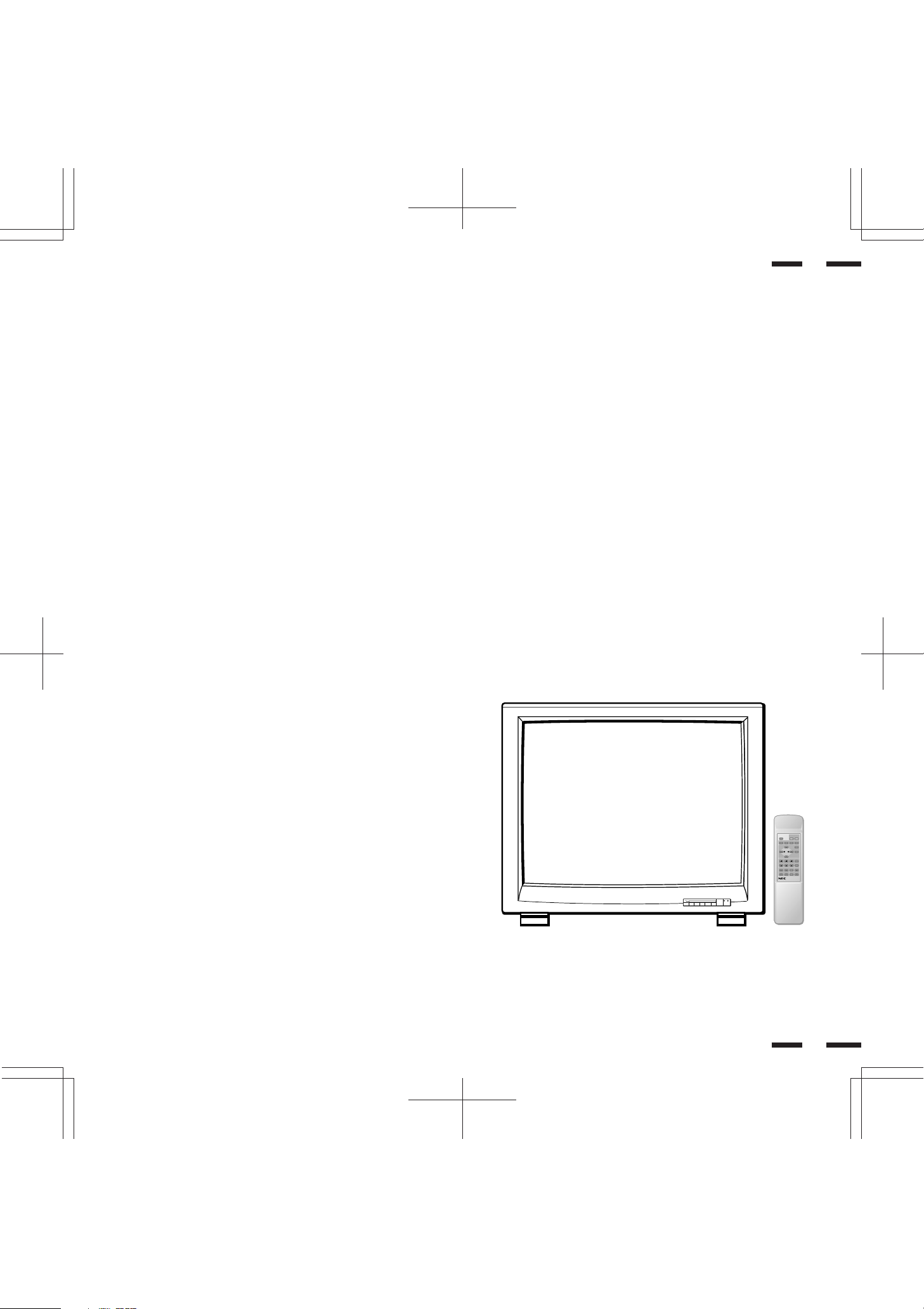
Introduction to the MultiSync XP37 Xtra/XM37 Xtra
Monitor
This section introduces you to your new MultiSync XP37 Xtra/XM37 Xtra
monitor, provides a list of materials that comes with your monitor and
describes the features and controls.
The features you’ll enjoy include:
•Simple controls
Let you make all necessary adjustments and selections with one
button simplicity from the remote control.
•37” CRT(36” viewable image size)
• True displayable 1024 x768 resolution
1
• Flexible inputs
Connect up to four different inputs at once and switch among them
with a touch of a button to seamlessly integrate information from a
computer and VCR into one presentation.
• Signal loop-through
Lets you run up to 2 monitors from one source, which can greatly
simplify connections and reduce hardware requirements.
• Attractive cabinets
A sleek, sophisticated cabinet design complements your presentation
environment and enhances the professionalism of your presentations.
• Microsoft Plug and Play compatibility
The monitor includes this standard that automatically optimizes display
settings:
Supports most IBM VGA, S-VGA, XGA, Macintosh or any other RGB
signals within a horizontal frequency range or 15.75/31 to 100 kHz
(15.75/31 to 70 kHz for XM37 Xtra) and a vertical frequency range of 45
to 120 Hz. This includes NTSC, PAL, SECAM, and M-NTSC standard video
signals.
• The supplied RGB cable allows hook up to IBM-PC compatible.
(For Macintosh, use the supplied pin adapter.)
• The analog BNC RGB terminals accept component signal.
• Front bezel controls
• Universal power supply from 100Vac to 120Vac and 220Vac to
240Vac.
Contents of the Package
The following lists all of the items included in your MultiSync multimedia
monitor package. Please save the original box and packing materials
for future transportation or shipment of this monitor.
1. MultiSync XP37 Xtra (XP-3791)/XM37 Xtra (XM-3761) multimedia
monitor
2. Power cord
3. Wireless remote control unit and two AA batteries
4. RGB cable (15-Pin Mini D-Sub To 15-pin Mini D-Sub Connector)
5. Pin adapter for Macintosh
6. User' s manual
7. Quick set up card
8. Registration card : Please fill out and return the registration card as
soon as possible.
PROCEED VIDEO 1
VIDEO 2 RGB 1 RGB 2
▼▼
+
EXIT
−
POWER
/STANDBY
2
6

79644641
POWER
ON
RGB 2RGB 1VIDEO 2VIDEO 1
POSITION/CONTROL PROCEED
EXIT
SCAN
NORMALSIDE PINHEIGHTWIDTH
BRIGHT
CONTRAST
MUTE
NORMAL
VOLUME
OFFDEGAUSS
MULTIMEDIA MONITOR
RD-346E
VIDEO 1 VIDEO 2 RGB AUDIO RGB 1
REMOTE
EXTERNAL CONTROL
DIP SW
AC IN
SPEAKER SELECT
EXT SPEAKER
RGB 2
AUDIO AUDIO
HIGH 75Ω
R
MONO
IN
THROUGH
OUT
IN
THROUGH
OUT
THROUGH
OUT
IN
BNC S
HIGH 75Ω
THROUGH
OUT
IN
R
THROUGH
OUT
IN
R
THROUGH
OUT
IN
BNC S
HIGH 75Ω
IN
THROUGH
OUT
R/CR/PRG/Y/Y B/VB/PBH/CS V
HIGH 75ΩHIGH 75Ω
SPEAKRES MUST
HAVE MORE THAN
5WATT RATING
INPEDANCE 8 OHM
RIGHT LEFT
INT EXT
IN
OUT
12345678
ON
()
L
MONO
()
L
MONO
()
L
MONO
()
L
Part Names and Functions
3
Front View
PROCEED VIDEO 1
EXIT
89
7
VIDEO 2 RGB 1 RGB 2/DTV
▼
▼
+
−
4321
56
PROCEED VIDEO 1
VIDEO 2 RGB 1 RGB 2
▼▼
+
EXIT
−
POWER
/STANDBY
POWER
/STANDBY
Rear View
0
Terminal Board
1 POWER ..................... Press to turn the main power on and off
when the AC power is supplied.
2
POWER/STANDBY
....
When this indicator is green, the monitor is
on; when the indicator is red, it is in standby.
Remote Sensor Window...
3
Receives infrared signal from the handheld
remote control.
4 RGB 2/DTV/+ ............. Press to select an RGB video source that is
connected to the RGB 2 input terminals
(BNC type). When you are in the OSM
mode, this button works as the plus button.
5 RGB 1/- ...................... Press to select an RGB video source that is
connected to the RGB 1 input terminal (DSUB 15 pin type).
When you are in the OSM mode, this button
works as the minus button.
6 VIDEO 2/ ................. Press to select an NTSC, PAL, SECAM or
M-NTSC compatible video source that is
connected to the VIDEO 2 input terminal
(BNC type or S-VIDEO 2 IN). When you are
in the OSM mode, this button works as the up
button.
NOTE: S-VIDEO IN terminals will take
preference over VIDEO IN terminals when
the video source is connected to each
terminal and VIDEO 1 or 2 selected.
7 VIDEO 1/
................. Press to select an NTSC, PAL, SECAM or M-
NTSC compatible video source that is
connected to the VIDEO 1 input terminal
(BNC type or S-VIDEO 1 IN). When you are in
the OSM mode, this button works as the
down button.
8 EXIT ........................... Press to exit the OSM mode. The OSM
screen disappears.
9 PROCEED .................Press to access OSM. The OSM screen is
displayed.
0
Remote Control Holder.....
Place remote control unit here when not in
use.
4
7
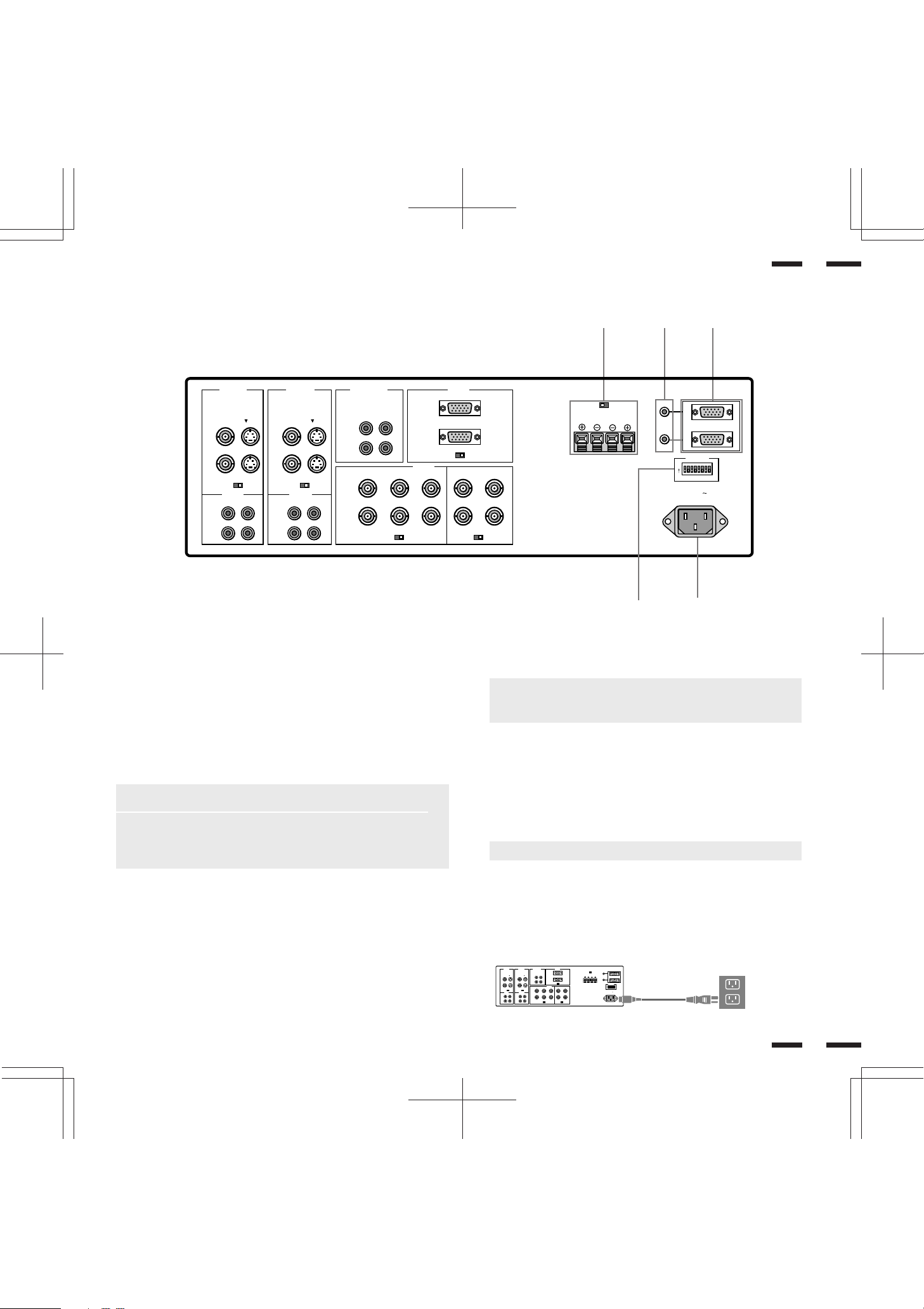
Terminal Board
VIDEO 1 VIDEO 2 RGB AUDIO RGB 1
REMOTE
PC/EXT CTL
DIP SW
AC IN
SPEAKER SELECT
EXT SPEAKER
RGB 2
AUDIO AUDIO
HIGH 75Ω
R
MONO
IN
THROUGH
OUT
IN
THROUGH
OUT
THROUGH
OUT
IN
BNC S
HIGH 75Ω
THROUGH
OUT
IN
R
THROUGH
OUT
IN
R
THROUGH
OUT
IN
BNC S
HIGH 75Ω
IN
THROUGH
OUT
R/CR/PRG/Y/Y B/CB/PBH/CS V
HIGH 75ΩHIGH 75Ω
SPEAKRES MUST
HAVE MORE THAN
5WATT RATING
INPEDANCE 8 OHM
RIGHT LEFT
INT EXT
IN
OUT
12345678
ON
()
L
MONO
()
L
MONO
()
L
5
VIDEO 1 VIDEO 2 RGB AUDIO RGB 1
()
R
MONO
BNC S
IN
THROUGH
OUT
HIGH 75Ω
AUDIO AUDIO
()
MONO
L
R
IN
THROUGH
OUT
IN
THROUGH
OUT
IN
THROUGH
OUT
BNC S
HIGH 75Ω
()
MONO
L
R
L
IN
THROUGH
OUT
R/CR/PRG/Y/Y B/CB/PBH/CS V
IN
THROUGH
OUT
A PC/ECT CTL IN (D-Sub 15-pin)
This terminal is used when power ON/OFF, input selection, AUDIO
MUTE, PICTURE MUTE, and DEGAUSS are operated externally
(by external control). See also page 42 for external control port pin
assignments. You can also use this connector to connect your PC to
control the MultiSync XP37 Xtra/XM37 Xtra monitor. This allows you
to utilize your PC and serial communication protocol to control the
monitor.
NOTE: Select EXT. CONTROL ON by setting pin No. 6 of DIP SW
to the ON position when operating the monitor by external control.
NOTE: When in the EXT. CONTROL mode, the following
operations of the supplied wireless remote control are not possible:
Power control ON/ OFF, Input selection, and Degauss switch ON/
OFF.
PC/ECT CTL OUT (D-Sub 15-pin).....Connect to a second monitor’s
EXTERNAL CONTROL input to relay the signal input at the
EXTERNAL CONTROL IN. The EXTERNAL CONTROL OUT
terminal is used to connect several monitors together and allows
all of the monitors to be controlled by one external control. No. 6
pin (EXT. CONTROL) of DIP SW must be set to the ON position on
all of the monitors.
B REMOTE IN/OUT
Connect the optional remote cable, included with the optional
remote control, to the REMOTE IN terminal. The REMOTE OUT
terminal is used to connect several monitors together and allows all
of the monitors to be controlled by one remote control.
IN
THROUGH
OUT
RGB 2
HIGH 75Ω
HIGH 75ΩHIGH 75Ω
C EXT SPEAKER
D DIP Switch
E AC Input
SPEAKRES MUST
HAVE MORE THAN
5WATT RATING
INPEDANCE 8 OHM
C
SPEAKER SELECT
INT EXT
EXT SPEAKER
RIGHT LEFT
BA
REMOTE
IN
OUT
ON
PC/EXT CTL
DIP SW
12345678
AC IN
D
E
NOTE: Up to 50 monitors can be connected in the serial
connection. (This can be done only when the optional
supplied remoto cable is used.)
RIGHT + ....... Connect RIGHT speaker positive wire here.
RIGHT - ........ Connect RIGHT speaker negative wire here.
LEFT - .......... Connect LEFT speaker negative wire here.
LEFT + ......... Connect LEFT speaker positive wire here.
SPEAKER SELECT INT/EXT Select Switch.....Set to the INT
position for built-in monitor speakers. Set to the EXT position
for speakers connected to the EXT SPEAKER terminals.
NOTE: The speaker cables must be less than 3m in length.
DIP SW..... This DIP switch sets Sync. Control, the Intelligent
Power Manager, external control on/off, remote control on/off,
and OSM system control on/off. See pages 17 and 18 for more
details.
Connect the supplied power cord’ s three-pin plug here.
Insert the prongs completely.
6
8
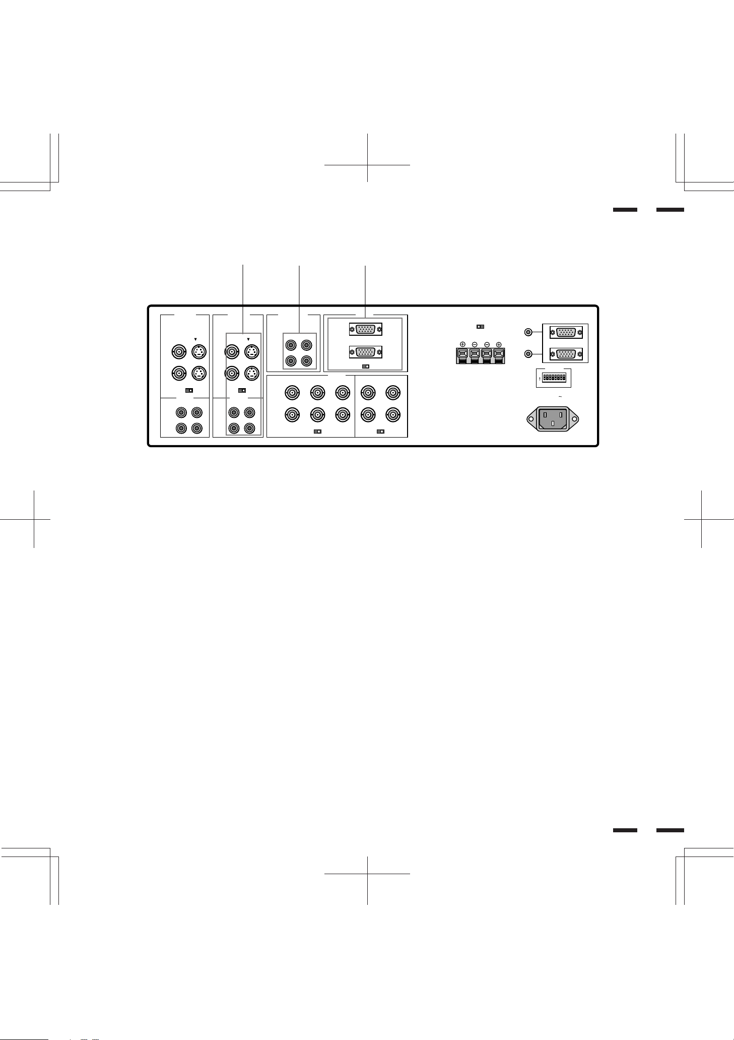
Terminal Board
7
H
VIDEO 1 VIDEO 2 RGB AUDIO RGB 1
BNC S
IN
THROUGH
OUT
HIGH 75Ω
AUDIO AUDIO
()
MONO
L
R
IN
THROUGH
OUT
IN
THROUGH
OUT
IN
THROUGH
OUT
BNC S
HIGH 75Ω
()
MONO
L
R
G
()
R
MONO
L
IN
THROUGH
OUT
R/CR/PRG/Y/Y B/CB/PBH/CS V
IN
THROUGH
OUT
F RGB 1 (Mini D-SUB 15 pin)
RGB Input/Throughout.....Attach either end of the RGB Cable to a
computer, and then attach the other end to Input terminal. You can
then use Throught out terminal, if you wish, to output the computer
signal to a monitor. (If you do use a second monitor, turn the
monitor switch to “on.”)
75 Ω/HIGH Impedance Select Switch.....This switch should be “75Ω”
for normal use without external termination or when your RGB
signal should be terminated with 75Ω. Switch to the “HIGH”
position when you have another monitor attached to your RGB
through-put connector.
G RGB AUDIO
AUDIO R IN.....This is where you connect RGB right audio output
from a computer or another RGB source.
AUDIO L(MONO)IN.....This is where you connect RGB left audio
output from a computer or another RGB source.
AUDIO R THROUGH OUT.....Connect to a second monitor’ s
RGB right audio input.
AUDIO L THROUGH OUT.....Connect to a second monitor’s
RGB left audio input.
IN
THROUGH
OUT
RGB 2
F
HIGH 75Ω
HIGH 75ΩHIGH 75Ω
SPEAKRES MUST
HAVE MORE THAN
5WATT RATING
INPEDANCE 8 OHM
SPEAKER SELECT
INT EXT
EXT SPEAKER
RIGHT LEFT
REMOTE
IN
OUT
ON
PC/EXT CTL
DIP SW
12345678
AC IN
H VIDEO 2
VIDEO 2 IN (BNC type).....Connect another VCR or laser disk player
here to display the video.
S-VIDEO 2 IN.....Connect S-Video input from another external
source like a VCR.
THROUGH OUT (BNC type).....Connect to a second monitor’ s video
input to relay the video signal input at VIDEO 2 IN.
THROUGH OUT (S-VIDEO).....Connect to a second monitor’ s S-
connector input to relay the video signal input at S-VIDEO 2 IN.
75 Ω/HIGH Impedance Select Switch for BNC type.....Set to “75 Ω”
during normal operation. In multiple connections using VIDEO 2
IN and THROUGH OUT (BNC type) terminals, set to “HIGH” on all
but the last monitor. Set to “75 Ω” on the last monitor only.
AUDIO R IN.....This is your right channel audio input for stereo
sound.
AUDIO L IN (MONO).....This is your left channel audio input for
stereo sound coming from video equipment or audio system. It
also serves as the mono audio input.
AUDIO R THROUGH OUT.....Connect to a second monitor’ s right
channel audio input.
AUDIO L THROUGH OUT.....Connect to a second monitor’ s left
channel audio input.
8
9
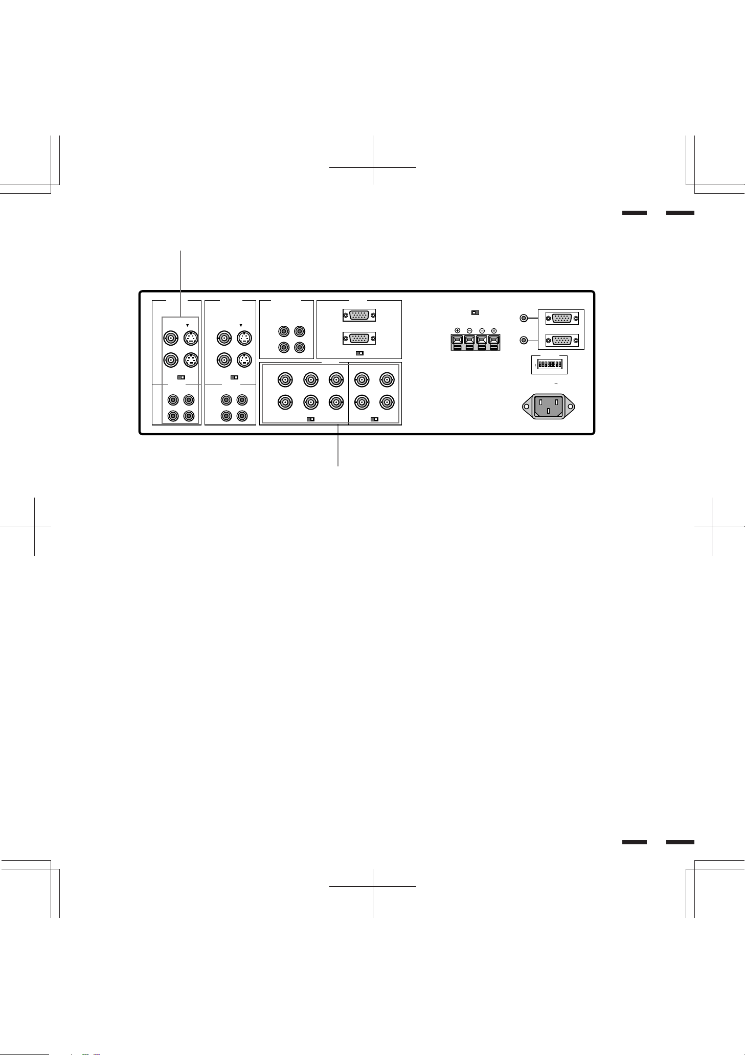
Terminal Board
9
I
VIDEO 1 VIDEO 2 RGB AUDIO RGB 1
IN
THROUGH
OUT
RGB 2
BNC S
IN
THROUGH
OUT
HIGH 75Ω
AUDIO AUDIO
()
MONO
L
R
IN
THROUGH
OUT
IN
THROUGH
OUT
IN
THROUGH
OUT
BNC S
HIGH 75Ω
()
MONO
L
R
()
R
MONO
L
IN
THROUGH
OUT
R/CR/PRG/Y/Y B/CB/PBH/CS V
IN
THROUGH
OUT
I VIDEO 1
VIDEO 1 IN (BNC type).....Connect a VCR or laser disk player here
to display the video.
S-VIDEO 1 IN.....Here is where you connect S-Video input from an
external source like a VCR.
THROUGH OUT (BNC type).....Connect to a second monitor’ s video
input to relay the video signal input at VIDEO 1 IN.
THROUGH OUT (S-VIDEO).....Connect to a second monitor’ s S-
connector input to relay the video signal input at S-VIDEO 1 IN.
75 Ω/HIGH Impedance Select Switch for BNC type.....Set to “75 Ω”
during normal operation. In multiple connections using VIDEO 1
IN and THROUGH OUT (BNC type) terminals, set to “HIGH” on
all but the last monitor. Set to “75 Ω” on the last monitor only.
AUDIO R IN.....This is your right channel audio input for stereo
sound.
AUDIO L IN (MONO).....This is your left channel audio input for
stereo sound coming from video equipment or audio system. It
also serves as the mono audio input.
AUDIO R THROUGH OUT.....Connect to a second monitor’ s right
channel audio input.
AUDIO L THROUGH OUT.....Connect to a second monitor’ s left
channel audio input.
J
HIGH 75Ω
HIGH 75ΩHIGH 75Ω
SPEAKRES MUST
HAVE MORE THAN
5WATT RATING
INPEDANCE 8 OHM
SPEAKER SELECT
INT EXT
EXT SPEAKER
RIGHT LEFT
REMOTE
IN
OUT
ON
PC/EXT CTL
DIP SW
12345678
AC IN
J RGB 2
R/C
R/PR,G/Y/Y,B/CB/PB, H/CS and V IN (BNC).....These are analog
RGB input terminals.
Connect external components with R, G, B, H/CS, and V output
terminals to these analog RGB input terminals. Be sure that the
RGB connection cable is correctly attached to the corresponding
terminals.
R/C
R/PR,G/Y/Y,B/CB/PB, H/CS and V THROUGH OUT (BNC).....Connect
to a second monitor’s RGB inputs to relay the RGB signal inputs at
R, G, B, H/CS, and V IN.
75 Ω/HIGH Impedance Select Switches for RGB and H/CS&V.....Set to
“75 Ω” during normal operation. In multiple connections using R,
G, B, H/CS and V IN and OUT terminals, set to “HIGH” on all but
the last monitor. Set to “75 Ω” on the last monitor only.
10
10

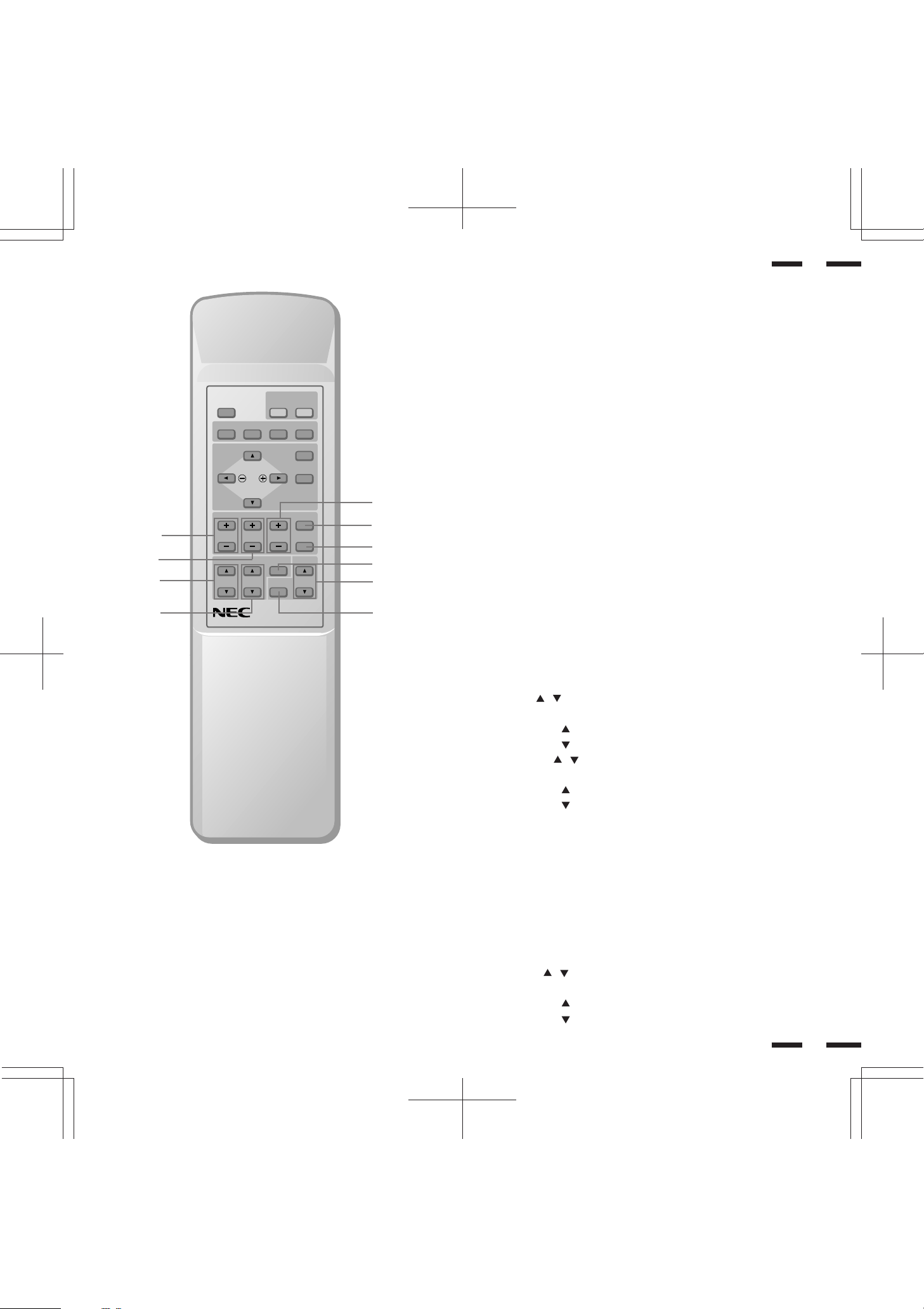
Remote Control Unit
2
POSITION/ CONTROL PROCEED
4
BRIGHT
CONTRAST
MULTIMEDIA MONITOR
RD-346E
POWER
OFFDEGAUSS
NORMAL
MUTE
ON
RGB 2RGB 1VIDEO 2VIDEO 1
EXIT
SCAN
NORMALSIDE PINHEIGHTWIDTH
VOLUME
79644641
1
3
5
6
11
NOTE: When not in use the remote control unit is conveniently stowed in the
holder on the rear panel.
1 POWER ON/OFF
Press POWER ON to turn the monitor on when the POWER/STANDBY
indicator is lit amber.
Press POWER OFF to turn the monitor off and the monitor will go into the
standby condition.
2 DEGAUSS
Press to demagnetize the picture tube in the manual operation. See also
page 27.
3 Input Select
VIDEO 1 ..... Press to select an NTSC, PAL, SECAM or M-NTSC
compatible video source from a VCR, laser disc player, document camera,
or an S-Video source from a VCR connected to the VIDEO 1 IN terminal.
VIDEO 2 ..... Press to select an NTSC, PAL, SECAM or M-NTSC
compatible video source from a VCR, laser disc player, document camera,
or an S-Video source from a VCR connected to the VIDEO 2 IN terminal.
RGB 1 ....... Press to select an RGB video source from a computer
connected to the RGB 1 IN terminal.
RGB 2 ....... Press to select an RGB/component video source from a
computer, NEC scan converter or YPBPR/YCBCR Signal source connected
to the RGB 2 IN terminal.
OSM Control
4 POSITION/CONTROL
POSITION( ) ...... Adjusts the vertical position of the image up and
down, and the horizontal position of the image from left to right.
CONTROL ( + / - ) ..... Moves the bar in the + or - direction to increase or
decrease the adjustment in an OSM menu.
CONTROL( / )..Select one of the controls in an OSM menu. Press to
select a higher item in the menu; press to select a lower item in the menu.
5 PROCEED
Press to access OSM. When an adjustment item is selected, a press of this
button returns to its icon selection screen.
6 EXIT
Press to exit the OSM mode.
NOTE: The direct keys such as BRIGHT, CONTRAST, WIDTH, HEIGHT,
SIDE PIN can access each control while in the OSM mode.
12
11
7
8
B
POWER
ON
OFFDEGAUSS
RGB 2RGB 1VIDEO 2VIDEO 1
POSITION/ CONTROL PROCEED
EXIT
SCAN
NORMALSIDE PINHEIGHTWIDTH
NORMAL
BRIGHT
CONTRAST
MUTE
VOLUME
9
0
A
D
F
13
Raster Control
7 WIDTH (+ / -)
Adjusts the horizontal size of the image.
8 HEIGHT (+ / -)
Adjusts the vertical size of the image.
9 SIDE PIN (+ / -)
Adjusts the curvature of the edges of the left and right side of the display
image either inward or outward. The image should be adjusted to attain a
straight line on the left and right sides.
0 SCAN SELECT
Each time this key is pressed, the picture size switches from OVER SCAN
for large size to UNDER SCAN for small size and vice versa. Normally select
OVER SCAN for video display and UNDER SCAN for RGB display.
A NORMAL
This key resets the raster adjustment settings of user changeable memory
and recalls the factory preset data.
C
MULTIMEDIA MONITOR
RD-346E
79644641
E
Visual Control
B BRIGHT ( / )
Adjusts the overall image and screen brightness.
Press and hold for a brighter picture.
Press and hold for a darker picture.
C CONTRAST ( / )
Adjusts the image brightness in relation to the background.
Press and hold for higher contrast.
Press and hold for lower contrast.
NOTE: The VISUAL CONTROL storing operation is effective only for the
input currently used (VIDEO1, VIDEO 2, RGB 1 or RGB 2).
D NORMAL
This key resets the visual control settings and recalls the factory preset data.
NOTE: The brightness and contrast adjustment level are factory preset at
the optimum position.
E MUTE
Press to cancel sound ; press again to restore sound.
NOTE: The other ways to restore sound are to press POWER OFF, then
ON or to press VOLUME keys on the remote control unit.
F VOLUME ( / )
Adjusts the volume.
Press and hold to increase sound.
Press and hold to decrease sound.
14
12
 Loading...