


NEC UPC8109TB, UPC8109TB-E3, UPC8109T-E3, UPC8109T, UPC8106TB-E3 Datasheet
...
DATA SHEET
BIPOLAR ANALOG INTEGRATED CI RCUITS
µµµµ
PC8106TB,
µµµµ
PC8109TB
SILICON MMIC 2.0 GHz FREQUENCY UP-CONVERTER
FOR CELLULAR/CORDLESS TELEPHONES
DESCRIPTION
The µPC8106TB and µPC8109TB are silicon monolithic integrated circuit designed as frequency up-converter for
cellular/cordless telephone transmitter stage. The µPC8106TB features improved intermodulation and µPC8109TB
features low current consumption. From these two version, you can chose either IC corresponding to your system
design. These TB suffix ICs which are smaller package than conventional T suffix ICs contribute to reduce your
system size.
The µPC8106TB and µPC8109TB are manufactured using NEC’s 20 GHz fT NESATTMIII silicon bipolar process.
This process uses a silicon nitride passivation film and gold electrodes. These materials can protect chip surface
from external pollution and prevent corrosion/migration. Thus, this IC has excellent performance, uniformity and
reliability.
FEATURES
• Recommended operating frequency : f
• Supply voltage : VCC = 2.7 to 5.5 V
• High-density surface mounting : 6-pin super minimold package
• Low current consumption : ICC = 9 mA TYP. @ µPC8106TB
• Minimized carrier leakage : Due to double balanced mixer
• Built-in power save function
RFout
= 0.4 GHz to 2.0 GHz, f
ICC = 5 mA TYP. @ µPC8109TB
IFin
= 100 MHz to 400 MHz
APPLICATION
• Cellular/cordless telephone up to 2.0 GHz MAX (example: PHS, PDC, DCS1800 and so on)
ORDERING INFORMATION
Part Number Markings Product Type Package Supplying Form
µ
PC8106TB-E3 C2D High IP
µ
PC8109TB-E3 C2G Low current consumption
Remark
Document No. P12770EJ2V0DS00 (2nd edition)
Date Published April 1999 N CP(K)
Printed in Japan
To order evaluation samples, please contact your local NEC sales office.
(Part number for sample order:
The information in this document is subject to change without notice. Before using this document, please
confirm that this is the latest version.
Not all devices/types available in every country. Please check with local NEC representative for
availability and additional information.
3
PC8106TB, µPC8109TB)
µ
Caution Electro-static sensitive devices
6-pin super
minimold
Embossed tape 8 mm wide.
Pin 1, 2, 3 face to tape perf oration side.
QTY 3 kp/Reel.
1997, 1999©
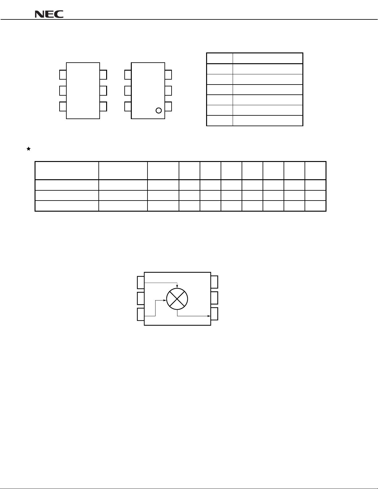
PIN CONNECTIONS
3
2
1
4
5
6
(Top view)
Marking is an example of PC8106TB.
4
5
6
3
2
1
(Bottom view)
C 2 D
µ
µµµµ
PC8106TB,
Pin No. Pin Name
1 IFinput
2GND
3 LOinput
4PS
5V
6 RFoutput
CC
µµµµ
PC8109TB
SERIES PRODUCTS (TA = +25
TYPE PRODUCT NAME VCC (V)
3
High IP
Low power consumption
Higher IP
3
PC8106TB 2.7 to 5.5 9 9 7
µ
PC8109TB 2.7 to 5.5 5 6 4
µ
PC8163TB 2.7 to 3. 3 16.5 9 5.5 0.5 –2 +9.5 +6
µ
C, VCC = VPS = V
°°°°
RFout
= 3.0 V, ZL = ZS = 50
CC
I
(mA)
CG1
(dB)
CG2
(dB)
)
ΩΩΩΩ
O(sat)
P
(dBm)
2
−
5.5
−
O(sat)
1
P
2
(dBm)
4 +5.5 +2.0
−
7.5 +1.5
−
OIP31
(dBm)
Caution The above table lists the typical performance of each model. See ELECTRICAL CHARACTER-
ISTICS for the test conditions.
BLOCK DIAGRAM (FOR THE
PC8106TB AND
µµµµ
LO input
GND
IF input
µµµµ
(Top view)
PC8109TB)
PS
CC
V
RF output
OIP32
(dBm)
1.0
−
2
Data Sheet P12770EJ2V0DS00
µµµµ
PC8106TB,
µµµµ
PC8109TB
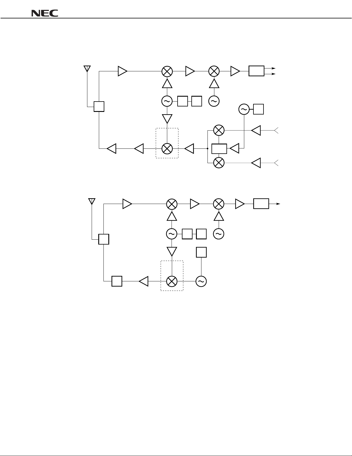
SYSTEM APPLICATION EXAMPLES (SCHEMATICS OF IC LOCATION IN THE SYSTEMS)
PHS, DECT
RX
SW
TX
PA
Analog cellular telephone
RX
SW
VCO
PC8106TB
µ
VCO
÷N PLL
÷N PLL
0°
Phase
shifter
90°
DEMO.
PLL
FM
DEMO.
I
Q
I
Q
TX
PA
PC8109TB
µ
PLL
MOD.
Data Sheet P12770EJ2V0DS00
3

µµµµ
PC8106TB,
µµµµ
PC8109TB
PIN FUNCTIONS (FOR THE
Pin
No.
Pin
Name
1 IFinput
2GND 0
3 LOinput
5VCC2.7 to 5.5
6 RFoutput Same bias
4PSVCC/GND
Applied
Voltage
(V)
−
−
CC
as V
through
external
inductor
Pin
Voltage
(V)
1.3 This pin is IF input to double bal anc ed
−
2.4 Local input pin. Recommendable input
−
−
−
PC8106TB AND
µµµµ
Note
Function and Explanation Equivalent Circuit
mixer (DBM). The input is des i gned as
high impedance. The circuit contributes to suppress spurious signal.
Also this symmetrical circuit c an keep
specified performance insensitive to
process-condition distribution. For
above reason, double balanced mixer
is adopted.
GND pin. Ground pattern on the board
should be formed as wide as poss i bl e.
Track Length should be kept as short
as possible to minimi ze ground
impedance.
level is −10 to 0 dBm.
Supply voltage pin.
This pin is RF output from DB M . This
pin is designed as open collec tor. Due
to the high impedance output, this pin
should be externally equipped wit h LC
matching circuit t o next stage.
Power save control pin. B i as controls
operation as follows.
PC8109TB)
µµµµ
5
6
3
1
2
VCC
5
Each pin voltage is measured with V
Note
Pin bias Cont rol
CC
V
GND Power Save
CC
= V
PS
= V
Operation
RFout
= 3.0 V.
GND
4
2
4
Data Sheet P12770EJ2V0DS00
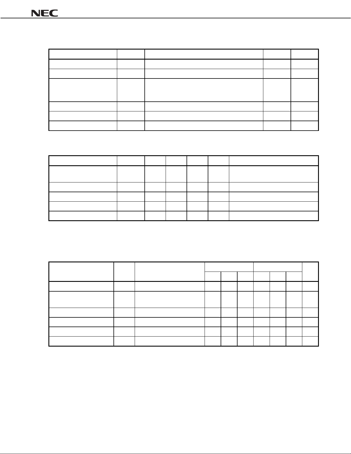
ABSOLUTE MAXIMUM RATINGS
Parameter Symbol Test Conditions Rating Unit
µµµµ
PC8106TB,
µµµµ
PC8109TB
Supply Votage V
PS pin Input Voltage V
Power Dissipation of
Package
Operating Ambient Temperature T
Storage Temperature T
Maximum Input Power P
CC
PS
P
TA = +25 °C, Pin 5 and 6 6.0 V
TA = +25 °C 6.0 V
D
Mounted on double-sided copper-clad 50 × 50
1.6 mm epoxy glass P WB
A
T
= +85 °C
A
stg
in
RECOMMENDED OPERATING CONDITIONS
Parameter Symbol MIN. TYP. MAX. Unit Note
Supply Voltage V
Operating Ambient Temperature T
Local Input Level P
RF Output Frequency f
IF Input Frequency f
CC
LOin
RFout
IFin
2.7 3.0 5.5 V The same voltage should be supplied t o
A
40 +25 +85 °C
−
10
−
0.4
100
×
pin 5 and 6
S
50dBmZ
−
−
−
2.0 GHz With external m atching circuit
400 MHz
= 50 Ω (without matching)
200 mW
40 to +85 °C
−
55 to +150 °C
−
+10 dBm
ELECTRICAL CHARACTERISTICS
A
= +25 °C, VCC = V
(T
RFout
= 3.0 V, f
specified)
Parameter Symbol Conditions
Circuit Current I
Circuit Current in Power-
save Mode
Conversion Gain 1 CG1 f
Conversion Gain 2 CG2 f
Maximum RF Output Power 1 P
Maximum RF Output Power 2 P
CC
ICC(PS) VPS = 0 V
O(sat)
1f
O(sat)
2f
IFin
= 240 MHz, P
LOin
=
5 dBm, and VPS
−−−−
PC8106TB
µ
2.7 V unless otherwise
≥≥≥≥
PC8109TB
µ
Unit
MIN. TYP. MAX. MIN. TYP. MAX.
No signal 4.5 9 13.5 2.5 5 8.0 mA
RFout
= 0.9 GHz, P
RFout
= 1.9 GHz, P
RFout
= 0.9 GHz, P
RFout
= 1.9 GHz, P
−−
IFin
= −30 dBm 6 9 12 3 6 9 dB
IFin
= −30 dBm 4 7 10 1 4 7 dB
IFin
= 0 dBm
IFin
= 0 dBm
4
−
6.5
−
10
2
−
4
−
−−
7.5−5.5
−−
−−10−
7.5
10
µ
dBm
−
dBm
−
A
Data Sheet P12770EJ2V0DS00
5

OTHER CHARACTERISTICS, FOR REFERENCE PURPOSES ONLY
A
= +25 °C, VCC = V
(T
RFout
= 3.0 V, P
LOin
=
5 dBm, and VPS
−−−−
2.7 V unless otherwise mentioned)
≥≥≥≥
µµµµ
PC8106TB,
µµµµ
PC8109TB
Parameter Symbol Conditions
OIP31f
Intercept Point
Third-Order Intermodulation
Distortion 1
Third-Order Intermodulation
Distortion 2
SSB Noise Figure SSBNF f
Rise time T
Response Time
Fall time T
3
2f
OIP
IM31f
IM32
PS(rise)
PS(fall)
Reference Value
PC8106TBµPC8109TB
µ
IFin1
= 240.0 MHz f
IFin2
= 240.4 MHz f
IFint
= 240.0 MHz
f
IFin2
= 240.4 MHz
f
IFin
= −20 dBm
P
RFout
= 0.9 GHz, f
VPS: GND → V
VPS: VCC → GND 2.0 2.0
RFout
= 0.9 GHz +5.5 +1.5 dBmOutput Third-Order Distortion
RFout
= 1.9 GHz +2.0
RFout
= 0.9 GHz
RFout
f
= 1.9 GHz
IFin
= 240 MHz 8.5 8.5 dB
CC
31
−
30
−
2.0 2.0
1.0
−
−
−
29 dBc
28 dBc
Unit
µ
µ
APPLICATION CIRCUIT EXAMPLE CHARACTERSISTICS FOR REFERENCE PURPOSE ONLY
A
= +25 °C, VCC = VPS = V
(T
Parameter Symbol Conditions
Conversion Gain CG f
Maximum RF Output Power P
RFout
= 3.0 V, f
O(sat)
IFin
= 130 MHz, f
RFout
= 1.5 GHz, with applicati on circuit
example
RFout
f
= 1.5 GHz, with applicati on circuit
example
LOin
= 1630 MHz, P
LOin
=
5 dBm)
−−−−
Reference Value
PC8106TB
µ
7dB
3.5 dBm
−
Unit
sPower Save
s
6
Data Sheet P12770EJ2V0DS00

µµµµ
PC8106TB,
µµµµ
PC8109TB
TEST CIRCUIT 1 (RF = 900 MHz, for the
RF = 900 MHz, matched
Spectrum Analyzer
50 Ω
10 000
pF
V
CC
C
4
1000 pF 1 pF
C
5
C
6
C
3
1 000 pF
PC8106TB and
µµµµ
6
L
6.8 nH
*
RFoutputPSIFinput
5
CC
V
4
PC8109TB)
µµµµ
GND
LOinput
Signal Generator
100 pF
1
C
2
3
1
100 pF
C
2
50 Ω
Signal Generator
50 Ω
P
Loin
= –5 dBm
* In case of unstable operation, please connect capacitor 100 pF between 4 pin and 5 pin and adjust the matching
circuit.
EXAMPLE OF TEST CIRCUIT 1 ASSEMBLED ON EVALUATION BOARD
RF Connector →
RFOUT
1 000 pF
C
6
C
3
1 000 pF
6.8 nH
1 pF
L
5
C
1
IFIN
100 pF
C
1
P/S
1 000 pF
PC8106TB
µ
C
4
10 000 pF
LO
100 pF
C
2
IN
Data Sheet P12770EJ2V0DS00
7

COMPONENT LIST
Form Symbol Value
Chip capacitor
Through capacitor C
Chip inductor L
6.8 nH: Murata Mfg. Co., Ltd. LQP31A6N8J04
Note
Notes on the board
35 × 42 × 0.4 mm polyimide board, 35
1.
Ground pattern on rear of the board
2.
Solder plated patterns
3.
4.
5.
: Through holes
C6 is for RF short on the board pattern
C1, C
C3, C
C
µµµµ
PC8106TB,
2
6
5
4
100 pF
1 000 pF
1 pF
10 000 pF
Note
6.8 nH
m double-sided copper clad
µ
µµµµ
PC8109TB
8
Data Sheet P12770EJ2V0DS00
 Loading...