


 Loading...
REAKTOR 5
Instrument Guide

The information in this document is subject to change without notice and does not represent a commitment on the part of Native Instruments Software Synthesis GmbH. The software described by this document is subject to a License Agreement and may not be copied to other media. No part of this publication may be copied, reproduced or otherwise transmitted or recorded, for any purpose, without prior written permission by Native Instruments Software Synthesis GmbH. All product and company names are trademarks of their respective owners.
Library credits
Concept + Production: Mate Galic
Technical Assistance: |
Cornelius Lejeune, Jeremiah Savage |
Documentation: |
Cornelius Lejeune, James Walker-Hall, |
|
Thomas Loop, Jace Clayton |
Instrument Design: |
Mike Daliot, Lazyfish, James Walker-Hall, |
|
Martijn Zwartjes, Programchild, Tim Exile |
Sounddesign: |
Dennis DeSantis, Junkie XL, AME, Jörg Remmer-Müller, |
|
Speedy J, Smyglyssna, Richard Devine, Jam El Mar, |
|
Simon Pyke, Tim Exile, Frank Martiniq, Rob Acid, |
|
Jake Mandell, Martijn Zwartjes, Jaap Wajer, |
|
Telefon Tel Aviv, Mike Dalio, Programchildt |
Interface Design: |
Pfadfinderei, Phillipp Granzin, Ian Warner, |
|
Leonard Lass, Phillip Roller, Studiotonne, |
|
Johannes Schardt |
©Native Instruments Software Synthesis GmbH, 2005. All rights reserved. First Edition, May 2005
REAKTOR is a trademark of Native Instruments Software Synthesis.
Germany |
USA |
Native Instruments GmbH |
Native Instruments USA, Inc. |
Schlesische Str. 28 |
5631 A Hollywood Boulevard |
D-10997 Berlin |
Los Angeles, CA 90028 |
Germany |
USA |
info@native-instruments.de |
info@native-instruments.com |
www.native-instruments.de |
www.native-instruments.com |
Table of Contents |
|
Synthesizer................................................................................................. |
5 |
Carbon 2........................................................................................ |
5 |
Oki Computer 2 ............................................................................. |
16 |
SteamPipe 2 ................................................................................ |
23 |
SubHarmonic................................................................................ |
32 |
Grooveboxes ............................................................................................. |
37 |
Aerobic ......................................................................................... |
37 |
Massive........................................................................................ |
43 |
Newscool ..................................................................................... |
53 |
Sinebeats 2.................................................................................. |
58 |
Sound Generators...................................................................................... |
66 |
Skrewell....................................................................................... |
66 |
SpaceDrone.................................................................................. |
69 |
Sample Player........................................................................................... |
72 |
BeatSlicer 2 .................................................................................. |
72 |
Memory Drum 2............................................................................ |
78 |
Sample Transformer .................................................................................. |
85 |
L3............................................................................................... |
85 |
Random Step Shifter ..................................................................... |
90 |
Splitter ........................................................................................ |
94 |
Vectory ........................................................................................ |
98 |
Effects.................................................................................................... |
104 |
FlatBlaster 2................................................................................ |
104 |
Lurker......................................................................................... |
107 |
Space Master 2 ........................................................................... |
114 |
Sequencer .............................................................................................. |
116 |
SQ16.......................................................................................... |
116 |
SQ8 ........................................................................................... |
118 |
SQ 8x8....................................................................................... |
120 |
SQP............................................................................................ |
122 |
REAKTOR 5 |
Table of Contents – III |
IV |
REAKTOR 5 |
Synthesizer
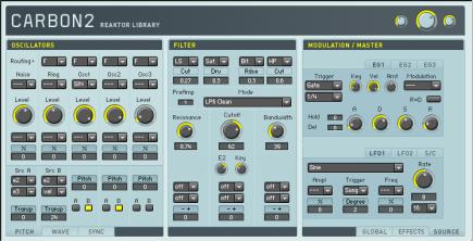
Carbon 2
Carbon2 is based on Reaktor 4’s well-known workhorse synthesizer, but it has been completely rebuilt. In particular the oscillators and filters are now based on Reaktor Core components developed particularly for this instrument. The panel has been optimized for usability, with a clear structure providing fast access to all parameters while hiding the technical complexity.
Basically, Carbon2 is a classical subtractive synthesizer. The signal of the three oscillator section (left column of the panel) passes through a multi-mode filter (middle column) and is then routed to the effect units (right column). Several modulation sources such as envelope generators and LFOs (placed in a second page in the right panel column) and the global parameters (a third page in the right column) control the sound, adding additional liveliness and movement.
Oscillators
The oscillator section produces the instrument’s basic signal. Three oscillator slots provide several different waveforms; along with traditional analogue types like sine and sawtooth there is a digital wavetable oscillator containing a wide array of waveforms that can be crossfaded smoothly. A noise generator and
REAKTOR 5 |
Carbon 2 – 5 |
a ring modulator based on the signal of the three main oscillators are added for a total of five basic sound sources.
Each oscillator slot offers control over volume, pitch, and waveform synchronization. The pitch and sync controls are placed in two pages at the bottom of the panel, grouped with a third page controlling the waveform. This third page is only active if the digital wavetable or the doubled sawtooth is selected.
Main |
Routing |
Sets the destination of the respective oscillator’s signal. On [F], |
|
|
the sound is sent to the [Filter] section; switching to [D] bypasses |
|
|
the filter and routes the signal directly to the effect units. |
|
Noise |
Switches the white noise generator on or off. |
|
Ring |
Selects which oscillator signals are fed into the ring modulator. |
|
|
Switch off to save CPU power if the ring modulator is not used. |
|
Osc1/2/3 |
Selects the waveform of each oscillator slot. Along with the stan- |
|
|
dard waveforms (sawtooth, pulse, triangular, sine and noise), you |
|
|
will find a doubled sawtooth, a quantized sine, a buzz oscillator |
|
|
based on a noise generator, and a digital wavetable. (See the |
|
|
[Wave] page for additional information on the doubled sawtooth |
|
|
and the digital wavetable.) |
|
Level |
Sets the slot’s volume level. |
|
Level Modulation |
Selects the slot’s volume level modulation source. |
|
Source |
|
|
Level Modulation |
Sets the amount and polarity of modulation applied to the slot’s |
|
Amount |
volume level. Clicking on the control’s title bar restores the value |
|
|
to its default. |
Pitch |
A/B Modulation |
Selects sources to modulate the oscillators’ pitch. The two indi- |
|
Source |
vidual slots ([A] and [B]) can mix up to two sources. |
|
A/B Modulation |
Adjusts the amount and polarity of modulation applied to the |
|
Amount |
oscillators’ pitch. The left side of the control adjusts coarse values, |
|
|
the right side is used for fine-tuning; clicking the control’s title |
|
|
bar restores the value to its default. |
|
Osc1/2/3 Pitch |
Transposes the oscillators’ sound respectively. The left side of |
|
Shift |
the control adjusts coarse values, the right side is used for fine- |
|
|
tuning; by clicking on the controls title bar with the mouse the |
|
|
value is reset to its default. |
|
Osc1/2/3 |
Turns modulation of the oscillator’s pitch by modulation slot [A] |
|
Modulation |
or [B] on or off. |
|
Switch A/B |
|
6 – Carbon 2 |
REAKTOR 5 |
Wave |
A/B Modulation |
Selects sources to modulate the waveform. The two individual |
|
Source |
slots ( [A] and [B]) can mix up to two sources. This will show no |
|
|
effect until the doubled sawtooth or the wavetable is selected |
|
|
in [Osc1/2/3]. |
|
A/B Modulation |
Adjusts the amount and polarity of modulation applied to the |
|
Amount |
waveform. Clicking on the control’s title bar resets the value to |
|
|
its default. This will show no effect until the doubled sawtooth |
|
|
or the wavetable is selected in [Osc1/2/3]. |
|
Osc1/2/3 |
This either selects a digital waveform from the wavetable, or – if |
|
Waveform |
the doubled sawtooth is activated in [Osc1/2/3] – this controls |
|
Control |
the ratio between the phases of both sawtooth waves. |
|
Osc1/2/3 |
Turns modulation of the waveform selection by modulation slot |
|
Modulation |
[A] or [B] on or off. |
|
Switch A/B |
|
Sync |
Gate Sync Switch |
Turns synchronization of the oscillators’ waveforms to the MIDI |
|
|
gate on or off. If on, all three oscillators are reset to the phase |
|
|
adjusted in [Gate Sync Phase] when a note is pressed. |
|
Gate Sync Phase |
Controls the phase to which all oscillators are set on MIDI gate |
|
|
events. Clicking on the control’s title bar restores the default |
|
|
value. |
|
Osc2/3 Sync |
Switches on or off the synchronization of the oscillators 2 and 3 |
|
Switch |
respectively to the signal of oscillator 1. If on, the oscillator is reset |
|
|
to the phase adjusted in [Osc2/3 Sync Phase] when the signal of |
|
|
oscillator 1 rises above zero. (See also [Osc2/3 Mode Fade].) |
|
Osc2/3 Sync |
Controls the phase to which the oscillators 2 and 3 are reset |
|
Phase |
when the signal of oscillator 1 rises above zero. Clicking on the |
|
|
control’s title bar restores the default value. (See also [Osc2/3 |
|
|
Mode Fade].) |
|
Osc2/3 Mode |
Interpolates between hard synchronization (at low values) and |
|
Fade |
soft synchronization (at high values). In hard synchronization |
|
|
mode the oscillator is always reset if the signal of oscillator 1 |
|
|
rises above zero; with soft synchronization this is not always |
|
|
the case, producing a mix between the synced waveform and |
|
|
the non-synced one. Clicking on the control’s title bar restores |
|
|
the default value. |
REAKTOR 5 |
Carbon 2 – 7 |
Filter
The filter section is placed between the oscillators and the effects; it sculpts the oscillators’ basic sounds. Before the signal is routed to the filter it passes two effects that provide saturation and quantization, as well as additional lowand high-shelf equalizers. The filter itself contains several modes, optimized for a warm yet crisp sound. You’ll find standard low-pass and high-pass, bandpass, and band-reject filters, a special feedback filter (called [Zwnl]), and a peak EQ and comb filter. After the main filter comes another effect section, similar to the previous one.
Pre-Filter |
Effect A/B |
Selects the effect units applied to the signal before it passes to |
Effects |
Mode Select |
the filter. There are low and high shelf EQs in the left [A] menu and |
|
|
saturation and quantization in the subsequent right [B] menu. |
|
Effect A/B |
Sets the parameter of the effect unit selected by [Effect A/B Mode |
|
Amount |
Select]. For the equalizers, this is the amount of damp or boost |
|
|
applied to the signal. For the saturator it’s the amount of drive, |
|
|
and for the quantizer it’s the amount of distortion. |
Main |
PreAmp |
Controls the level correction of the signal after it has passed the |
|
|
[Pre-Filter Effects] section and before it enters the main filter. |
|
Mode |
Selects the filter mode. There are high-pass, bandpass and band- |
|
|
reject filters, several low-pass modes, a feedback lowpass, a |
|
|
peak equalizer, and a comb filter. |
|
Cutoff |
Sets the frequency of the filter. |
|
Resonance |
Sets the resonance of the filter. |
|
Bandwidth |
Sets the width of the band for the bandpass and bandreject |
|
|
filters. If the peak equalizer is selected, this parameter sets the |
|
|
amount of boost applied. |
|
E2 |
Controls the amount and polarity of modulation applied to the |
|
|
cutoff control by the second envelope generator. Turn to the left |
|
|
for negative modulation, i.e. low cutoff values at high envelope |
|
|
signals. Turn to the right for normal positive modulation. |
|
Key |
Controls the amount and polarity of modulation applied to the |
|
|
cutoff control by the current pitch. Turn to the left for negative |
|
|
modulation, i.e. low cutoff values at high pitches. Turn to the right |
|
|
for normal positive modulation. This modulation is independent |
|
|
of the Key Scaler of the [Modulation] section. |
8 – Carbon 2 |
REAKTOR 5 |
|
Cutoff/ |
Selects the sources used to modulate the filter’s cutoff, resonance |
|
Resonance/ |
and bandwidth. Up to two sources can be selected, and their |
|
Bandwidth |
signals are summed together. In case of the cutoff modulation, |
|
Modulation |
these signals are added to the hard-wired modulation by the |
|
Source |
second envelope generator and the MIDI pitch. |
|
Cutoff/ |
Adjusts the amount and polarity of modulation applied to the |
|
Resonance/ |
filter’s cutoff, resonance and bandwidth. Clicking on the control’s |
|
Bandwidth |
title bar restores the default value. In case of the cut-off modula- |
|
Modulation |
tion, this amount doesn’t affect the hard-wired modulation by |
|
Amount |
the second envelope generator and the MIDI pitch. |
Post- |
Effect A/B |
Selects the effect units applied to the signal after the filter, before |
Filter |
Mode Select |
it gets routed to the main effect units. You’ll find saturation and |
Effects |
|
quantization in the left [A] menu, and lowpass and highpass |
|
|
filters in the right [B] menu. |
|
Effect A/B |
Sets the parameter of the effect unit selected by [Effect A/B |
|
Amount |
Mode Select]. For the saturator this is the amount of drive; for |
|
|
the quantizer the amount of distortion; and for both filters the |
|
|
cut-off frequency. |
Effects
The effects additionally enhance the instrument’s sound. There are five units: a pitch shifter, a phaser, a chorus, an equalizer and a delay. These standard effects are engineered for the finest of results.
|
Power & Mix |
Each effect unit provides a power switch and a mix button. The |
|
|
mix button crossfades between the dry, unprocessed signal |
|
|
(at the left) and the wet effect sound (at the right). To save |
|
|
CPU power, turn the power switch off when the specific effect |
|
|
is not in use. |
Pitch |
Shift L / R |
Determine the pitch shift of the left and right channel respec- |
Shifter |
|
tively in semitones. |
|
Grain Size L/ R |
Adjust the grain size of the pitch shifting algorithm for the left |
|
|
and right channel respectively. Turn to the left for large chunks |
|
|
and echoic sounds, to the right for tiny grains and an accurate |
|
|
pitch shift. |
|
Feedback |
Controls the amount of feedback. |
|
Reverse |
Switches between forward and reverse grain playback. |
REAKTOR 5 |
Carbon 2 – 9 |
Phaser |
Center Frequency |
Sets the center frequency of the filters that produce the phaser |
|
|
signal. |
|
Modulation Rate |
Sets the speed at which the [Center Frequency] is modulated. |
|
Phase |
Sets the phase of the LFO modulating the [Center Frequency]. |
|
|
(See also [Modulation Rate].) |
|
Depth |
Sets the amount of modulation. |
|
Resonance |
Sets the resonance of the internal filters. |
|
Feedback |
Sets the amount of feedback. |
Chorus |
Delay |
Sets the main delay of the chorus. |
|
Depth |
Sets the amount of modulation applied to the [Delay] time. |
|
Rate |
Sets the speed at which the [Delay] time is modulated. |
Equalizer |
Bass Boost |
Controls the boost (or damping) applied to the bass frequencies |
|
|
below 300 Hz. |
|
Mid Frequency |
Adjusts the frequency of the peak equalizer applied to the middle |
|
|
frequency spectrum. |
|
Mid Boost |
Controls the boost (or damping) applied to the middle frequen- |
|
|
cies around the [Mid Frequency]. |
|
Mid Resonance |
Sets the resonance of the mid equalizer. |
|
High Frequency |
Adjusts the frequency of the high shelf equalizer. |
|
High Boost |
Controls the boost (or damping) applied to the frequencies above |
|
|
the [High Frequency]. |
Delay |
Delay L / R |
Sets the delay times of the left and right channel respectively. |
|
|
The time is controlled in increments selected by the [Quantize] |
|
|
control. |
|
Fine L / R |
Adds an offset to the values controlled by [Delay L / R] in mil- |
|
|
liseconds. |
|
Quantize |
Selects the unit by which the delay times are quantized. Sixteenth |
|
|
notes and eighth triplets are available. |
|
Feedback |
Sets the amount of feedback. |
|
Wrap |
Controls the amount of cross-feedback. Turn to the left to route |
|
|
the every channel’s feedback to itself; turn to the right to route |
|
|
it to the other channel. |
|
Resonance |
Sets the amount of resonance applied to the low-pass and high- |
|
|
pass filters within the feedback circuit. |
|
Lowpass |
Controls the frequency of the low-pass filter within the feedback |
|
|
circuit. |
|
Highpass |
Controls the frequency of the high-pass filter within the feed- |
|
|
back circuit. |
10 – Carbon 2 |
REAKTOR 5 |
|
Modulation Sources
Several modulation sources are available: two ADSR envelope generators, a recordable envelope, and two LFOs combined with a key-scaler that provides four independent control points and four freely assignable MIDI controllers. The envelope generators and LFOs offer several types of MIDI clock interaction for rhythm-based modulation effects.
Envelope |
Trigger |
Selects the events that re-trigger the envelope generator. [Gate] |
Generators |
|
only activates the MIDI gate signal. [Clock Gate] re-triggers the |
1/2 |
|
envelope at each unit selected by [Quantization] as long as the |
|
|
MIDI gate is open. [SP Clock Gate] is similar, but synchronizes |
|
|
the quantization to the global MIDI song position; therefore, the |
|
|
MIDI clock has to be running. (See also [Globals][EG Mode].) |
|
Quantization |
Selects the metrical unit used to re-trigger the envelope if |
|
|
[Trigger] is set to [Clock Gate] or [SP Clock Gate]. |
|
Key |
Controls the amount and polarity of modulation applied to the |
|
|
envelope’s transition times by the current pitch. Turn to the left |
|
|
for negative modulation, i.e. shorter attack, decay and release |
|
|
times at low pitches. Turn to the right for normal positive modu- |
|
|
lation, i.e. longer times at low pitches. |
|
Velocity |
Controls the current velocity’s influence on the envelope am- |
|
|
plitude. At low values the envelope triggers with the same am- |
|
|
plitude; at high values the MIDI velocity determines its peak |
|
|
value. |
|
Transition Time |
Selects the additional modulation applied to the envelope gen- |
|
Modulation |
erator’s transition times. The attack phase can be modulated by |
|
Select |
the MIDI velocity while the decay time can be modulated by the |
|
|
velocity and the four MIDI controllers (see [MIDI Controllers]). The |
|
|
amount and polarity of modulation is controlled by [Transition |
|
|
Time Modulation Amount]. |
|
Transition Time |
Controls the amount and polarity of modulation applied to the |
|
Modulation |
destination selected by [Transition Time Modulations Select]. |
|
Amount |
Turn to the left for negative modulation, i.e. shorter attack or |
|
|
decay times at low modulation source values. Turn to the right for |
|
|
normal positive modulation, i.e. longer times at low values. |
|
Attack |
Sets the attack time of the envelope generator. |
|
Decay |
Sets the decay time of the envelope generator. |
|
Sustain |
Sets the sustain level of the envelope generator. |
REAKTOR 5 |
Carbon 2 – 11 |
Release |
Sets the release time of the envelope generator. |
Hold |
Sets the duration of an additional hold phase between attack |
|
and decay. |
Delay |
Adds an initial delay period before the trigger signal restarts |
|
the envelope |
R=D |
Links the release time to the decay time. If on, the value adjusted |
|
by [Decay] is also used to control the release phase. |
Envelope Record |
Arms the recordable envelope. The recording is |
Generator |
started when a MIDI gate is received and ends |
3when the gate closes. All movements of the [Value] knob are stored and can be played back as envelope (see [Play]).
|
Play |
Enables playback of the recorded movements, trig- |
|
|
gered like an envelope by MIDI gate signals. |
|
Loop |
Loops the recorded movement on playback. |
|
Value |
When recording (see [Record]), every movement of this knob is |
|
|
stored to the memory. During playback (see [Play]), the knob |
|
|
displays the recorded movements. |
LFO 1/2 |
Waveform |
Selects the waveform of the Low Frequency Oscillator. There |
|
|
are the standard waveforms [Sine], [Triangular], [Pulse], and |
|
|
[Random Steps], and several derivations: [Pulse+] is a pulse |
|
|
waveform with all negative values clipped to 0; [Saw Up+] and |
|
|
[Saw Down+] are triangular forms with only rising resp.falling |
|
|
ramp and only positive values; [Hsin+] is a multiplication of |
|
|
[Pulse+] and [Sine] etc. |
|
Amplitude |
Selects the source used to modulate the LFO’s amplitude. Clicking |
|
Modulation |
the control’s title bar restores the value to its default. |
|
Source |
|
|
Amplitude |
Adjusts the amount and polarity of modulation applied to the |
|
Modulation |
LFO’s amplitude. |
|
Amount |
|
|
Trigger Mode |
Selects the events that re-trigger the LFO. In [Freerun] mode no |
|
|
reset occurs; in [Gate] mode the LFO is set to the phase adjusted |
|
|
by [Reset Phase] on a MIDI gate event. [Clock Gate] is similar |
|
|
to [Gate] mode but also activates a grid for the LFO’s frequency |
|
|
(see [Rate]). [SP Clock Gate] additionally synchronizes the reset |
|
|
to the global MIDI song position. |
12 – Carbon 2 |
REAKTOR 5 |
|
Reset Phase |
Adjust the phase to which the LFO is set on re-triggering |
|
|
events. |
|
Rate |
Selects the source used to modulate the LFO’s frequency. If |
|
Modulation |
[Trigger Mode] is set to [Clock Gate] or [SP Clock Gate], fre- |
|
Source |
quency modulation is not available. |
|
Rate |
Adjusts the amount and polarity of modulation applied to the |
|
Modulation |
LFO’s frequency. Clicking the control’s title bar restores the value |
|
Amount |
to its default. If [Trigger Mode] is set to [Clock Gate] or [SP Clock |
|
|
Gate], frequency modulation is not available. |
|
Rate |
Sets the frequency of the LFO. If [Trigger Mode] is set to [Clock |
|
|
Gate] or [SP Clock Gate], a grid is applied to this control, quan- |
|
|
tizing the LFO’s rate to the metrical units selected in [Rate |
|
|
Quantization]. |
|
Rate |
Selects the metrical unit used as quantization grid for [Rate] |
|
Quantization |
when [Trigger Mode] is set to [Clock Gate] or [SP Clock Gate]. |
KeyScaler |
Sliders |
Provides a signal derived from the current pitch that can be used |
|
|
as modulation source. The four sliders define the function used |
|
|
to map the MIDI pitch onto the modulation signal: At low pitches, |
|
|
the value of the leftmost slider is used as modulation signal; |
|
|
at high pitches the value of the rightmost slider is selected. |
|
|
In between, interpolation occurs, using the two middle sliders |
|
|
as control points. In addition to the normal signal, there is a |
|
|
modulation source that multiplies the key-scalers value by the |
|
|
current MIDI velocity. |
MIDI |
Faders |
The leftmost fader is hard-wired to the MIDI modulation wheel. |
Controllers |
|
All others can easily be assigned to any MIDI Continues Controller |
|
|
via MIDI Learn. They are available as modulations sources, |
|
|
named C1, x1, x2 and x3. |
REAKTOR 5 |
Carbon 2 – 13 |
Global Controls
The global controls access several different functions. First – and most important – the voice allocation of the synthesizer can be controlled, providing polyphonic and monophonic modes; by selecting the unison mode all available voices are set to the same pitch (as in a monophonic synth), but each one is slightly detuned. This results in waveform interference and a thick, chorus-like sound. Monophonic modes also provide portamento.
Parameters determine the master pitch shift and MIDI pitchbend range, and adjust global tremolo and vibrato. Voices’ position within the stereo field can also be adjusted.
Gate Mode |
Selects the global operation mode. [Poly] selects the only polyphonic mode; |
|
portamento does not work in this mode (see [Glide Speed]). [Mono] results |
|
in a monophonic gate signal that is triggered on every MIDI note. [Legato] |
|
is similar but generates a new gate trigger signal only when the gate has |
|
been closed before, i.e. no note is already pressed. [Uni Mono] and [Uni |
|
Legato] activate the unison modes: A monophonic gate signal is used for |
|
all voices, but all available voices are used and detuned by the [Unisono] |
|
and [Unisemi] controls. |
Envelope Mode |
Selects the envelopes’ behavior during the release period if a new attack is |
|
triggered. [Re-trigger] starts the attack phase beginning with the current |
|
envelope amplitude; [Reset] starts the attack with a value of zero. Thus, |
|
[Reset] might lead to unwanted clicks if used without care. |
Unisono |
Sets the amount of detuning applied to each voice when [Uni Mono] or |
|
[Uni Legato] is selected as [Gate Mode]. Slight detuning results in thick, |
|
chorus-like sounds. |
Unisemi |
Sets the amount of pitch shifting applied to each voice when [Uni Mono] |
|
or [Uni Legato] is selected as [Gate Mode]. This acts like the [Unisono] |
|
control but detunes the voices in semitones, e. g. a value of 12 will set all |
|
voices one octave apart. |
Drift |
Enables a drift mode that slightly detunes higher pitches. This results in |
|
a more analogue like sound. |
Key |
Activates key-scaling for the unisono control. If pressed, the [Unisono] |
|
value is lowered automatically at high pitches for a more constant sound |
|
over the complete pitch range of the instrument. |
Velocity |
Selects the mapping applied to the MIDI velocity. While [Linear] doesn’t |
|
change the velocity, [Log] results in a compressor like effect while [Expo] |
|
produces the opposite effect. |
14 – Carbon 2 |
REAKTOR 5 |
Coarse |
Sets the global tuning of the instrument in semitones, ranging from -63 |
|
to +64. |
Fine |
Sets the global tuning of the instrument in semitones, ranging from -0.5 |
|
to +0.5 |
Glide Speed |
Adjusts the speed at which new pitches are reached if they are slurred, |
|
i.e. if the previous note was still held when the new one was pressed. This |
|
portamento effect only works in monophonic modes (see [gate Mode]). |
Pitchbend Range |
Sets the range in semitones by which the MIDI pitchbend wheel transposes |
|
the global pitch. |
Vibrato Mode |
Selects whether vibrato is off, on, or faded in by the MIDI modulation |
|
wheel. |
Vibrato Amount |
Sets the amount of vibrato. Clicking the control’s title bar restores the |
|
value to its default. |
Vibrato Style |
Selects between three different vibrato modes. |
Key |
Adjusts the amount of key scaling applied to the vibrato. Turn to the left |
|
for no scaling, to the right for less vibrato at low pitches, producing a |
|
more musical effect. |
Tremolo Mode |
Selects whether tremolo is off, on, or faded in by the MIDI modulation |
|
wheel. |
Tremolo Amount |
Sets the amount of tremolo. Clicking the control’s title bar restores the |
|
value to its default. |
Vibrato & Tremolo Sets the speed of both vibrato and tremolo.
Frequency
Voice Panning |
Selects whether the instrument’s voices are placed at different positions |
Switch |
within the stereo field. Especially in combination with the [Unisono] control |
|
this can produce impressing spatial effects. |
Voice Panning |
Sets the amount of voice panning. Clicking the control’s title bar restores |
Amount |
the value to its default. |
Master 1/2 |
Defines the instrument’s output level. Use the large middle knob to adjust |
|
the preset’s maximum level; the smaller knob to the right controls the |
|
instrument’s output amplitude in all patches. |
Key Amp |
Adjusts the amount of automated amplitude correction in respect to the |
|
synthesizer’s pitch. Turn to the left for no influence of the pitch onto the |
|
output level, to the right to damp high pitches. This can be used to simulate |
|
the sound of analogue synthesizers. |
REAKTOR 5 |
Carbon 2 – 15 |

Oki Computer 2
If you get excited by words such as analog and vintage, look away now. Oki Computer 2 is a compact wavetable synthesizer, a specialist in digital lo-fi sounds that hails back to the era of 8-bit beeps and bleeps… It is also rather capable at creating buzzing leads, rhythmic sequences, and odd tasty bass tones.
Oki Computer 2’s panel is compact but packed with features. Thankfully, most sections should be fairly straightforward to the average synth user. However,
16 – Oki Computer 2 |
REAKTOR 5 |
the [Oscillator] section is somewhat unique and users are strongly encouraged to read this part of the manual. Oki Computer 2 features a bank of 50 waves. For every patch you can load any 16 of these waves into the oscillator in any order. This flexibility represents a major improvement over the original ensemble (where the oscillator was permanently ‘hardwired’ to the same 16 waves). What’s more, each wave loaded into the oscillator can be processed in a variety of ways.
MIDI In
The drop-down list at the panel’s top-left switches between polyphonic and monophonic operation modes. In polyphonic mode, Oki Computer operates as a standard poly-synth. Monophonic mode does not restrict the number of voices to 1; it enables some very musical features – legato, glide, and unison.
Gate Mode |
Selects whether the instrument is used as polyphonic or monophonic syn- |
|
thesizer. |
Unison |
Determines the number of simultaneous voices. This is only active if [Gate |
|
Mode] is set to [mono]. |
Spread |
Defines the amount of voice detuning in semitones. This is only active if [Gate |
|
Mode] is set to [mono]. |
Glide |
Sets the amount of portamento, i.e. the time used to reach a new MIDI pitch. |
|
This is only active if [Gate Mode] is set to [mono]. |
Octave |
Transposes the pitch of the entire oscillator in octave steps. |
Semitone |
Transposes the pitch of the entire oscillator in semitone steps. |
Fine |
Fine-tunes the entire oscillator’s pitch. |
Pitchbend |
Defines the MIDI pitch bend wheel range in semitones. |
Oscillator
The [Wavetable Position Bar], located beneath the main oscillator window, is perhaps the most difficult part of the synthesizer to understand. This bar has two purposes. Firstly, the square box indicates the current wave slot selected for editing (there are 16 slots). Secondly, the bright green line indicates the current wavetable position. The current wavetable position is set by the [Wavetable Position Knob] (to the left of the drive knob), plus any modulation routed to the wave table position (see [Modulation Matrix]).
The best way to explain how the [Wavetable Position Bar] works is by example: Click on the snapshot menu and recall preset number 1 - ‘Default’.
REAKTOR 5 |
Oki Computer 2 – 17 |
In this preset, the oscillator is loaded with 16 sine waves (needless to say, this doesn’t sound particularly interesting). Click the leftmost box on the Wavetable Position Bar - this will select the first slot for editing. Note that in the box labeled [Wave] (beneath the [Wavetable Position Bar]) a picture of a sine wave is displayed, with a number zero next to it. This indicates that the sine wave (wave number zero from the master bank) is loaded into the current slot. To load a different wave, click and drag vertically on the Wave Selector. Now click on the second wave slot (i.e. the adjacent dark gray box). The Wave Selector will display a sine wave (remember this patch had 16 identical sine waves loaded). Now try loading a different wave to slot 2, again by clicking and dragging on the Wave Selector.
In the ‘Default’ snapshot, the [Wavetable Position Knob] is set to 1.00. This means that when you play a note, you will hear (and see) the wave loaded into slot 1. Press a note on your keyboard, and slowly move the knob from 1.00 to 2.00. You will hear and see the wave loaded into slot 1 morph into the wave loaded into slot 2. Notice how the wave position indicator moves correspondingly. This is the key to how Oki Computer 2 produces dynamic sounds: by morphing between adjacent waves in the wavetable. While this can be done manually with the wave position knob, things get much more interesting when the various modulators (e.g. envelope, sequencer, LFO) are used to mix between waves.
Apart from the Wave Selector, all the controls underneath the wavetable position bar are used to modify wave shape. When using these controls, it is important to remember that they only affect the wave in the selected slot (i.e. the green box), which is not necessarily the wave shape currently being played (i.e. the green line).
Ratio |
Sets the number of times the wave shape will repeat in a |
|
single oscillator cycle. Note that the integer and decimal |
|
values can be set independently, also note that adjusting |
|
the ratio will cause pitch shifting. |
Phase |
Rotates the wave start position within the oscillator cycle. |
Shape |
Skews the wave shape to either the left or right (on the pulse |
|
wave this is identical to a pulse width control). |
Digitize |
Reduces the wave’s bit depth. |
Amp |
Attenuates the wave volume. |
Copy |
Stores the current settings into an edit buffer that can be read out again |
|
by the [Paste] button. |
18 – Oki Computer 2 |
REAKTOR 5 |
Paste |
Recalls the data from the edit buffer (see [Copy]). |
Distortion Amount |
Controls the amount of distortion. (See also [Distortion Mode].) |
Distortion Mode |
Selects the way the signal is distorted. [Saturate] applies a ‘standard’ |
|
saturation curve to the signal. [Triangle] and [Sine] both involve wrap- |
|
ping their respective shapes around the input signal. When used on a |
|
sine wave, these two functions can sound somewhat reminiscent of FM. |
|
[Noise] enables a noise generator. |
Filter / Out
This section controls the shaping applied to the sound’s frequency spectrum (filter) and amplitude.
Amplitude |
Selects the main output envelope. In most cases, [E1] will be the preferred |
Envelope Mode |
choice. Sometimes however, you may want to use Envelope 1 for modula- |
|
tion purposes only. In this case, select either [G] (MIDI gate, ignoring |
|
velocity) or [Vel] (MIDI gate, including velocity). |
Damp |
Controls the amount of high-frequency damping. |
Volume |
Sets the main output volume in decibels. |
Cut-off |
Sets the filter’s cut-off frequency. |
Resonance |
Adjusts the filter’s resonance amount. |
Track |
Defines the amount of cut-off pitch tracking. At 100%, cut-off is in- |
|
creased by one semitone for each increment in MIDI pitch. At -100%, |
|
cut-off is decreased by one semitone for each increment in MIDI pitch. |
|
At +/- 200%, cut-off changes by two semitones for every one semitone |
|
change in pitch. |
Low-pass, |
Determines the mix ratio of the high-pass, band-pass and low-pass |
Band-pass, |
components of the filter output signal. |
High-pass |
|
REAKTOR 5 |
Oki Computer 2 – 19 |
Envelope, CC1, Sequencer and LFO
Oki Computer 2 features two envelope generators. Both can be used for general modulation via the Modulation Matrix, but envelope 1 can also be routed directly to output volume in the [Filter / Out] section. Otherwise, the envelope generators are identical.
The CC1 section allows you to record modulation wheel movements. To record a sequence, click the [Record] button. The button will flash, indicating that it is armed and waiting. Recording will begin when a MIDI note is pressed, and finish when the note is released (or when all recording memory is used up). You can record movements with the mouse, or the CC1 knob on a MIDI controller. As long as the [Play] button is depressed, recordings will play back each time a note is triggered. The recording is sent to MIDI CC1. Therefore, to use the recording as a modulation source, select CC1 in the Modulation Matrix. Note that even though sequences are recorded monophonically, playback operates in full polyphony.
The sequencer is a highly flexible modulation source. It can operate as an arpegiator, a custom shape LFO or an additional envelope. You can draw its steps with the mouse.
You’ll find a standard LFO next to the sequencer.
Envelope |
Attack |
Controls the attack time of the envelope generator. |
1/2 |
|
|
|
Hold |
Controls the hold time of the envelope generator. |
|
Decay |
Controls the decay time of the envelope generator. |
|
Sustain |
Controls the sustain level of the envelope generator. |
|
Release |
Controls the release time of the envelope generator. |
|
Speed |
Multiplies the overall envelope time. |
|
Velocity |
Determines the extent to which envelope amplitude is |
|
|
linked to velocity. |
|
Clock Sync |
Synchronizes the envelope times to the global MIDI |
|
|
tempo. |
|
Loop |
Activating this button results in the attack, hold and de- |
|
|
cay stages looping when MIDI notes are depressed. |
CC1 |
Record |
Arms the CC1 recorder. |
|
Play |
Enables playback of the recorded movements, triggered |
|
|
like an envelope by MIDI gate signals. |
|
Loop |
Loops the recorded movement on playback. |
20 – Oki Computer 2 |
REAKTOR 5 |
Sequencer |
Clock Sync |
Synchronize the sequencer to the MIDI clock. Note |
|
|
that when both [Clock Sync] and [Phase Lock] are |
|
|
activated, the sequencer becomes locked to the MIDI |
|
|
song position. |
|
Phase Lock |
Locks the phase of the sequencer. When this is active, |
|
|
MIDI note events will not re-trigger the sequencer. |
|
|
Note that when both [Clock Sync] and [Phase Lock] |
|
|
are activated, the sequencer becomes locked to the |
|
|
MIDI song position. |
|
Loop |
When enabled, the sequencer will loop indefinitely, |
|
|
otherwise it will play back only once when triggered. |
|
Snap |
Activates a vertical grid with a step size of 1/12 of the complete |
|
|
height. |
|
Frequency |
Determines the sequencer speed. |
|
Length |
Sets the sequencer length in steps. |
|
Smooth |
Determines the amount of interpolation between ad- |
|
|
jacent steps (at hard-right, the sequencer produces |
|
|
smooth envelope-type output). |
|
Variation |
Imparts a kind of swing onto the sequencer movement, |
|
|
so steps play alternately faster and slower. Center this |
|
|
control for equal length steps. |
LFO |
Clock Sync |
Synchronize the LFO to the MIDI clock. Note that when |
|
|
both [Clock Sync] and [Phase Lock] are activated, the |
|
|
LFO becomes locked to the MIDI song position. |
|
Phase Lock |
Locks the phase of the LFO. When this is active, MIDI |
|
|
note events will not re-trigger the LFO. Note that when |
|
|
both [Clock Sync] and [Phase Lock] are activated, the |
|
|
LFO becomes locked to the MIDI song position. |
|
Frequency |
Sets the LFO speed. |
|
Phase |
Determines the point in the LFO wave where oscilla- |
|
|
tion begins when a note is triggered. This only function |
|
|
when [Phase Lock] is off. |
|
Fade |
Sets the fade-in time of the LFO (i.e. the time taken |
|
|
to reach full amplitude). |
|
Shape |
Skews the LFO shape to either the left or right. |
|
FM / AM |
Determine the amount which the modulation wheel |
|
|
(including recorded movements) modulatea frequency |
|
|
and amplitude respectively. |
REAKTOR 5 |
Oki Computer 2 – 21 |
Modulation Matrix
The modulation matrix enables any four modulation sources to be routed to any four destinations. You can select modulation sources using the upper drop-down menus. Destinations are selected with the lower menus. The sliders in-between these menu set the modulation amount. The full list of modulation sources and destinations is summarized in the following table:
Sources |
Vel |
MIDI note on velocity |
(0 to 1) |
|
PB |
MIDI pitchbend wheel |
(-1 to 1) |
|
CC1 |
MIDI CC1 - the modulation wheel. Note that |
(0 to 1) |
|
|
recorded CC1 movements (in the record- |
|
|
|
able envelope section) are routed to this |
|
|
|
parameter. |
|
|
E2 |
Envelope generator 2 |
(0 to 1) |
|
Seq |
The sequencer |
(-1 to 1) |
|
LFO |
The LFO |
(-1 to 1) |
Destinations |
Amp |
Output volume |
(-100% to +100%) |
|
Pitch |
Oscillator pitch |
(-12 to +12 semitones) |
|
Wave |
Oscillator wave position |
(-16 to +16) |
|
Cutoff |
Filter cutoff |
(-60 to +60 semitones) |
|
Chorus |
Chorus frequency |
(-100% to 100%) |
22 – Oki Computer 2 |
REAKTOR 5 |

SteamPipe 2
SteamPipe 2 is a physical-modeling synthesizer that effectively models air being blown through a tunable pipe. It uses a tuned resonator to create bowed, blown, and plucked sounds, as well as strange new hybrid sounds. In addition to a tuned all-pass filter and many controls for the “shape” of the pipe, there is a mod wheel-controlled filter to achieve damping and breath noise effects. The excellent-sounding SpaceMaster Deluxe reverb unit adds dimension to the overall signal. You can find it on panel B.
SteamPipe 2 simulates air passing through a pipe of variable size and resonance. It’s physical-modeling techniques use contoured noise signals passing through tuned and filtered feedback delays. The ensemble is basically split into two parts: Steam and Pipe. The Steam module generates shaped and filtered noise. Think of the Steam module as SteamPipe 2’s oscillator. Steam provides the sound energy that will be pitch-formed by the Pipe. The Pipe module gives the “wind” pitch and resonance. The patch also has an ADSR volume envelope and a low pass filter. Both can be modulated by keyand velocity-tracking.
Steam Pipe 2 can be a very expressive synthesizer, so make sure that you plug in your MIDI keyboard and check out the presets with the mod wheel in action.
Steam
The timbral shaping of the DC/Noise source occurs in the Steam section. The
REAKTOR 5 |
SteamPipe 2 – 23 |
low pass filter works in 1-pole or 2-pole mode, though the resonance control only applies to the 2-pole filter. After the noise is filtered, the signal is fed into the Pipe module.
Envelope
Generator
Attack |
Sets the attack time of an ADSR envelope triggered by MIDI gate events |
|
and used to generate a short initial steam signal; logarithmic control. |
Decay |
Sets the decay time of an ADSR envelope triggered by MIDI gate events and |
|
used to generate a short initial steam signal; logarithmic control. |
Sustain |
Sets the maximum level the envelope will reach. This gets modulated by |
|
velocity if [VelSns] is on. |
Release |
Sets the time that passes until the envelope is completely faded out after |
|
the note-off signal. |
Velocity |
Controls the velocity sensitivity of the envelope. The higher this value is, |
|
the higher the peak value of the envelope will be. |
Scaling |
This scales the envelope times depending on the pitch of the incoming |
|
MIDI notes. Turn to the left for no keyboard scaling, to the right for shorter |
|
envelope times on higher notes. |
Legato |
Toggles legato mode on or off. If on, the envelope restarts only when the |
|
gate changes from zero to positive. |
DC / Noise |
Crossfades between the DC component at the left and filtered noise at the |
|
right. The mixed signal is used as steam input of the resonating pipe. |
Cutoff |
The cutoff frequency of the low-pass filter. |
Reso |
Sets the level of resonance of the filter. Only works when the filter is in |
|
2-pole mode. |
Poles |
Toggles between 1-pole and 2-pole low-pass. |
Key-track |
Controls the key-tracking of the filter. This will scale the cutoff frequency |
|
according to keyboard position. The lower the note pitch, the lower the |
|
cutoff frequency will be. |
Vel-Track |
Controls the velocity scaling of the filter. Turn to the right for higher cutoff |
|
frequencies at higher MIDI velocities. |
Env-Amt |
Sets the amount of envelope to the cutoff frequency. |
24 – SteamPipe 2 |
REAKTOR 5 |
Pipe
The Pipe module is made up of a number of sub-modules for creating pitch and resonance. The noise signal is fed from a single tuned delay providing pitch, into the [Allpass] module for generating resonance. Next, a [Saturator] receives the signal and applies edge and break-up. The [MW Filter] completes the signal chain with an overall tone shaping stage. The [Feedback] and [Push-Pull] sections act on signals diverted from the main signal chain and passed back into it via feedback loops. Unlike the [Feedback] section, which simulates the pipe itself, the Push-Pull section controls the air and its oscillations within the pipe.
The [Delay Tune] module contains the tuned delay that provides pitch to the Steam. The [Tune] and [Fine tune] knobs allow you to set the signal’s fundamental pitch. The A440 oscillator at the bottom of the ensemble provides a reference pitch for tuning purposes. The Delay pitch can be swept negatively or positively by the mod wheel, with the amount of modulation set by the [MW] knob.
The Allpass filter receives the tuned signal from the resonant delay. It can be turned on and off with the [Power] button in the [Allpass] section. This allpass can be tuned to create resonance effects. You can produce glassy, metallic and bell-like sounds by detuning the allpass filter against the delay. By adjusting the [Diffusion] knob, you can also create a variety of reverb sounds - the simulation of air echoing along a pipe’s hard surface.
The Saturation module morphs between saturation and clipping, overdriving or breaking up the signal before it hits the MW Filter.
The [MW Filter], controlled by the mod wheel, features a 1-pole high pass followed by a 1-pole low pass filter. Each filter allows you to set a wheel-down and a wheel-up setting, making it possible to set up complex timbre changes and damping effects. Each filter can have its own [key track] setting.
The [Polarity] switch inverts the pipe polarity, changing the timbre of the sound. This often transforms high frequency tones to deep ones and vice versa.
The [Feedback] module processes the feedback in the signal chain. The [Rev-Time] knob extends or shortens the reverb generated by this feedback signal. The reverb signal can be muffled with the [Damp] control. Damping can be modified by [Key-Track] amount. High [Key-Track] values result in more damping on higher pitches. This allows SteamPipe 2 to emulate struck or plucked instruments like pianos, harps, and acoustic guitars.
REAKTOR 5 |
SteamPipe 2 – 25 |
Delay Tune
Feedback
Allpass Tune
Tune |
Sets the fundamental pitch of the signal. For standard musical tunings set |
|
it to the [A440] oscillator at the bottom of the patch. |
Fine Tune |
Fine control of signal pitch. |
SREC |
Sample rate error correction. Adjusts the tuning correction of the pipe. When |
|
the signal modifications in this patch and Reaktor’s sampling rate interfere |
|
with the physical model of SteamPipe, this extra-fine pitch tuning becomes |
|
necessary. Tune against the A440 section. |
Mod-Whl |
Sets the amount of pitch modification by the MIDI modulation wheel. This |
|
simulates pitch changes of pipes getting blown softer or harder. |
Rev-Time |
Adjusts the time of the pipe’s reverberation, i.e. the amount of damping ap- |
|
plied to the feedback’s signal before it is mixed again with the new incoming |
|
signal. The longer the reverb time, the more the incoming noise steam signal |
|
becomes a tone with recognizable pitch. |
Damp |
Sets the amount of high frequency damping of the pipe at key-up. |
Key-track |
Controls the feedback’s key-tracking. Turn to the right for longer reverb |
|
times at high MIDI pitches. |
Tune |
Controls the pitch of the allpass resonance. If the allpass filter is switched |
|
off, this control shows no effect. |
Fine Tune |
Fine tunes the allpass resonance pitch. If the allpass filter is switched off, |
|
this control shows no effect. |
SREC |
Sample rate error correction. Adjusts the tuning correction of the pipe. When |
|
the signal modifications in this patch and Reaktor’s sampling rate interfere |
|
with the physical model of SteamPipe, this extra fine-tuning of pitch becomes |
|
necessary. Tune against the A440 section. If the allpass filter is switched |
|
off, this control shows no effect. |
Mod-Whl |
Sets the amount of pitch modification by the MIDI modulation wheel. This |
|
simulates pitch changes of pipes getting blown softer or harder. |
26 – SteamPipe 2 |
REAKTOR 5 |
Allpass
Push-Pull
Saturation
Polarity
On / Off |
Turns the allpass module on or off. Switch on for additional attack effects |
|
of the pipe’s sound. |
Diffusion |
Sets the diffusion of the resonances generated by the allpass module. Turn |
|
to the left for additional attack effects of the pipe’s sound. It also enhances |
|
the sound of harmonic frequencies which are not multiples of the main |
|
pitch, like e.g. in bells. |
Offset |
Sets the offset amount added to the reverberating steam signal. This pa- |
|
rameter influences the incoming steam and its reverberation in the pipe. It |
|
interacts tonally with the Polarity button. |
Push |
Sets the amount of reverberating steam. |
Soft / |
Controls the balance between soft saturation and hard clipping. |
Hard |
|
Symmetry |
This parameter introduces level asymmetry into the signal. With increasing |
|
asymmetry the positive part of the signal is reduced. |
Polarity |
This control inverts the polarity of the pipe, thereby changing the timbre of |
|
the sound. It interacts tonally with the [Push-Pull] section. |
REAKTOR 5 |
SteamPipe 2 – 27 |
Mod-Wheel to filter
Hi Pass 0 Sets the cutoff frequency of an additional highpass filter within the pipe to enhance formant frequencies. The formants are modified by the pressure in the pipe (not by the pipe’s pitch). The pressure can be controlled by the mod wheel. At low modulation wheel values this knob is used to determine the formant frequency.
Hi Pass 1 Sets the cutoff frequency of an additional highpass filter within the pipe to enhance formant frequencies. The formants are modified by the pressure in the pipe (not by the pipe’s pitch). The pressure can be controlled by the mod wheel. At high modulation wheel values this knob is used to determine the formant frequency.
Key-track Controls the amount of key-tracking applied to the highpass filter’s cutHigh off frequency. Turn to the right for higher cutoff frequencies at high MIDI
pitches.
Lo Pass 0 Sets the cutoff frequency of an additional lowpass filter within the pipe to enhance formant frequencies. The formants are modified by the pressure in the pipe (not by the pipe’s pitch). The pressure can be controlled by the MOD wheel. At low modulation wheel values this knob is used to determine the formant frequency.
Lo Pass 1 Sets the cutoff frequency of an additional lowpass filter within the pipe to enhance formant frequencies. The formants are modified by the pressure in the pipe (not by the pipe’s pitch). The pressure can be controlled by the mod wheel. At low modulation wheel values this knob is used to determine the formant frequency.
Key-Track Controls the amount of key-tracking applied to the lowpass filter’s cutLow off frequency. Turn to the right for higher cutoff frequencies at high MIDI
pitches.
Global Controls
The last section of SteamPipe 2 consists of global controls over pitch, polyphony, glide, and an output stage. You also get an Arpeggiator and a test tone generator.
28 – SteamPipe 2 |
REAKTOR 5 |
Voice Mode
A440 Output
Pitch Bend |
Sets the range of the pitch bend wheel. |
Detune |
Introduces a slight detune into the signal for a livelier sound. |
Mode |
Menu for the different polyphony modes. Choose between poly, mono, |
|
unison, and three arpeggiator modes. |
Glide on / off |
Toggles glide on or off. |
Glide Time |
This sets the time the pitch of SteamPipe takes to follow incoming |
|
MIDI pitches, when [Glide] is on. |
Mod-Whl |
This knob follows an incoming mod wheel signal. Use it when you |
|
have no hardware controller available. |
Arp Mode |
This menu offers different arpeggiation modes. Choose between up |
|
(>>), down (<<), up and down (>><<), and random. |
Arp Speed |
Menu for choice between different speeds relative to the global |
|
tempo. |
Spread |
Introduces a stereo spread into the main output. |
Gain |
Main output volume control. |
A440 Tuning tone |
If on, a sine oscillator’s signal is mixed into the main output. Use it |
on / off |
to tune the pipe. The frequency is 440Hz. |
Gain |
Controls the volume of the 440Hz tuning tone. |
Space Master Deluxe
You can find this remarkable reverb module on panel B of the SteamPipe 2. Based on several diffusion delays, Space Master can produce a wide array of high-quality natural or experimental ambiences. The patch’s useful set of reverb parameters include an early reflections section, a late reflections module, and a post EQ. Dials for main reverb time, control of balance between the two reflection stages, and between dry and wet signal round off the controls.
Input and output stage
You can put an initial delay into the reverb signal with the predelay [Time] dial and control the predelay’s stereo position with the [Symmetry] knob. The [Early / Late Balance] slider can be used to move the source in space – more early reflections bring the signal to the front and more late reflections make
REAKTOR 5 |
SteamPipe 2 – 29 |
it appear further back in space. At the end of the signal chain the [Dry / Wet] slider crossfades between original signal and reverb.
Mixing Predelay
Time |
Sets an initial delay for the wet signal. |
Symmetry |
Introduces a difference into the delay times for the right and left predelay |
|
channels. Use this to position the signal around in the stereo field. |
Early/Late |
With this parameter you can set how much of the early and late reflec- |
Balance |
tions, respectively, can be heard in the output. |
Dry / Wet |
This controls the balance between dry and wet signal. |
Power button |
Switches the reverb on or off. |
Reflections
Use the two [Size] and [Diffusion] parameters to control two stages of variable density diffused reflections. The early stage commonly represents the direct response of the virtual space, whereas the late reflections define the sound when the early reflections have died away.
For dynamic reverb effects you can use the Modulation section. It offers an LFO routed to the delay times with [Rate] and [Depth] control. The LFO can enhance your reverb signal by adding liveliness.
Modulation Early / Late Reflections
Size |
Determines the amount of space generated by the early or late reflec- |
|
tions modules by adjusting delay time of the underlying diffusion delays. |
|
Higher values give the impression of larger spaces. |
Symmetry |
Introduces a stereo shift into the generated reflections. |
Diffusion |
Adjusts the perceived density of the reflections generated. Use for a |
|
sparser or fuller reverb sound. |
Reverberation This control alters the decay time of the reverb response. Time RT60
Rate |
Control of LFO frequency modulating the delay times. |
Depth |
Control for the LFO’s modulation depth. Higher values yield increased |
|
amplitude modulation. |
30 – SteamPipe 2 |
REAKTOR 5 |
Loading...