


 Loading...
940 Professional IC Vario
940 Professional IC Vario ONE/SeS/HPG
Manual – Short Instructions
8.940.8116EN

Metrohm AG CH-9100 Herisau Switzerland
Phone +41 71 353 85 85 Fax +41 71 353 89 01 info@metrohm.com www.metrohm.com
940 Professional IC Vario
940 Professional IC Vario ONE/SeS/
HPG
2.940.1440
Manual – Short Instructions
8.940.8116EN |
11.2013 zst |
Teachware Metrohm AG CH-9100 Herisau
teachware@metrohm.com
This documentation is protected by copyright. All rights reserved.
Although all the information given in this documentation has been checked with great care, errors cannot be entirely excluded. Should you notice any mistakes please send us your comments using the address given above.
Documentation in additional languages can be found on
http://documents.metrohm.com.
|
Table of contents |
Table of contents
1 About these Short Instructions |
1 |
|
2 Introduction |
2 |
|
2.1 |
Instrument description ......................................................... |
2 |
2.2 |
Intended use ......................................................................... |
4 |
2.3 |
Safety instructions ................................................................ |
5 |
2.3.1 |
General notes on safety ........................................................... |
5 |
2.3.2 |
Electrical safety ........................................................................ |
5 |
2.3.3 |
Tubing and capillary connections ............................................. |
6 |
2.3.4 |
Flammable solvents and chemicals ........................................... |
6 |
2.3.5 |
Recycling and disposal ............................................................. |
6 |
2.4 |
Symbols and conventions .................................................... |
7 |
3 Overview of the instrument |
8 |
|
3.1 |
Front ...................................................................................... |
8 |
3.2 |
Rear ...................................................................................... |
10 |
4 Installation |
|
12 |
4.1 |
Setting up the instrument .................................................. |
12 |
4.1.1 |
Packaging .............................................................................. |
12 |
4.1.2 |
Checks .................................................................................. |
12 |
4.1.3 |
Location ................................................................................ |
12 |
4.2 |
Removing the handle ......................................................... |
12 |
4.3 |
Removing transport locking screws ................................. |
13 |
4.4 |
Connecting the drainage tubing and leak sensor ............ |
15 |
4.4.1 Installing the drainage tubing ................................................ |
15 |
|
4.4.2 Connecting the leak sensor .................................................... |
16 |
|
4.5 |
Column thermostat ............................................................ |
17 |
4.6 |
Connecting the eluent bottle ............................................. |
17 |
4.7 |
Connecting the eluent degasser ........................................ |
19 |
4.8 |
Installing the high-pressure pump .................................... |
19 |
4.9 |
Installing an inline filter ..................................................... |
19 |
4.10 |
Installing the pulsation absorber ...................................... |
19 |
4.11 |
Injection valve ..................................................................... |
19 |
4.12 |
Suppressor .......................................................................... |
19 |
4.12.1 |
Inserting the rotors ................................................................ |
20 |
4.12.2 |
Connecting the suppressor .................................................... |
21 |
940 Professional IC Vario ONE/SeS/HPG (2.940.1440) |
III |
Table of contents |
|
|
|
|
4.13 |
Metrohm CO2 Suppressor (MCS) ....................................... |
24 |
|
4.13.1 |
Connecting the MCS ............................................................. |
24 |
|
4.13.2 |
Installing adsorption cartridges .............................................. |
24 |
|
4.14 |
Installing the detector ........................................................ |
26 |
|
4.15 |
Connecting the sample degasser (optional) ..................... |
27 |
|
4.16 |
Installing the high-pressure gradient module .................. |
28 |
|
4.17 |
Connecting the instrument to a computer ....................... |
28 |
|
4.18 |
Connecting the instrument to the power supply ............. |
29 |
|
4.19 |
Initial start-up ..................................................................... |
30 |
|
4.20 |
Connecting and rinsing the guard column ....................... |
32 |
|
4.21 |
Connecting the separation column ................................... |
34 |
|
4.22 |
Conditioning ........................................................................ |
36 |
5 |
Operation |
|
38 |
6 |
Warranty (guarantee) |
39 |
|
7 |
Accessories |
|
41 |
|
Index |
|
43 |
IV |
940 Professional IC Vario ONE/SeS/HPG (2.940.1440) |
|
Table of figures |
Table of figures |
|
|
Figure 1 |
Front ................................................................................................. |
8 |
Figure 2 |
Rear ................................................................................................ |
10 |
Figure 3 |
Removing the transport locking screws ............................................ |
14 |
Figure 4 |
Suppressor – connection capillaries ................................................. |
22 |
Figure 5 |
Connecting the MCS ....................................................................... |
24 |
940 Professional IC Vario ONE/SeS/HPG (2.940.1440) |
V |
|
1 About these Short Instructions |
1 About these Short Instructions
This short instruction manual contains important chapters from the comprehensive manual. In addition to an introduction, safety instructions and an overview of the instrument, you will also find information about installing and operating the 940 Professional IC Vario ONE/SeS/HPG as well as information regarding the warranty. You can download the detailed manual as a PDF file from the Internet.
Downloading the manual
You can find the detailed manual on the Internet under http://documents.metrohm.com.
1.Click on Instruments Ion Chromatography.
2.Select the line of instruments, e.g. 940 Professional IC Vario.
3.Select the instrument.
All available manuals for the instrument will be displayed.
940 Professional IC Vario ONE/SeS/HPG (2.940.1440) |
1 |
2.1 Instrument description |
|
2 Introduction
2.1Instrument description
The 940 Professional IC Vario is a professional ion chromatograph. It is distinguished by:
Its intelligence: All of the functions are monitored, optimized and documented in an FDA-compatible manner. Intelligent components, such as iColumns, save important data onto a chip.
Its compact design: It has a small footprint.
Its modularity: It provides flexibility for use in various applications. It can hold up to three modules for different functions in its three drawers. Individual modules can be swapped or added as needed.
Its transparency: All components are easily accessible and located for simple visibility and can be monitored during operation through a large window.
Its safety: The design separates the wet end and the electronics, thereby preventing liquids from coming into contact with the electronics to a large extent. A leak sensor is integrated into the wet end.
Its environmental compatibility.
Its low noise emissions.
The intelligent MagIC Net software
The 940 Professional IC Vario is operated solely using the MagIC Net software. A USB cable is used to connect the instrument to a computer with MagIC Net installed. The intelligent software detects the instrument automatically and checks its functionality. The software controls and monitors the instrument, evaluates the measured data and manages it in a database.
The 940 Professional IC Vario ONE/SeS/HPG consists of the following modules:
Housing
The sturdy housing contains the instrument's electronic components, including their interfaces and three connections for separation columns (two of which are built into the installed column thermostat). In addition, the housing provides space for two detectors and up to three plug-ins with different functions. Capillaries and cables can be fed into and out of the instrument through several openings.
2 |
940 Professional IC Vario ONE/SeS/HPG (2.940.1440) |
|
2 Introduction |
Leak sensor
The leak sensor detects leaking liquid that collects in the instrument's base tray. Liquid that leaks in the instrument is routed to the base tray using drainage tubing and detected there.
Column thermostat
The column thermostat regulates the temperature for the separation columns and the eluent, thereby providing stable measuring conditions. The interior of the column thermostat can be heated and cooled. There are two column holders with chip readers in the column thermostat.
Eluent degasser
The eluent degasser removes gas bubbles and dissolved gases from the eluent.
High-pressure pump
The intelligent and low-pulsation high-pressure pump pumps the eluent through the system. It is equipped with a chip where its technical specifications and "life history" (operating hours, service data, etc.) are saved.
Inline filter
Inline filters protect the separation column reliably from potential contamination from the eluent. The small filter pads with 2 µm pore size can be replaced quickly and easily. They remove particles from the solutions, such as bacteria and algae.
Pulsation absorber
The pulsation absorber protects the separation column from damage caused by pressure fluctuations when switching the injection valve, and reduces interfering pulsations during highly sensitive measurements.
Injection valve
The injection valve connects the eluent path to the sample path. By a quick and precise switching of the valve a quantity of sample solution defined by the size of the sample loop is injected and flushed to the separation column with the eluent.
Suppressor
The suppressor consists of a suppressor drive, a rotor and, where applicable, an adapter. The suppressor drive gives you the flexibility to use different rotors according to the principle "one drive – many rotors". With appropriate adapters, the rotor for the sample preparation module (SPM Rotor) or suppressor rotors with different capacities and construction can be easily exchanged. The rotors are not included in the instrument's scope of delivery. A rotor suitable for the application must be ordered separately.
940 Professional IC Vario ONE/SeS/HPG (2.940.1440) |
3 |
2.2 Intended use |
|
Metrohm CO2 Suppressor (MCS)
The Metrohm CO2 Suppressor (MCS) removes the CO2 from the eluent flow. This lowers the background conductivity, improves detection sensitivity and minimizes the injection peak and carbonate peak.
Detector
Metrohm offers a series of different detectors for various analysis tasks. A suitable detector type must be ordered as a separate accessory.
Sample degasser
The sample degasser removes gas bubbles and dissolved gases from the sample.
High-pressure gradient module (HPG)
The second high-pressure pump in the instrument allows a gradient to be created from two eluents. The software is used to control the amount of eluent.
Separation column
The intelligent separation column separates different components according to their interactions with the column. Metrohm separation columns are equipped with a chip where their technical specifications and history (start-up, operating hours, etc) are stored.
2.2Intended use
The 940 Professional IC Vario ONE/SeS/HPG is used for the determination of anions or polar substances using sequential suppression using ion chromatography when the complex separation problem requires the use of gradients.
Sequential suppression consists of:
Chemical suppression with a Metrohm Suppressor Module (MSM) and subsequent
CO2 suppression with the Metrohm CO2 Suppressor (MCS).
Background conductivity is reduced to a minimum with sequential suppression.
The second high-pressure pump in the lower plug-in allows for the controlled mixing of two eluents.
The instrument can also be used as needed for the determination of cations or anions without chemical suppression.
The present instrument is suitable for processing chemicals and flammable samples. Usage of the 940 Professional IC Vario therefore requires the
4 |
940 Professional IC Vario ONE/SeS/HPG (2.940.1440) |
|
2 Introduction |
user to have basic knowledge and experience in handling toxic and caustic substances. Knowledge with respect to the application of the fire prevention measures prescribed for laboratories is also mandatory.
2.3Safety instructions
2.3.1General notes on safety
WARNING
This instrument may only be operated in accordance with the specifications in this documentation.
This instrument has left the factory in a flawless state in terms of technical safety. To maintain this state and ensure non-hazardous operation of the instrument, the following instructions must be observed carefully.
2.3.2Electrical safety
The electrical safety when working with the instrument is ensured as part of the international standard IEC 61010.
WARNING
Only personnel qualified by Metrohm are authorized to carry out service work on electronic components.
WARNING
Never open the housing of the instrument. The instrument could be damaged by this. There is also a risk of serious injury if live components are touched.
There are no parts inside the housing which can be serviced or replaced by the user.
Mains voltage
WARNING
An incorrect mains voltage can damage the instrument.
Only operate this instrument with a mains voltage specified for it (see rear panel of the instrument).
940 Professional IC Vario ONE/SeS/HPG (2.940.1440) |
5 |
2.3 Safety instructions |
|
Protection against electrostatic charges
WARNING
Electronic components are sensitive to electrostatic charges and can be destroyed by discharges.
Do not fail to pull the mains cable out of the mains connection socket before you set up or disconnect electrical plug connections at the rear of the instrument.
2.3.3Tubing and capillary connections
CAUTION
Leaks in tubing and capillary connections are a safety risk. Tighten all connections well by hand. Avoid applying excessive force to tubing connections. Damaged tubing ends lead to leakage. Appropriate tools can be used to loosen connections.
Check the connections regularly for leakage. If the instrument is used mainly in unattended operation, then weekly inspections are mandatory.
2.3.4Flammable solvents and chemicals
WARNING
All relevant safety measures are to be observed when working with flammable solvents and chemicals.
Set up the instrument in a well-ventilated location (e.g. fume cupboard).
Keep all sources of flame far from the workplace.
Clean up spilled liquids and solids immediately.
Follow the safety instructions of the chemical manufacturer.
2.3.5Recycling and disposal
This product is covered by European Directive 2002/96/EC, WEEE – Waste from Electrical and Electronic Equipment.
The correct disposal of your old equipment will help to prevent negative effects on the environment and public health.
6 |
940 Professional IC Vario ONE/SeS/HPG (2.940.1440) |
|
2 Introduction |
More details about the disposal of your old equipment can be obtained from your local authorities, from waste disposal companies or from your local dealer.
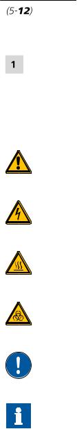
2.4Symbols and conventions
The following symbols and formatting may appear in this documentation:
|
|
|
Cross-reference to figure legend |
|
|
|
The first number refers to the figure number, the sec- |
|
|
|
ond to the instrument part in the figure. |
|
|
|
|
|
|
|
Instruction step |
|
|
|
Carry out these steps in the sequence shown. |
|
|
|
|
|
Method |
Dialog text, parameter in the software |
|
|
|
|
|
|
File New |
Menu or menu item |
|
|
|
|
|
|
[Next] |
Button or key |
|
|
|
|
|
|
|
|
WARNING |
|
|
|
This symbol draws attention to a possible life-threat- |
|
|
|
ening hazard or risk of injury. |
|
|
|
|
|
|
|
WARNING |
|
|
|
This symbol draws attention to a possible hazard due |
|
|
|
to electrical current. |
|
|
|
|
|
|
|
WARNING |
|
|
|
This symbol draws attention to a possible hazard due |
|
|
|
to heat or hot instrument parts. |
|
|
|
|
|
|
|
WARNING |
|
|
|
This symbol draws attention to a possible biological |
|
|
|
hazard. |
|
|
|
|
|
|
|
CAUTION |
|
|
|
This symbol draws attention to possible damage to |
|
|
|
instruments or instrument parts. |
|
|
|
|
|
|
|
NOTE |
|
|
|
|
|
|
|
This symbol highlights additional information and |
|
|
|
tips. |
|
|
|
|
940 Professional IC Vario ONE/SeS/HPG (2.940.1440) |
7 |

3.1 Front |
|
3 Overview of the instrument
3.1Front
Figure 1 Front
1 |
Bottle holder |
|
2 |
Detector chamber |
|
Offers space for the eluent bottle and addi- |
|
|
Offers space for two embedded detectors |
|
tional accessories. |
|
|
and additional accessories. |
|
|
|
|
|
3 |
Column holder |
4 |
Metrohm CO2 Suppressor (MCS) |
|
|
For a third separation column outside the |
|
|
|
column thermostat.
8 |
940 Professional IC Vario ONE/SeS/HPG (2.940.1440) |
Loading...