


885
Table of contents
 Loading...
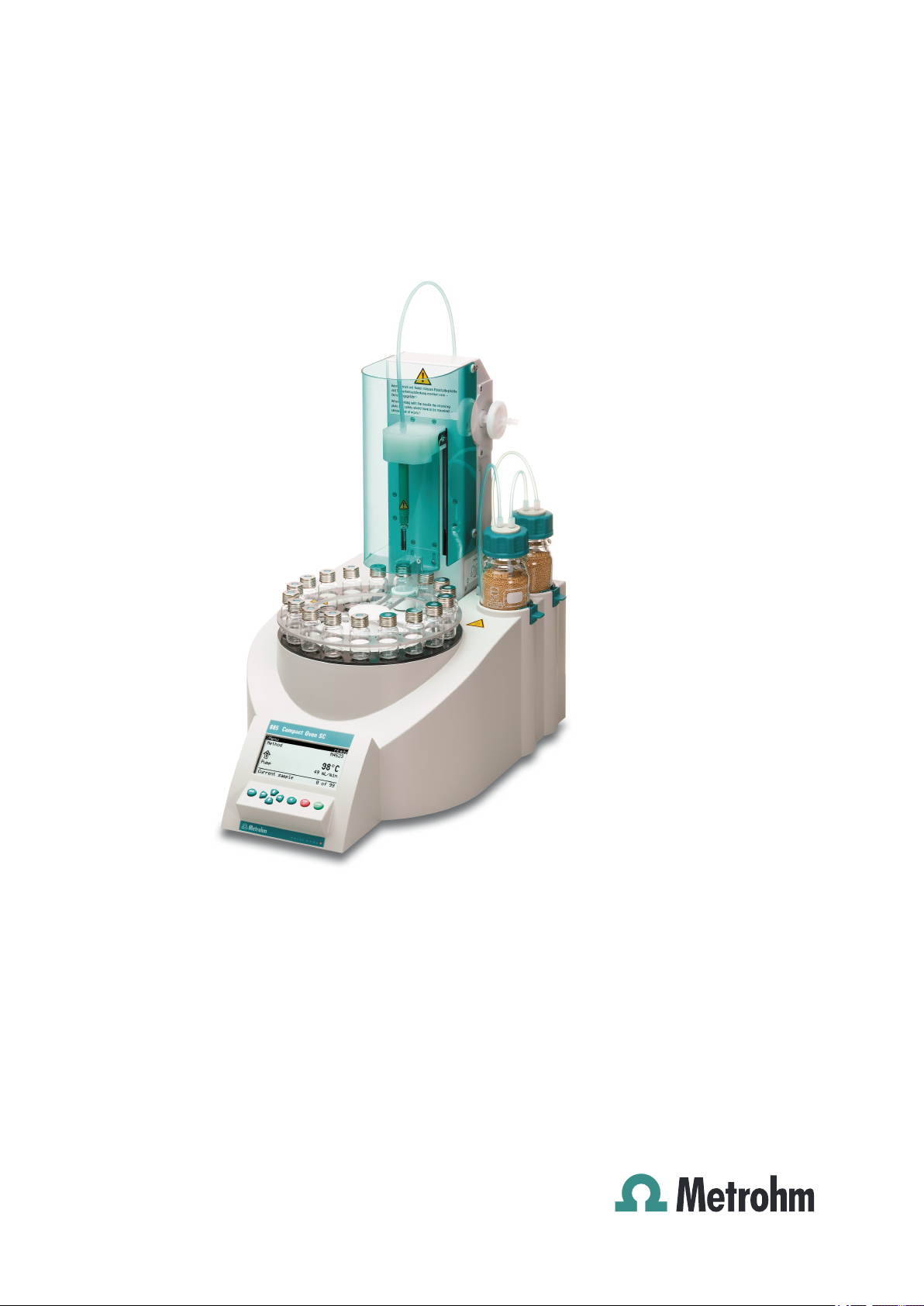
885 Compact Oven SC
Manual
8.885.8002EN


Metrohm AG
CH-9101 Herisau
Switzerland
Phone +41 71 353 85 85
Fax +41 71 353 89 01
info@metrohm.com
www.metrohm.com
885 Compact Oven SC
Manual
8.885.8002EN 05.2011 dm

Teachware
Metrohm AG
CH-9101 Herisau
teachware@metrohm.com
This documentation is protected by copyright. All rights reserved.
Although all the information given in this documentation has been
checked with great care, errors cannot be entirely excluded. Should you
notice any mistakes please send us your comments using the address
given above.
Documentation in additional languages can be found on
http://products.metrohm.com under Literature/Technical documenta-
tion.

■■■■■■■■■■■■■■■■■■■■■■
Table of contents
1 Introduction 1
1.1 Instrument description ......................................................... 1
1.1.1 Instrument components .......................................................... 1
1.1.2 Intended use ........................................................................... 2
1.2 About the documentation ................................................... 2
1.2.1 Symbols and conventions ........................................................ 2
1.3 Safety instructions ................................................................ 3
1.3.1 General notes on safety ........................................................... 3
1.3.2 Electrical safety ........................................................................ 3
1.3.3 Tubing and capillary connections ............................................. 4
1.3.4 Personnel safety ...................................................................... 5
1.3.5 Flammable solvents and chemicals ........................................... 6
1.3.6 Recycling and disposal ............................................................. 6
2 Overview of the instrument 7
Table of contents
3 Installation 9
3.1 Setting up the instrument .................................................... 9
3.1.1 Packaging ................................................................................ 9
3.1.2 Checks .................................................................................... 9
3.1.3 Location .................................................................................. 9
3.2 Mounting the stand plate .................................................... 9
3.3 Removing the safety shield ............................................... 10
3.4 Mounting the needles ........................................................ 11
3.5 Assembling the drying flasks ............................................ 13
3.6 Mounting the heating tubing ............................................ 15
3.7 Mounting the safety shield ................................................ 16
3.8 Mounting the dust filter .................................................... 17
3.9 Assembling the air/nitrogen connector ............................ 18
3.10 Inserting the heating tube into the KF titration cell ....... 19
3.11 Remote connections ........................................................... 21
3.11.1 Remote cable ........................................................................ 21
3.11.2 Example systems .................................................................... 21
885 Compact Oven SC
3.12 Connecting a keyboard, printer and other USB devi-
ces ........................................................................................ 23
3.13 Connecting the mains cable .............................................. 25
■■■■■■■■
III

Table of contents
■■■■■■■■■■■■■■■■■■■■■■
4 Automation sequence 26
4.1 Execution sequences .......................................................... 26
4.2 Oven heating ....................................................................... 27
5 Operation 28
5.1 Switching the instrument on and off ............................... 28
5.2 Fundamentals of operation ............................................... 28
5.2.1 The keypad ............................................................................ 28
5.2.2 Structure of the dialog windows ............................................ 29
5.2.3 Navigating in the dialog ......................................................... 29
5.2.4 Entering text and numbers ..................................................... 29
5.3 Methods .............................................................................. 30
5.3.1 Creating a new method ......................................................... 30
5.3.2 Saving a method ................................................................... 31
5.3.3 Loading a method ................................................................. 32
5.3.4 Exporting a method ............................................................... 33
5.4 Performing a sample series ............................................... 34
5.4.1 Starting the sample series ...................................................... 34
5.4.2 Pausing a sample series and continuing ................................. 35
5.5 Printing a report manually ................................................. 36
5.6 Manual control ................................................................... 37
5.6.1 Rotating the sample rack ....................................................... 37
5.6.2 Moving the lift ....................................................................... 38
5.6.3 Switching the oven on/off ..................................................... 39
5.6.4 Entering the oven temperature .............................................. 39
5.6.5 Switching the gas flow on/off ................................................ 39
5.6.6 Entering the flow rate ............................................................ 40
6 System settings 41
6.1 Basic settings ...................................................................... 41
6.2 File management ................................................................ 44
6.3 Oven settings (heater) ........................................................ 45
6.4 Lift settings (Lift) ................................................................ 46
6.5 Configuring external devices ............................................. 47
6.6 Instrument diagnosis .......................................................... 49
6.6.1 Loading program versions and language files ......................... 49
6.6.2 Diagnosis functions ............................................................... 50
7 Parameters 51
■■■■■■■■
IV
7.1 Automation ......................................................................... 51
7.2 Reports ................................................................................ 53
885 Compact Oven SC

■■■■■■■■■■■■■■■■■■■■■■
8 Carrying out a determination 54
9 Handling and maintenance 58
10 Appendix 60
Table of contents
8.1 Conditioning the system .................................................... 54
8.1.1 Preparing the KF titration cell ................................................. 54
8.1.2 Preparing the 885 Compact Oven SC ..................................... 55
9.1 General ................................................................................ 58
9.2 Quality Management and validation with Metrohm ....... 58
10.1 Practical notes .................................................................... 60
10.2 Remote interface ................................................................ 61
10.2.1 Pin assignment of the remote interface .................................. 61
10.2.2 Status diagram of the remote interface .................................. 62
10.3 System initialization ........................................................... 62
10.4 Literature ............................................................................. 64
11 Troubleshooting 65
11.1 885 Compact Oven SC ........................................................ 65
12 Technical specifications 66
12.1 Lift ........................................................................................ 66
12.2 Turntable ............................................................................. 66
12.3 Oven ..................................................................................... 66
12.4 Gas flow .............................................................................. 67
12.5 Outlet heater ....................................................................... 67
12.6 Interfaces and connectors ................................................. 67
12.7 Mains connection ............................................................... 67
12.8 Reference conditions .......................................................... 67
12.9 Safety specifications ........................................................... 68
12.10 Electromagnetic compatibility (EMC) ................................ 68
12.11 Ambient temperature ......................................................... 68
12.12 Dimensions .......................................................................... 69
13 Conformity and warranty 70
885 Compact Oven SC
13.1 Declaration of Conformity ................................................. 70
13.2 Warranty (guarantee) ......................................................... 71
13.3 Quality Management Principles ........................................ 72
■■■■■■■■
V

Table of contents
■■■■■■■■■■■■■■■■■■■■■■
14 Accessories 74
14.1 Scope of delivery 2.885.0010 ............................................ 74
14.2 Optional accessories ........................................................... 80
Index 82
■■■■■■■■
VI
885 Compact Oven SC

■■■■■■■■■■■■■■■■■■■■■■
Table of figures
Figure 1 Mounting the stand plate ................................................................ 10
Figure 2 Removing the coverings .................................................................. 10
Figure 3 Mounting the needles ..................................................................... 12
Figure 4 Connecting the tubing to the gas outlet .......................................... 13
Figure 5 Preparing the drying flasks ............................................................... 13
Figure 6 Mounting drying flasks and tubings ................................................. 14
Figure 7 Mounting the heating tubing .......................................................... 15
Figure 8 Connecting the heating tubing ........................................................ 16
Figure 9 Mounting the coverings .................................................................. 17
Figure 10 Mounting the dust filter .................................................................. 18
Figure 11 External gas supply connection ........................................................ 18
Figure 12 Coulometric KF titration cell ............................................................ 19
Figure 13 Volumetric KF titration cell .............................................................. 20
Figure 14 Remote connection 885 Compact Oven SC - Coulometer or 7xx KF
Titrino ............................................................................................. 22
Figure 15 Remote connection 885 Compact Oven SC - Remote Box - 851/852
Titrando .......................................................................................... 22
Figure 16 Connecting USB devices .................................................................. 23
Figure 17 Connecting the USB stick ................................................................ 24
Figure 18 Connecting the 6.2147.000 USB keyboard with USB stick and
printer ............................................................................................. 25
Figure 19 Connecting the mains cable ............................................................ 25
Figure 20 Keypad 885 Compact Oven SC ........................................................ 28
Figure 21 Directory structure on the USB stick ................................................. 44
Figure 22 Pin assignment of remote socket and plug ...................................... 61
Figure 23 Remote status diagram .................................................................... 62
Table of figures
885 Compact Oven SC
■■■■■■■■
VII


■■■■■■■■■■■■■■■■■■■■■■
1 Introduction
1.1 Instrument description
The 885 Compact Oven SC is used whenever the heating up of a sample
and/or the thermal expulsion of moisture in solids or liquids is required. In
combination with a coulometric or volumetric KF titrator, the 885 Compact Oven SC is the ideal analysis system for water determination in samples that contain disruptive components or from which moisture can be
removed only with difficulty.
One of its decisive advantages is the reduction of sample preparation to a
minimum. Thanks to the use of hermetically sealed sample vessels ("headspace vials"), the filling of the samples can be accomplished directly onsite. The PTFE-coated septa guarantee a constant, non-falsified water content, even after prolonged holding times.
1 Introduction
Thanks to the combination of a sample changer with an oven module,
automated processing of several samples in a single sample series is possible. This ensures that only the smallest possible amount of work is
required.
The sample heated in the oven module releases its moisture in the form of
water vapor, which is conveyed into a measuring cell with the aid of a gas
flow. An air pump is installed for the purpose of generating the gas flow.
An inlet valve is available for nitrogen or other inert gases. The determination of the moisture can be accomplished in the measuring cell either coulometrically or volumetrically according to Karl Fischer.
1.1.1 Instrument components
The 885 Compact Oven SC has the following components:
■ Turntable
Permanently mounted sample rack with 17 positions for sample vials
and 1 position for a conditioning vessel.
■ Lift with working head
Working head with needle adapter and tubing for the gas flow.
■ Oven
Oven module made of aluminum with software-operated temperature
control for heating the sample vessel.
■ Fan
Propeller fan for cooling the oven module.
■ Inlet valve
Valve for switching over the source of the gas flow.
885 Compact Oven SC
■■■■■■■■
1
1.2 About the documentation
■ Air pump
■ Outlet heater
■ Operating unit
1.1.2 Intended use
The 885 Compact Oven SC is designed for usage as an auxiliary device for
automated sample preparation in analytical laboratories. Its main area of
application is moisture determination according to Karl Fischer (coulometric or volumetric). The 885 Compact Oven SC enables the application of
thermal gas extraction technology.
This instrument is suitable for processing chemicals and flammable samples. The usage of the 885 Compact Oven SC therefore requires that the
user has basic knowledge and experience in the handling of toxic and
caustic substances. Knowledge with respect to the application of the fire
prevention measures prescribed for laboratories is also mandatory.
■■■■■■■■■■■■■■■■■■■■■■
Pump for generating the gas flow.
Heating tubing for preventing the condensation of moisture.
Monochrome LCD display and keyboard.
1.2 About the documentation
Caution
Please read through this documentation carefully before putting the
instrument into operation. The documentation contains information
and warnings which the user must follow in order to ensure safe operation of the instrument.
1.2.1 Symbols and conventions
The following symbols and styles are used in this documentation:
Cross-reference to figure legend
The first number refers to the figure number, the
second to the instrument part in the figure.
Instruction step
Carry out these steps in the sequence shown.
Method Dialog text, parameter in the software
■■■■■■■■
2
File ▶ New
Menu or menu item
[Next] Button or key
885 Compact Oven SC
■■■■■■■■■■■■■■■■■■■■■■
1 Introduction
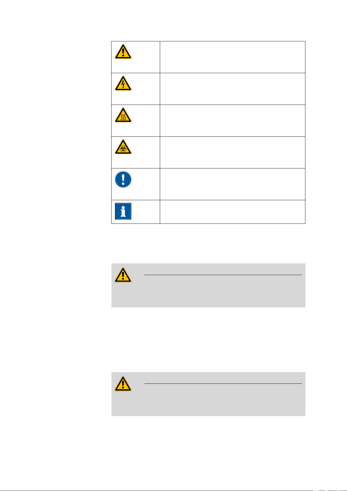
Warning
This symbol draws attention to a possible life hazard
or risk of injury.
Warning
This symbol draws attention to a possible hazard due
to electrical current.
Warning
This symbol draws attention to a possible hazard due
to heat or hot instrument parts.
Warning
This symbol draws attention to a possible biological
hazard.
Caution
This symbol draws attention to a possible damage of
instruments or instrument parts.
1.3 Safety instructions
1.3.1 General notes on safety
Warning
This instrument may only be operated in accordance with the specifications in this documentation.
This instrument has left the factory in a flawless state in terms of technical
safety. To maintain this state and ensure non-hazardous operation of the
instrument, the following instructions must be observed carefully.
1.3.2 Electrical safety
The electrical safety when working with the instrument is ensured as part
of the international standard IEC 61010.
Note
This symbol marks additional information and tips.
885 Compact Oven SC
Warning
Only personnel qualified by Metrohm are authorized to carry out service
work on electronic components.
■■■■■■■■
3
1.3 Safety instructions
■■■■■■■■■■■■■■■■■■■■■■
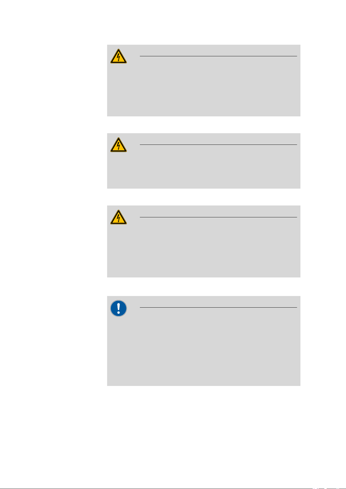
Warning
Never open the housing of the instrument. The instrument could be
damaged by this. There is also a risk of serious injury if live components
are touched.
There are no parts inside the housing which can be serviced or replaced
by the user.
Mains voltage
Warning
An incorrect mains voltage can damage the instrument.
Only operate this instrument with a mains voltage specified for it (see
rear panel of the instrument).
Protection against electrostatic charges
Warning
Electronic components are sensitive to electrostatic charges and can be
destroyed by discharges.
Always pull the mains cable out of the mains connection socket before
connecting or disconnecting electrical appliances on the rear panel of
the instrument.
1.3.3 Tubing and capillary connections
Caution
Leaks in tubing and capillary connections are a safety risk. Tighten all
connections well by hand. Avoid applying excessive force to tubing
connections. Damaged tubing ends lead to leakage. Appropriate tools
can be used to loosen connections.
Check the connections regularly for leakage. If the instrument is used
mainly in unattended operation, then weekly inspections are mandatory.
■■■■■■■■
4
885 Compact Oven SC

■■■■■■■■■■■■■■■■■■■■■■
1.3.4 Personnel safety
Wear protective goggles and working clothes suitable for laboratory
work while operating the 885 Compact Oven SC. It is also advisable to
wear gloves when caustic liquids are used or in situations where glass
vessels could break.
The oven module can exhibit temperatures of up to 250 °C. Sample
vessels and components of the sample rack can also become so hot
(<60 °C), that the skin could suffer burns in the event of contact.
Never touch the rack, sample vessels or oven when the heating is
turned on. Be aware of the current value on the temperature display.
1 Introduction
Warning
Warning
Wear working gloves.
Do not fail to switch off the device before attempting to clean it and
wait until the oven has cooled down.
Warning
Always install the safety shield supplied with the equipment before
using the instrument for the first time. Pre-installed safety shields are
not allowed to be removed.
The 885 Compact Oven SC may not be operated without a safety
shield!
Warning
Personnel are not permitted to reach into the working area of the
instrument while operations are running!
A considerable risk of injury exists for the user.
885 Compact Oven SC
■■■■■■■■
5
1.3 Safety instructions
Warning
In the event of a possible jamming of a drive, the mains plug must be
pulled out of the socket immediately. Do not attempt to free jammed
sample vessels or other parts while the instrument is switched on. A
jamming can only be cleared when the instrument is in a voltage-free
status; this action generally involves a considerable risk of injury.
Warning
The 885 Compact Oven SC is not suitable for usage in biochemical,
biological or medical environments in its basic equipment version.
Appropriate protective measures must be implemented in the event
that potentially infectious samples or reagents are being processed.
1.3.5 Flammable solvents and chemicals
■■■■■■■■■■■■■■■■■■■■■■
Warning
All relevant safety measures are to be observed when working with
flammable solvents and chemicals.
■ Set up the instrument in a well-ventilated location.
■ Keep all sources of flame far from the workplace.
■ Clean up spilled liquids and solids immediately.
■ Follow the safety instructions of the chemical manufacturer.
1.3.6 Recycling and disposal
This product is covered by European Directive 2002/96/EC, WEEE – Waste
from Electrical and Electronic Equipment.
The correct disposal of your old equipment will help to prevent negative
effects on the environment and public health.
More details about the disposal of your old equipment can be obtained
from your local authorities, from waste disposal companies or from your
local dealer.
■■■■■■■■
6
885 Compact Oven SC
■■■■■■■■■■■■■■■■■■■■■■
1
2
3
4
5
6
7
8
9
10
11
12
13
14
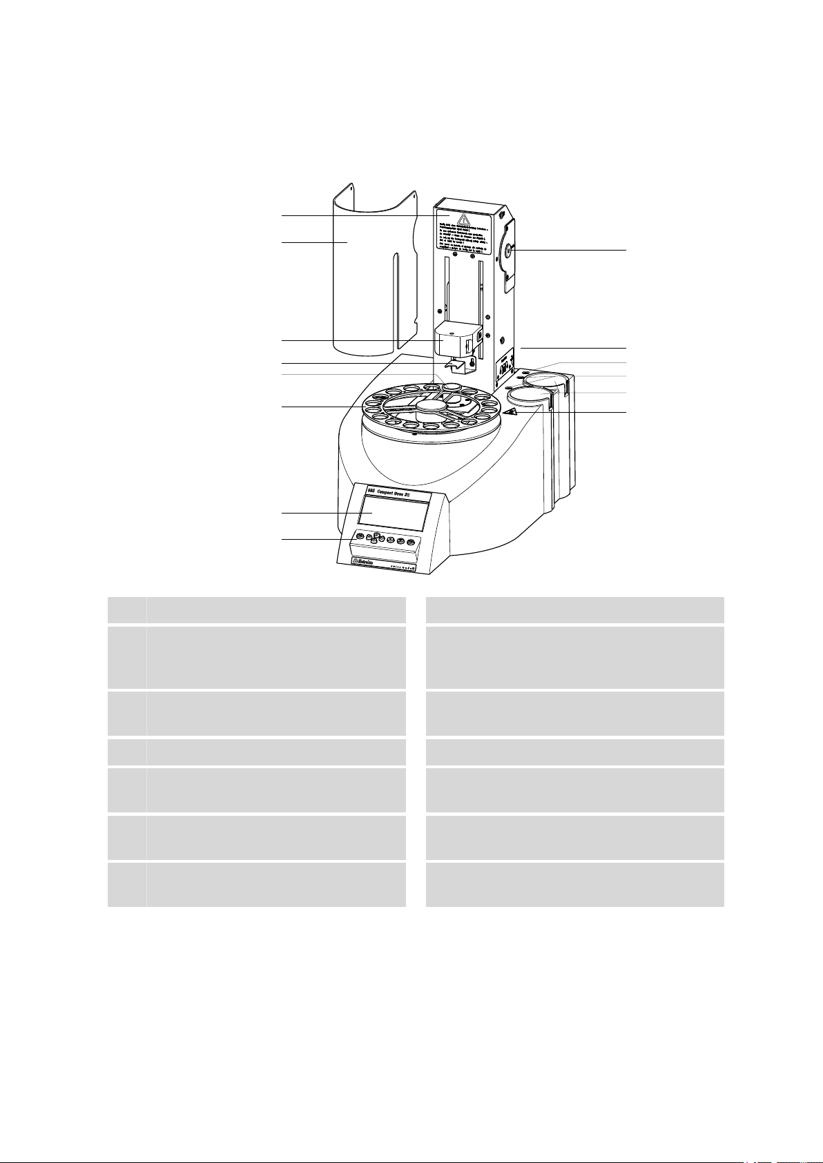
2 Overview of the instrument
2 Overview of the instrument
Warning instruction
1
Lift with distributor
3
Conditioning position
5
For a conditioning vial.
Display
7
Air pump inlet
9
With 6.2724.010 dust filter.
Gas outlet
11
For the tubing for testing. With M6 thread.
Recesses in the housing
13
For the drying flasks.
Safety shield (6.2751.170)
2
Deflector sheet
4
For deflecting the vial while the lift is traveling upwards.
Sample rack
6
For 17 samples.
Keypad
8
Instruction sign
10
Displays the tubing of the drying flasks.
Gas connections
12
For the drying flasks. With M6 thread.
Warning symbol
14
Warns against hot surfaces.
885 Compact Oven SC
■■■■■■■■
7
■■■■■■■■■■■■■■■■■■■■■■
1
2
3
4
5
6
7
8
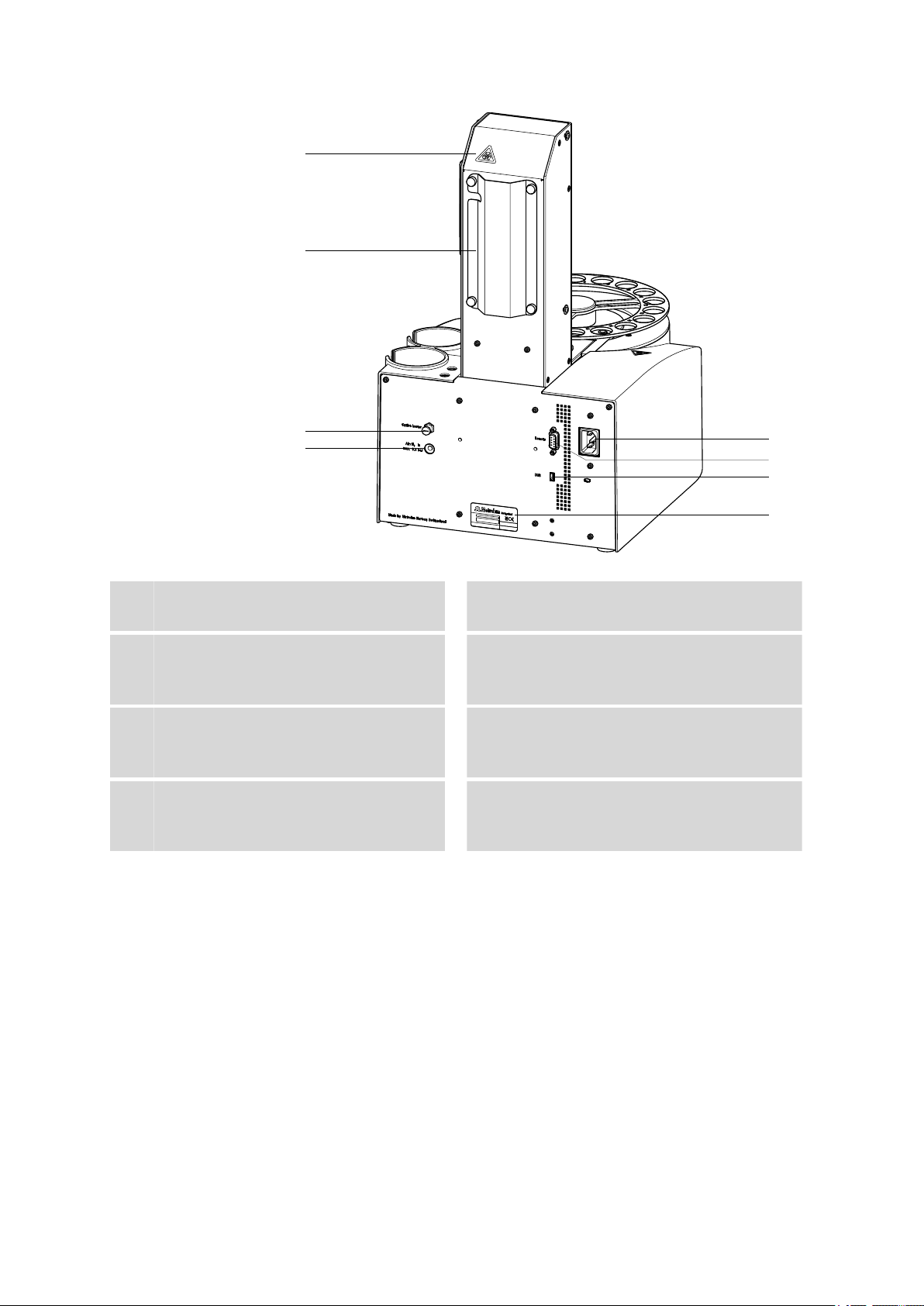
Warning symbol
1
See page 5
Outlet heater connection
3
For the heating tubing.
Mains connection socket
5
USB (OTG) connector
7
For connecting printers, USB sticks, USB
hubs, etc.
Tubing and cable cover
2
Air/nitrogen connector
4
With M6 inner thread. Inlet for external gassing.
Remote connector
6
For connecting instruments with a remote
interface. D-Sub, 9-pin.
Type plate
8
Contains specifications concerning mains
voltage and serial number.
■■■■■■■■
8
885 Compact Oven SC

■■■■■■■■■■■■■■■■■■■■■■
3 Installation
3.1 Setting up the instrument
3.1.1 Packaging
The instrument is supplied in highly protective special packaging together
with the separately packed accessories. Keep this packaging, as only this
ensures safe transportation of the instrument.
3.1.2 Checks
Immediately after receipt, check whether the shipment has arrived complete and without damage by comparing it with the delivery note.
3.1.3 Location
The instrument has been developed for operation indoors and may not be
used in explosive environments.
3 Installation
Place the instrument in a location of the laboratory which is suitable for
operation, free of vibrations, protected from corrosive atmosphere, and
contamination by chemicals.
The instrument should be protected against excessive temperature fluctuations and direct sunlight.
3.2 Mounting the stand plate
The titration cell must be fitted as close to the device as possible. Two
stand plates (6.2001.050 and 6.2001.060) with support rods are available
for this purpose, each of which is supplied with a KF titrator.
885 Compact Oven SC
■■■■■■■■
9

3.3 Removing the safety shield
1
2
3
6.2001.060 6.2001.050
6.2016.030
1
1
2
■■■■■■■■■■■■■■■■■■■■■■
Figure 1 Mounting the stand plate
Proceed as follows:
Screw the stand plate to the base of the 885 Compact Oven SC with
1
the screws provided, see figure.
Guide the large cylinder screw into the opening of the stand plate
2
from the bottom.
Screw the 6.2016.030 support rod tight on the cylinder screw. Fas-
3
ten in place with a hexagon key.
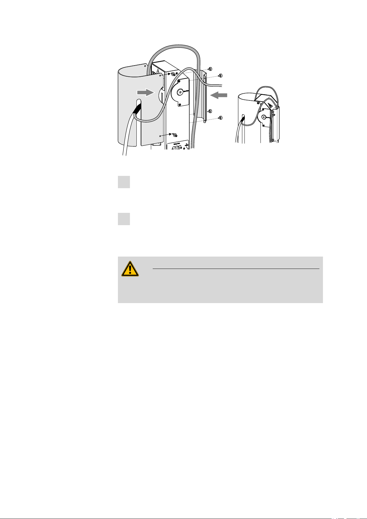
3.3 Removing the safety shield
Figure 2 Removing the coverings
■■■■■■■■
10
885 Compact Oven SC

■■■■■■■■■■■■■■■■■■■■■■
If you remove the safety shield before, the installation of the accessories is
easier to carry out. Proceed as follows:
Loosen the hexagon screws on the sides of the tower and remove
1
the safety shield.
Loosen the knurled screws on the rear of the tower and remove the
2
cable cover.
Do not forget to refasten the safety shields after the installation of the
accessories.
3.4 Mounting the needles
The length of the needle holder defines how deeply the piercing needle
penetrates the sample vessel.
If there is a danger that the heated sample could clog the needle, then
use the 6.2049.050 needle holder which is 73 mm in length. In this
case the piercing needle penetrates the sample vessel only slightly deeper
than the exhaust air needle and has no contact with the sample itself.
3 Installation
Caution
Movement with the needle holder 6.2049.050 may not extend more
deeply than up to Lift position 78 mm.
The 6.2049.040 needle holder, which is 58 mm in length, ensures that
the needle penetrates the liquid or powdery sample. The carrier gas can
flow through the sample and effect an efficient expulsion of the moisture
it contains. The 6.2049.040 needle holder can be ordered from Metrohm
if required.
885 Compact Oven SC
■■■■■■■■
11
3.4 Mounting the needles
1
4
2
3
6.1805.060
6.2049.050
6.2816.080
6.2816.070
■■■■■■■■■■■■■■■■■■■■■■
Figure 3 Mounting the needles
Mount the needles as follows:
Screw the 6.2049.050 needle holder into the distributor on the
1
guide head.
Screw the 6.2816.080 exhaust air needle onto the Luer connec-
2
tor of the needle holder.
Carefully guide the 6.2816.070 piercing needle into the opening
3
of the distributor from above and allow it to drop down.
■■■■■■■■
12
Note
Take care to ensure that the white PTFE seal is positioned securely
on the needle.
Screw the 6.1805.060 FEP tubing by hand onto the opening of
4
the distributor.
Tightly screw the other end of the tubing to the gas outlet opening
5
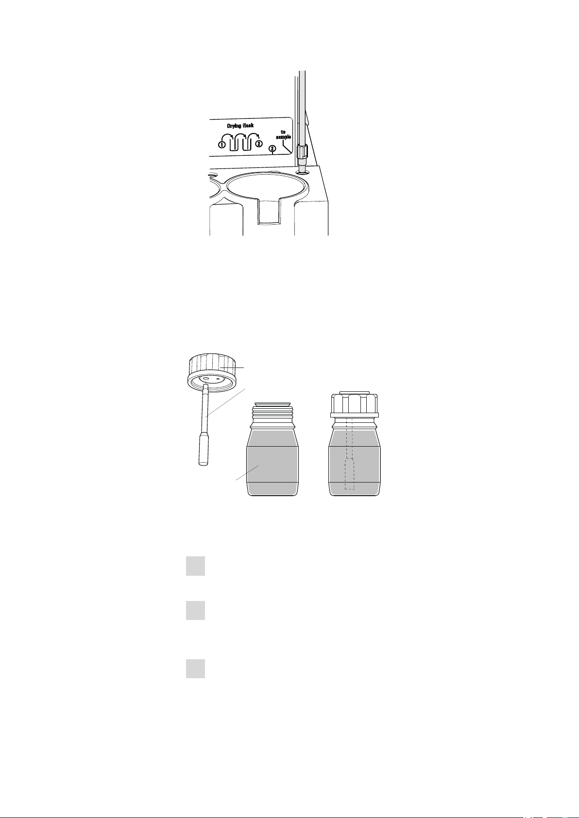
(labeled with to sample) next to the tower, see figure.
885 Compact Oven SC
■■■■■■■■■■■■■■■■■■■■■■
1
2
3
6.1608.050
6.1821.040
6.1602.145
6.2811.000
Figure 4 Connecting the tubing to the gas outlet
3.5 Assembling the drying flasks
Two drying flasks with desiccant are integrated into the gas flow in order
to dry the gas that is conveyed. Dust (e.g. from the desiccant) must be
prevented from finding its way into the sample vessel.
3 Installation
885 Compact Oven SC
Figure 5 Preparing the drying flasks
Prepare both drying flasks as follows:
Fill both 6.1608.050 drying flasks with 6.2811.000 molecular
1
sieve.
Screw one 6.1821.040 filter tube into each of the 6.1602.145
2
drying flask covers from below. Tighten the filter tubes well by
hand.
Screw the two drying flask covers with the filter tubes onto the dry-
3
ing flasks. Tighten the covers well by hand.
■■■■■■■■
13
3.5 Assembling the drying flasks
1
2
2
3
3
4
1
6.1805.080
6.1805.080
6.1805.010
■■■■■■■■■■■■■■■■■■■■■■
Note
If drying flask covers or filter tubes are not sufficiently tightly
screwed on, then this will prevent a precise, regular gas flow. The
error message "Flow rate error" will appear as a rule when there
are leaks in the threaded connections.
■■■■■■■■
14
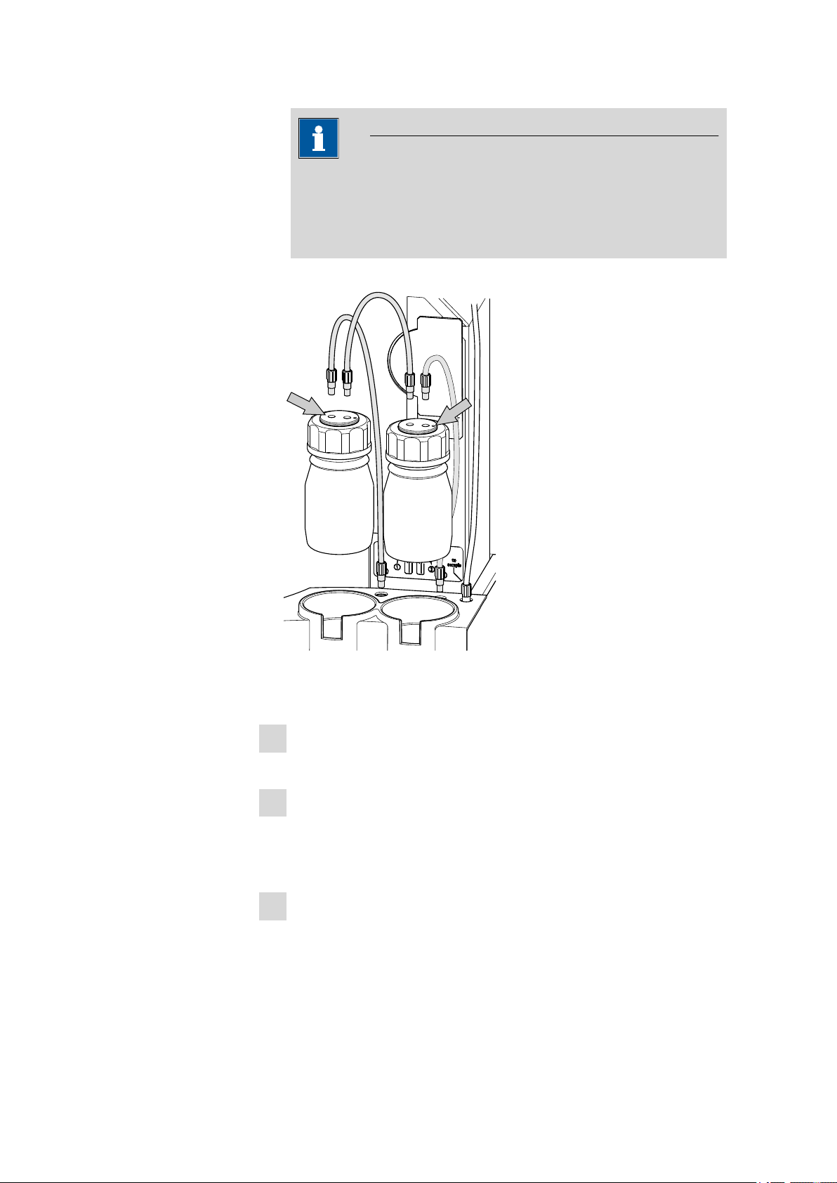
Figure 6 Mounting drying flasks and tubings
Mount the FEP tubings as follows:
Insert the two drying flasks that have been prepared into the holders,
1
see figure.
Screw one 6.1805.080 FEP tubing (25 cm in length) to the gas outlet
2
(at the rear on the left, labeled 1). Screw the other tubing end on the
front drying flask to the M6 connector without point marking (see
left-hand arrow).
Screw the second 6.1805.080 FEP tubing (25 cm in length) to the
3
gas inlet (at the rear on the right, labeled 2). Screw the other tubing
end on the rear drying flask to the M6 connector with point marking
(see right-hand arrow).
885 Compact Oven SC
■■■■■■■■■■■■■■■■■■■■■■
6.2043.005
6.1830.030
3 Installation
Screw the 6.1805.010 FEP tubing (13 cm in length) tightly onto the
4
remaining M6 connectors of the drying flasks.
The figure Drying flask on the right-hand side of the instrument displays the diagram for the tubing.
Note
Tighten the screw connections well by hand.
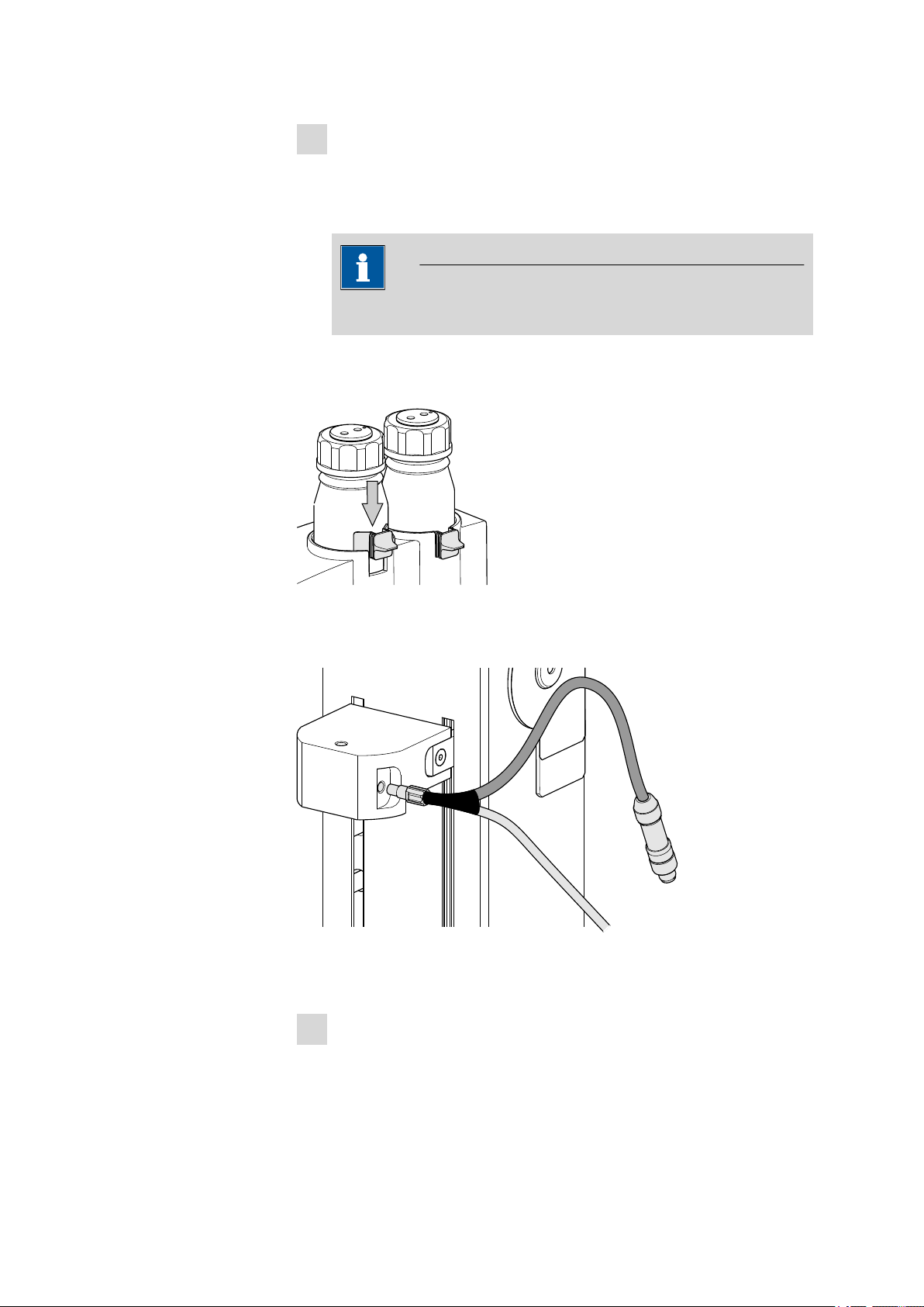
You can fasten the drying flasks with the 6.2043.005 holding clamps, see
figure.
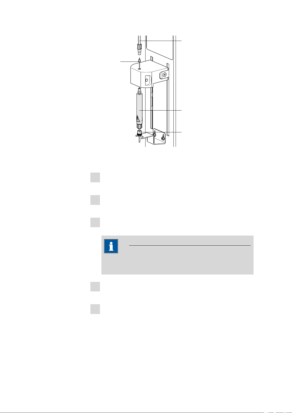
3.6 Mounting the heating tubing
Figure 7 Mounting the heating tubing
Proceed as follows:
Screw the M6 connector of the 6.1830.030 heating tubing into
1
the side opening of the distributor on the guide head.
885 Compact Oven SC
■■■■■■■■
15
3.7 Mounting the safety shield
■■■■■■■■■■■■■■■■■■■■■■
Connect the heating tubing cable to the Outlet heater connector
2
on the rear of the instrument.
Figure 8 Connecting the heating tubing
Rotate the plug in such a way that the three contact pins match the
alignment of the corresponding openings on the socket. Press the
plug against the socket and rotate the front knurled screw in a clockwise direction.
Note
The heating jacket of the heating tubing is heated up to approx.
40…50 °C as soon as the instrument is switched on. This prevents
the condensation of moisture in the tubing when this is expelled
from the sample and transferred with the aid of a carrier gas into a
KF titration cell.
3.7 Mounting the safety shield
Now you can remount the safety shield. Proceed as follows:
■■■■■■■■
16
885 Compact Oven SC
■■■■■■■■■■■■■■■■■■■■■■
1
1
2
2
Figure 9 Mounting the coverings
Fasten the safety shield with the four hexagon screws to the sides of
1
the tower. The heating tubing and its connection cable must be guided through the slot of the cover.
Fasten the cable cover with the four knurled screws to the rear side
2
of the tower. The gas supply tubing must be guided underneath the
cover. The connection cable of the heating tubing must be guided
through the lateral recess of the cover, see figure.
3 Installation
Warning
The 885 Compact Oven SC may not be operated without a safety
shield!
3.8 Mounting the dust filter
The built-in air pump must be protected against dust. A 6.2724.010
dust filter must be placed on the air inlet (Inlet filter) on the right-hand
side of the housing for this reason.
885 Compact Oven SC
■■■■■■■■
17
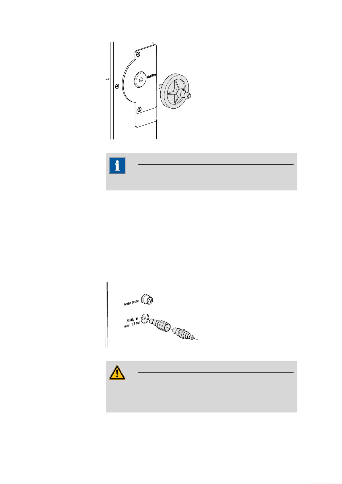
3.9 Assembling the air/nitrogen connector
6.2724.010
6.1808.050
6.1808.040
Figure 10 Mounting the dust filter
The dust filter should be replaced once a year.
■■■■■■■■■■■■■■■■■■■■■■
Note
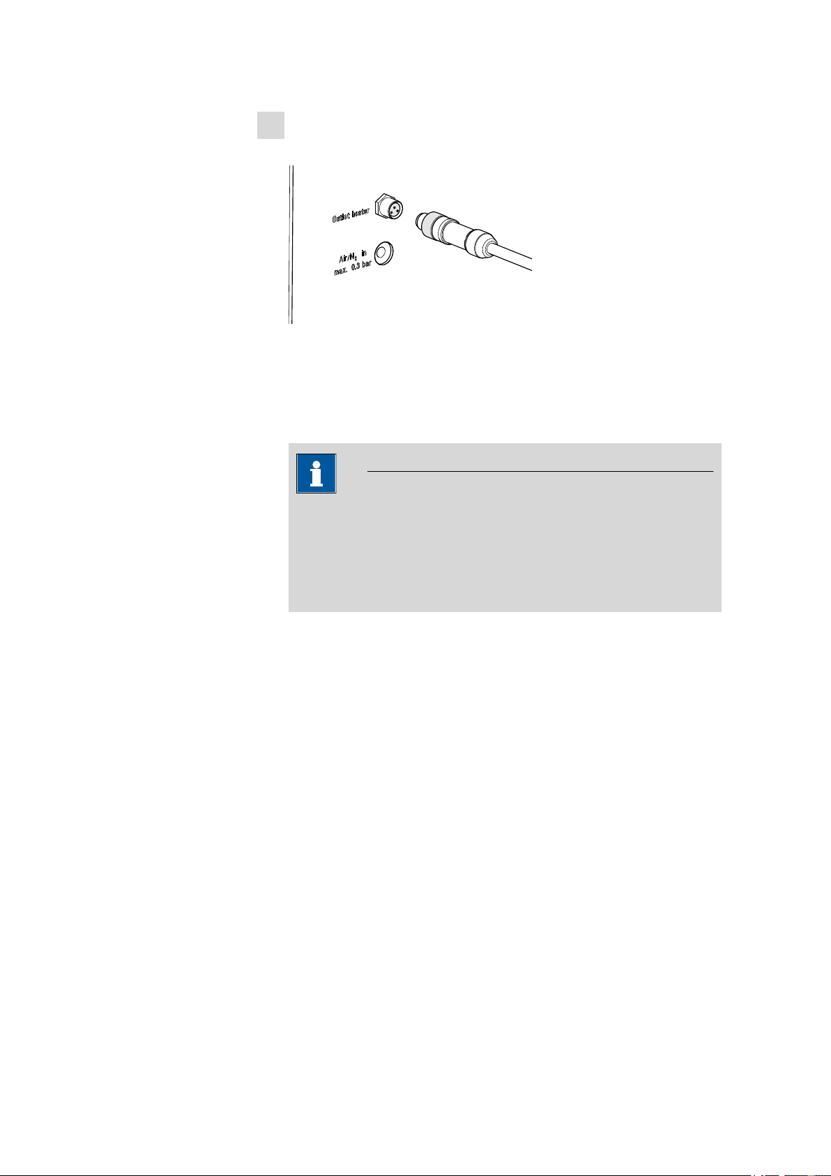
3.9 Assembling the air/nitrogen connector
If compressed air, nitrogen or another gas is to be used for transferring
the expelled moisture, then a separate connector is available on the rear
of the instrument.
A tubing with M6 thread can be connected directly to the connector Air/
N2 in. Enclosed with the instrument is the 6.1808.040 M6/M8 tubing
adapter for a tubing with an M8 thread. The 6.1808.050 M8/tubing
olive can also be put in place in order to connect a simple tubing.
Figure 11 External gas supply connection
Warning
■■■■■■■■
18
If gas is supplied from a pressure line or a pressure vessel, then it is
imperative that a pressure reduction valve be placed upstream. The gas
pressure may not exceed a maximum overpressure level of 0.3 bar.
885 Compact Oven SC
Loading...