


 Loading...
940 Professional IC Vario
940 Professional IC Vario ONE/SeS/PP/Prep 1
Manual
8.940.8019EN

Metrohm AG CH-9100 Herisau Switzerland
Phone +41 71 353 85 85 Fax +41 71 353 89 01 info@metrohm.com www.metrohm.com
940 Professional IC Vario
940 Professional IC Vario ONE/SeS/
PP/Prep 1
2.940.1510
Manual
8.940.8019EN |
11.2013 zst |
Teachware Metrohm AG CH-9100 Herisau
teachware@metrohm.com
This documentation is protected by copyright. All rights reserved.
Although all the information given in this documentation has been checked with great care, errors cannot be entirely excluded. Should you notice any mistakes please send us your comments using the address given above.
Documentation in additional languages can be found on
http://documents.metrohm.com.
|
Table of contents |
Table of contents
1 Introduction |
1 |
|
1.1 |
Instrument description ......................................................... |
1 |
1.2 |
Intended use ......................................................................... |
3 |
1.3 |
Safety instructions ................................................................ |
4 |
1.3.1 |
General notes on safety ........................................................... |
4 |
1.3.2 |
Electrical safety ........................................................................ |
4 |
1.3.3 |
Tubing and capillary connections ............................................. |
5 |
1.3.4 |
Flammable solvents and chemicals ........................................... |
5 |
1.3.5 |
Recycling and disposal ............................................................. |
5 |
1.4 |
Symbols and conventions .................................................... |
6 |
2 Overview of the instrument |
7 |
|
2.1 |
Front ...................................................................................... |
7 |
2.2 |
Rear ........................................................................................ |
9 |
2.3 |
Feed-throughs for capillaries and cables .......................... |
10 |
3 Installation |
|
14 |
3.1 |
Setting up the instrument .................................................. |
14 |
3.1.1 |
Packaging .............................................................................. |
14 |
3.1.2 |
Checks .................................................................................. |
14 |
3.1.3 |
Location ................................................................................ |
14 |
3.2 |
Capillary connections in the IC system ............................. |
14 |
3.3 |
Removing the handle ......................................................... |
17 |
3.4 |
Removing transport locking screws ................................. |
18 |
3.5 |
Connecting the drainage tubing and leak sensor ............ |
19 |
3.5.1 |
Installing the drainage tubing ................................................ |
19 |
3.5.2 |
Connecting the leak sensor .................................................... |
21 |
3.6 |
Column thermostat ............................................................ |
21 |
3.7 |
Connecting the eluent bottle ............................................. |
22 |
3.8 |
Connecting the eluent degasser ........................................ |
25 |
3.9 |
Installing the high-pressure pump .................................... |
25 |
3.10 |
Installing an inline filter ..................................................... |
26 |
3.11 |
Installing the pulsation absorber ...................................... |
27 |
3.12 |
Injection valve ..................................................................... |
28 |
3.13 |
Suppressor .......................................................................... |
30 |
3.13.1 |
Inserting the rotors ................................................................ |
30 |
940 Professional IC Vario ONE/SeS/PP/Prep 1 (2.940.1510) |
III |
Table of contents |
|
|
|
|
3.13.2 |
Connecting the suppressor .................................................... |
33 |
|
3.14 |
Peristaltic pump .................................................................. |
37 |
|
3.14.1 Installing the peristaltic pump ................................................ |
37 |
|
|
3.14.2 Mode of operation for the peristaltic pump ........................... |
43 |
|
|
3.15 |
Metrohm CO2 Suppressor (MCS) ....................................... |
44 |
|
3.15.1 General information on MCS ................................................. |
44 |
|
|
3.15.2 |
Connecting the MCS ............................................................. |
45 |
|
3.15.3 |
Installing adsorption cartridges .............................................. |
46 |
|
3.16 |
Installing the detector ........................................................ |
48 |
|
3.17 |
Connecting the sample degasser (optional) ..................... |
48 |
|
3.18 |
Connecting the instrument to a computer ....................... |
50 |
|
3.19 |
Connecting the instrument to the power supply ............. |
51 |
|
3.20 |
Initial start-up ..................................................................... |
52 |
|
3.21 |
Connecting and rinsing the guard column ....................... |
54 |
|
3.22 |
Connecting the separation column ................................... |
56 |
|
3.23 |
Conditioning ........................................................................ |
60 |
4 |
Operation |
|
62 |
5 |
Operation and maintenance |
63 |
|
|
5.1 |
IC system ............................................................................. |
63 |
|
5.1.1 |
Operation .............................................................................. |
63 |
|
5.1.2 |
Care ...................................................................................... |
63 |
|
5.1.3 Maintenance by Metrohm Service .......................................... |
63 |
|
|
5.1.4 Shutting down and starting back up ...................................... |
64 |
|
|
5.2 |
Capillary connections ......................................................... |
65 |
|
5.3 |
Servicing the door .............................................................. |
65 |
|
5.4 |
Column thermostat – Replacing the capillaries ............... |
65 |
|
5.5 |
Handling the eluent ............................................................ |
67 |
|
5.5.1 |
Manufacturing eluent ............................................................ |
67 |
|
5.5.2 |
Changing the eluent .............................................................. |
68 |
|
5.6 |
Servicing the eluent degasser ........................................... |
68 |
|
5.7 |
Notes on operating the high-pressure pump ................... |
69 |
|
5.8 |
Servicing the high-pressure pump .................................... |
70 |
|
5.9 |
Servicing the inline filter .................................................... |
83 |
|
5.10 |
Servicing the pulsation absorber ...................................... |
86 |
|
5.11 |
Injection valve ..................................................................... |
86 |
|
5.12 |
Suppressor .......................................................................... |
86 |
|
5.12.1 Notes for operating the suppressor ........................................ |
86 |
|
|
5.12.2 Taking care of the suppressor housing ................................... |
87 |
|
IV |
940 Professional IC Vario ONE/SeS/PP/Prep 1 (2.940.1510) |
|
|
Table of contents |
|
|
5.12.3 |
Servicing the suppressor ........................................................ |
87 |
|
5.13 |
Peristaltic pump .................................................................. |
94 |
|
5.13.1 Notes on operating the peristaltic pump ................................ |
94 |
|
|
5.13.2 Servicing the peristaltic pump ................................................ |
94 |
|
|
5.14 |
Servicing the Metrohm CO2 Suppressor (MCS) ................ |
96 |
|
5.14.1 Replacing the CO2 adsorption cartridge ................................. |
96 |
|
|
5.14.2 Regenerating the H2O adsorption cartridge ............................ |
96 |
|
|
5.15 |
Servicing the detector ........................................................ |
97 |
|
5.16 |
Rinsing the sample path .................................................... |
97 |
|
5.17 |
Separation column ............................................................. |
98 |
|
5.17.1 |
Separating efficiency .............................................................. |
98 |
|
5.17.2 Protecting the separation column .......................................... |
99 |
|
|
5.17.3 Storing the separation column ............................................... |
99 |
|
|
5.17.4 Regenerating the separation column ...................................... |
99 |
|
|
5.18 |
Quality Management and qualification with Metrohm 100 |
|
6 |
Troubleshooting |
101 |
|
|
6.1 |
........................................................................................... |
101 |
7 |
Technical specifications |
105 |
|
|
7.1 |
Reference conditions ........................................................ |
105 |
|
7.2 |
Device ................................................................................ |
105 |
|
7.3 |
Ambient conditions .......................................................... |
105 |
|
7.4 |
Housing ............................................................................. |
106 |
|
7.5 |
Leak sensor ....................................................................... |
106 |
|
7.6 |
Column thermostat .......................................................... |
106 |
|
7.7 |
Eluent degasser ................................................................ |
107 |
|
7.8 |
High-pressure pump ......................................................... |
107 |
|
7.9 |
Injection valve ................................................................... |
108 |
|
7.10 |
Suppressor ........................................................................ |
108 |
|
7.11 |
Peristaltic pump ................................................................ |
108 |
|
7.12 |
Metrohm CO2 Suppressor (MCS) ..................................... |
109 |
|
7.13 |
Detector ............................................................................ |
109 |
|
7.14 |
Sample degasser ............................................................... |
109 |
|
7.15 |
Power connection ............................................................ |
109 |
|
7.16 |
Interfaces .......................................................................... |
110 |
|
7.17 |
Safety specification .......................................................... |
110 |
|
7.18 |
Electromagnetic compatibility (EMC) ............................. |
111 |
940 Professional IC Vario ONE/SeS/PP/Prep 1 (2.940.1510) |
V |
Table of contents |
|
|
8 |
Warranty (guarantee) |
112 |
9 |
Accessories |
114 |
|
Index |
116 |
VI |
940 Professional IC Vario ONE/SeS/PP/Prep 1 (2.940.1510) |
|
Table of figures |
Table of figures |
|
|
Figure 1 |
Front ................................................................................................. |
7 |
Figure 2 |
Rear .................................................................................................. |
9 |
Figure 3 |
Feed-throughs on the door ............................................................. |
11 |
Figure 4 |
Openings for capillaries and cables .................................................. |
12 |
Figure 5 |
Ducts for capillaries ......................................................................... |
13 |
Figure 6 |
Removing the transport locking screws ............................................ |
18 |
Figure 7 |
Installing the eluent bottle cap ........................................................ |
22 |
Figure 8 |
Installing tubing weighting and aspiration filter ............................... |
23 |
Figure 9 |
High-pressure pump with purge valve .............................................. |
26 |
Figure 10 |
Inline filter ....................................................................................... |
27 |
Figure 11 |
Pulsation absorber ........................................................................... |
27 |
Figure 12 |
Exchanging the sample loop ............................................................ |
29 |
Figure 13 |
Suppressor – connection capillaries ................................................. |
33 |
Figure 14 |
Peristaltic pump ............................................................................... |
44 |
Figure 15 |
Connecting the MCS ....................................................................... |
45 |
Figure 16 |
Column thermostat ......................................................................... |
66 |
Figure 17 |
High-pressure pump – parts ............................................................ |
70 |
Figure 18 |
High-pressure pump – cross-section ................................................ |
77 |
Figure 19 |
Tool for piston seal (6.2617.010) ..................................................... |
78 |
Figure 20 |
Removing the piston cartridge from the pump head ........................ |
78 |
Figure 21 |
Inserting the piston seal into the tool ............................................... |
79 |
Figure 22 |
Components of the piston cartridge ................................................ |
81 |
Figure 23 |
Inline filter – removing the filter ....................................................... |
84 |
Figure 24 |
Parts of the suppressor .................................................................... |
87 |
Figure 25 |
Pump tubing connection – Replacing the filter ................................. |
95 |
940 Professional IC Vario ONE/SeS/PP/Prep 1 (2.940.1510) |
VII |
|
1 Introduction |
1 Introduction
1.1Instrument description
The 940 Professional IC Vario is a professional ion chromatograph. It is distinguished by:
Its intelligence: All of the functions are monitored, optimized and documented in an FDA-compatible manner. Intelligent components, such as iColumns, save important data onto a chip.
Its compact design: It has a small footprint.
Its modularity: It provides flexibility for use in various applications. It can hold up to three modules for different functions in its three drawers. Individual modules can be swapped or added as needed.
Its transparency: All components are easily accessible and located for simple visibility and can be monitored during operation through a large window.
Its safety: The design separates the wet end and the electronics, thereby preventing liquids from coming into contact with the electronics to a large extent. A leak sensor is integrated into the wet end.
Its environmental compatibility.
Its low noise emissions.
The intelligent MagIC Net software
The 940 Professional IC Vario is operated solely using the MagIC Net software. A USB cable is used to connect the instrument to a computer with MagIC Net installed. The intelligent software detects the instrument automatically and checks its functionality. The software controls and monitors the instrument, evaluates the measured data and manages it in a database.
The 940 Professional IC Vario ONE/SeS/PP/Prep 1 consists of the following modules:
Housing
The sturdy housing contains the instrument's electronic components, including their interfaces and three connections for separation columns (two of which are built into the installed column thermostat). In addition, the housing provides space for two detectors and up to three plug-ins with different functions. Capillaries and cables can be fed into and out of the instrument through several openings.
940 Professional IC Vario ONE/SeS/PP/Prep 1 (2.940.1510) |
1 |
1.1 Instrument description |
|
Leak sensor
The leak sensor detects leaking liquid that collects in the instrument's base tray. Liquid that leaks in the instrument is routed to the base tray using drainage tubing and detected there.
Column thermostat
The column thermostat regulates the temperature for the separation columns and the eluent, thereby providing stable measuring conditions. The interior of the column thermostat can be heated and cooled. There are two column holders with chip readers in the column thermostat.
Eluent degasser
The eluent degasser removes gas bubbles and dissolved gases from the eluent.
High-pressure pump
The intelligent and low-pulsation high-pressure pump pumps the eluent through the system. It is equipped with a chip where its technical specifications and "life history" (operating hours, service data, etc.) are saved.
Inline filter
Inline filters protect the separation column reliably from potential contamination from the eluent. The small filter pads with 2 µm pore size can be replaced quickly and easily. They remove particles from the solutions, such as bacteria and algae.
Pulsation absorber
The pulsation absorber protects the separation column from damage caused by pressure fluctuations when switching the injection valve, and reduces interfering pulsations during highly sensitive measurements.
Injection valve
The injection valve connects the eluent path to the sample path. By a quick and precise switching of the valve a quantity of sample solution defined by the size of the sample loop is injected and flushed to the separation column with the eluent.
Suppressor
The suppressor consists of a suppressor drive, a rotor and, where applicable, an adapter. The suppressor drive gives you the flexibility to use different rotors according to the principle "one drive – many rotors". With appropriate adapters, the rotor for the sample preparation module (SPM Rotor) or suppressor rotors with different capacities and construction can be easily exchanged. The rotors are not included in the instrument's scope of delivery. A rotor suitable for the application must be ordered separately.
2 |
940 Professional IC Vario ONE/SeS/PP/Prep 1 (2.940.1510) |
|
1 Introduction |
Peristaltic pump
The peristaltic pump is used for pumping sample and auxiliary solutions. It can rotate in both directions.
Metrohm CO2 Suppressor (MCS)
The Metrohm CO2 Suppressor (MCS) removes the CO2 from the eluent flow. This lowers the background conductivity, improves detection sensitivity and minimizes the injection peak and carbonate peak.
Detector
Metrohm offers a series of different detectors for various analysis tasks. A suitable detector type must be ordered as a separate accessory.
Sample degasser
The sample degasser removes gas bubbles and dissolved gases from the sample.
Separation column
The intelligent separation column separates different components according to their interactions with the column. Metrohm separation columns are equipped with a chip where their technical specifications and history (start-up, operating hours, etc) are stored.
1.2Intended use
The 940 Professional IC Vario ONE/SeS/PP/Prep 1 is used for the determination of anions or polar substances with sequential suppression using ion chromatography.
Sequential suppression consists of:
Chemical suppression with a Metrohm Suppressor Module (MSM) and subsequent
CO2 suppression with the Metrohm CO2 Suppressor (MCS).
Background conductivity is reduced to a minimum with sequential suppression.
The instrument can also be used as needed for the determination of cations or anions without chemical suppression.
The present instrument is suitable for processing chemicals and flammable samples. Usage of the 940 Professional IC Vario therefore requires the user to have basic knowledge and experience in handling toxic and caustic substances. Knowledge with respect to the application of the fire prevention measures prescribed for laboratories is also mandatory.
940 Professional IC Vario ONE/SeS/PP/Prep 1 (2.940.1510) |
3 |

1.3 Safety instructions |
|
1.3Safety instructions
1.3.1General notes on safety
WARNING
This instrument may only be operated in accordance with the specifications in this documentation.
This instrument has left the factory in a flawless state in terms of technical safety. To maintain this state and ensure non-hazardous operation of the instrument, the following instructions must be observed carefully.
1.3.2Electrical safety
The electrical safety when working with the instrument is ensured as part of the international standard IEC 61010.
WARNING
Only personnel qualified by Metrohm are authorized to carry out service work on electronic components.
WARNING
Never open the housing of the instrument. The instrument could be damaged by this. There is also a risk of serious injury if live components are touched.
There are no parts inside the housing which can be serviced or replaced by the user.
Mains voltage
WARNING
An incorrect mains voltage can damage the instrument.
Only operate this instrument with a mains voltage specified for it (see rear panel of the instrument).
4 |
940 Professional IC Vario ONE/SeS/PP/Prep 1 (2.940.1510) |
|
1 Introduction |
Protection against electrostatic charges
WARNING
Electronic components are sensitive to electrostatic charges and can be destroyed by discharges.
Do not fail to pull the mains cable out of the mains connection socket before you set up or disconnect electrical plug connections at the rear of the instrument.
1.3.3Tubing and capillary connections
CAUTION
Leaks in tubing and capillary connections are a safety risk. Tighten all connections well by hand. Avoid applying excessive force to tubing connections. Damaged tubing ends lead to leakage. Appropriate tools can be used to loosen connections.
Check the connections regularly for leakage. If the instrument is used mainly in unattended operation, then weekly inspections are mandatory.
1.3.4Flammable solvents and chemicals
WARNING
All relevant safety measures are to be observed when working with flammable solvents and chemicals.
Set up the instrument in a well-ventilated location (e.g. fume cupboard).
Keep all sources of flame far from the workplace.
Clean up spilled liquids and solids immediately.
Follow the safety instructions of the chemical manufacturer.
1.3.5Recycling and disposal
This product is covered by European Directive 2002/96/EC, WEEE – Waste from Electrical and Electronic Equipment.
The correct disposal of your old equipment will help to prevent negative effects on the environment and public health.
940 Professional IC Vario ONE/SeS/PP/Prep 1 (2.940.1510) |
5 |

1.4 Symbols and conventions |
|
More details about the disposal of your old equipment can be obtained from your local authorities, from waste disposal companies or from your local dealer.
1.4Symbols and conventions
The following symbols and formatting may appear in this documentation:
|
|
|
Cross-reference to figure legend |
|
|
|
The first number refers to the figure number, the sec- |
|
|
|
ond to the instrument part in the figure. |
|
|
|
|
|
|
|
Instruction step |
|
|
|
Carry out these steps in the sequence shown. |
|
|
||
Method |
Dialog text, parameter in the software |
||
|
|
||
File New |
Menu or menu item |
||
|
|
||
[Next] |
Button or key |
||
|
|
|
|
|
|
|
WARNING |
|
|
|
This symbol draws attention to a possible life-threat- |
|
|
|
ening hazard or risk of injury. |
|
|
|
|
|
|
|
WARNING |
|
|
|
This symbol draws attention to a possible hazard due |
|
|
|
to electrical current. |
|
|
|
|
|
|
|
WARNING |
|
|
|
This symbol draws attention to a possible hazard due |
|
|
|
to heat or hot instrument parts. |
|
|
|
|
|
|
|
WARNING |
|
|
|
This symbol draws attention to a possible biological |
|
|
|
hazard. |
|
|
|
|
|
|
|
CAUTION |
|
|
|
This symbol draws attention to possible damage to |
|
|
|
instruments or instrument parts. |
|
|
|
|
|
|
|
NOTE |
|
|
|
|
|
|
|
This symbol highlights additional information and |
|
|
|
tips. |
|
|
|
|
6 |
940 Professional IC Vario ONE/SeS/PP/Prep 1 (2.940.1510) |

|
2 Overview of the instrument |
2 Overview of the instrument
2.1Front
Figure 1 Front
1 |
Bottle holder |
|
2 |
Detector chamber |
|
Offers space for the eluent bottle and addi- |
|
|
Offers space for two embedded detectors |
|
tional accessories. |
|
|
and additional accessories. |
|
|
|
|
|
3 |
Column holder |
4 |
Metrohm CO2 Suppressor (MCS) |
|
|
For a third separation column outside the |
|
|
|
column thermostat.
940 Professional IC Vario ONE/SeS/PP/Prep 1 (2.940.1510) |
7 |

2.1 Front |
|
|
|
|
|
|
|
|
|
5 |
Suppressor |
|
6 |
Column thermostat |
|
|
|
|
With two column holders for two separation |
|
|
|
|
columns. |
|
|
|
|
|
|
|
|
|
|
7 |
Inline filter |
|
8 |
Sample degasser |
|
|
|
|
Removes air bubbles from the sample. |
|
|
|
|
|
|
|
|
|
|
9 |
Injection valve |
|
10 |
Pulsation absorber |
|
|
|
|
|
|
|
|
|
|
11 |
Holder |
|
12 |
Base tray |
|
For a dialysis cell or ultrafiltration cell. |
|
|
With leak sensor. |
|
|
|
|
|
|
|
|
|
|
13 |
Peristaltic pump |
|
14 |
Purge valve |
|
For transporting solutions for sample prepa- |
|
|
For deaerating the high-pressure pump. |
|
ration. |
|
|
|
|
|
|
|
|
15High-pressure pump
Pumps the eluent through the IC system.
17 Peristaltic pump
16Eluent degasser
Removes air bubbles from the eluent.
8 |
940 Professional IC Vario ONE/SeS/PP/Prep 1 (2.940.1510) |
|
2 Overview of the instrument |
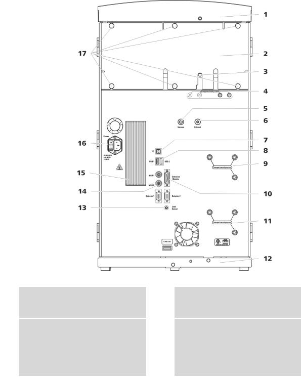
2.2Rear
Figure 2 Rear
1Bottle holder
Offers space for the eluent bottle and additional accessories.
3Drainage tubing connection
For connecting the drainage tubing, which guides escaped liquids away from the detector chamber.
2Back panel
Removable. Enables access to the detector chamber.
4Transport locking screws
For securing the vacuum pump(s) when transporting the instrument. Up to two vacuum pumps can be installed in an instrument. Only two transport locking screws are used if just one vacuum pump is installed.
940 Professional IC Vario ONE/SeS/PP/Prep 1 (2.940.1510) |
9 |

2.3 Feed-throughs for capillaries and cables
5Vacuum connection
For connecting an Extension Module that has a degasser but not its own vacuum pump. This connection has to be firmly sealed with a stopper when not in use.
7PC connection socket
For connecting the instrument to the computer with the USB cable (6.2151.020).
9Transport locking screws
For securing the high-pressure pump (in the middle plug-in) when transporting the instrument.
11Transport locking screws
For securing the high-pressure pump (in the bottom plug-in) when transporting the instrument. These screws are only installed if a plug-in with a high-pressure pump is used in the bottom slot.
13Leak sensor connection socket
Labeled Leak Sensor. For connecting the leak sensor connection cable coiled up in the base tray.
15Cooler
For cooling the power supply unit. May become hot!
17Knurled screws
For fastening the removable back panel.
6Exhaust opening
Labeled Exhaust. For extracting the air from the vacuum chamber.
8USB connection sockets
Labeled USB 1 and USB 2. For connecting USB devices.
10Extension Module connection socket
Labeled Extension Module. For connecting the cable (6.2156.060) used for connecting the instrument to the Extension Module.
12Base tray
With leak sensor and leak sensor cable.
14MSB connection sockets
Labeled MSB 1 and MSB 2. For connecting MSB devices.
16Power socket
Power socket for connecting the power cable and power switch for switching the instrument on and off.
2.3Feed-throughs for capillaries and cables
Multiple openings are available for leading capillaries into the instrument and for leading capillaries and cables out of the instrument:
Openings on the door (see Figure 3, page 11)
Openings on the back panel
Ducts between the instrument and the base tray as well as between the instrument and the bottle holder (see Figure 5, page 13)
10 |
940 Professional IC Vario ONE/SeS/PP/Prep 1 (2.940.1510) |
|
2 Overview of the instrument |
Openings on the door
Figure 3 Feed-throughs on the door
1 |
Luer connector |
|
2 |
Opening for capillaries |
|
For connecting a capillary from inside and |
|
|
For up to 3 capillaries. |
|
for inserting a syringe (6.2816.020) from |
|
|
|
|
outside. For manual sample injection. |
|
|
|
|
|
|
|
|
An opening for up to 3 capillaries is located on the door of the instrument.
The two Luer connections above are not actually openings; the capillaries are fastened to the Luer connection from within using PEEK pressure screws. You can use a syringe to inject or draw out liquid from the outside.
940 Professional IC Vario ONE/SeS/PP/Prep 1 (2.940.1510) |
11 |
2.3 Feed-throughs for capillaries and cables |
|
Openings on the back panel
Figure 4 Openings for capillaries and cables
1 |
Openings for capillaries |
|
2 |
Openings for cables |
|
|
|
|
|
The removable back panel is outfitted with openings through which capillaries and cables can be lead out of the detector chamber.
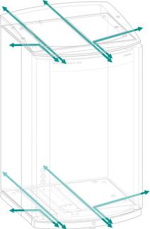
Ducts for capillaries
There are ducts for capillaries between the instrument and base tray as well as between the instrument and the bottle holder. The capillaries can be fed to the front of the instrument from both sides of the instrument and from the front of the instrument to the back of the instrument.
12 |
940 Professional IC Vario ONE/SeS/PP/Prep 1 (2.940.1510) |
|
2 Overview of the instrument |
Figure 5 Ducts for capillaries
940 Professional IC Vario ONE/SeS/PP/Prep 1 (2.940.1510) |
13 |

3.1 Setting up the instrument |
|
3 Installation
3.1Setting up the instrument
3.1.1Packaging
The instrument is supplied in highly protective special packaging together with the separately packed accessories. Keep this packaging, as only this ensures safe transportation of the instrument.
3.1.2Checks
Immediately after receipt, check whether the shipment has arrived complete and without damage by comparing it with the delivery note.
3.1.3Location
The instrument has been developed for operation indoors and may not be used in explosive environments.
Place the instrument in a location of the laboratory which is suitable for operation, free of vibrations, protected from corrosive atmosphere, and contamination by chemicals.
The instrument should be protected against excessive temperature fluctuations and direct sunlight.
3.2Capillary connections in the IC system
Generally speaking, capillary connections between two components of an IC system are made up of one connection capillary and two pressure screws used to connect the capillary to the respective components.
Pressure screws
Three types of pressure screws are used in the IC system:
Number |
Designation |
Use |
|
|
|
6.2744.010 / 6.2744.014 |
Pressure screw |
On the injection valve |
|
|
|
6.2744.070 |
Pressure screw, short |
High-pressure pump, purge |
|
|
valve, inline filter, pulsation |
|
|
absorber, separation columns |
|
|
|
6.2744.090 |
Pressure screw, long |
MCS, sample degasser, 12- |
|
|
port valve |
Pressure screws are tightened and loosened by hand. A tool is not needed.
14 |
940 Professional IC Vario ONE/SeS/PP/Prep 1 (2.940.1510) |

|
|
|
|
3 Installation |
|
|
Also see: PEEK pressure screws video on the Internet http://ic- |
||||
|
help.metrohm.com/maintenance.php?chapter=1_2. |
||||
|
Connection capillaries |
||||
|
PEEK capillaries and PTFE capillaries are used in the IC system. |
||||
PEEK capillaries (poly- |
PEEK capillaries are temperature-resistant up to 100 °C, stable under pres- |
||||
etheretherketone) |
sure up to 400 bar (depending on the inner diameter), flexible, chemically |
||||
|
inert and have an extremely smooth surface. They can be readily cut down |
||||
|
to the desired length with the capillary cutter (6.2621.080). |
||||
|
Use: |
||||
|
PEEK capillaries with an inner diameter of 0.25 mm (6.1831.010) for |
||||
|
|
the entire high-pressure section. |
|||
|
PEEK capillaries with an inner diameter of 0.75 mm (6.1831.030) for |
||||
|
|
sample processing in the ultratrace range. |
|||
PTFE capillaries |
PTFE capillaries are transparent and enable visual tracing of the liquids to |
||||
(poly(tetrafluoroethy- |
be pumped. They are chemically inert, flexible and temperature-resistant |
||||
lene)) |
up to 80 °C. They can be readily cut down to the desired length with the |
||||
|
capillary cutter (6.2621.080). |
||||
|
Use: |
||||
|
PTFE capillaries (6.1803.0x0) are used for the low-pressure section. |
||||
|
PTFE capillaries with an inner diameter of 0.5 mm for sample process- |
||||
|
|
ing. |
|||
|
PTFE capillaries with an inner diameter of 0.97 mm for sample process- |
||||
|
|
ing and rinsing solutions (they are not necessarily included in the scope |
|||
|
|
of delivery of the instrument). |
|||
|
Capillary connections |
||||
|
|
|
|
|
|
|
|
|
NOTE |
||
|
|
|
|||
|
|
|
|
|
|
|
If you work with an increased system pressure (> 15 MPa), capillaries |
||||
|
may slip out of the pressure screws. |
||||
|
To avoid this, we recommend degreasing the ends of the capillaries |
||||
|
before installing them. |
||||
|
Dampen a cloth with acetone and wipe off the ends of the capillaries |
||||
|
before connecting them with the pressure screws. |
||||
|
|
|
|
|
|
|
In order to achieve optimum analysis results, capillary connections in an IC |
||||
|
system must be absolutely tight and free of dead volume. Dead volume |
||||
|
occurs if two capillary ends connected to each other do not fit exactly, |
||||
|
thus allowing liquid to escape. There are two possible causes for this: |
||||
940 Professional IC Vario ONE/SeS/PP/Prep 1 (2.940.1510) |
15 |

3.2 Capillary connections in the IC system |
|
The capillary ends do not have exactly flat edges.
The two capillary ends do not completely meet.
One prerequisite for dead-volume-free capillary connection is that both capillary ends are cut exactly flat. Therefore we recommend cutting PEEK capillaries only with a capillary cutter (6.2621.080).
Also see: Cutting capillaries video on the Internet http://ichelp.metrohm.com/maintenance.php?chapter=1_1.
Creating dead-volume-free capillary connections
To create dead-volume-free capillary connections, proceed as follows:
1Wipe off the end of the capillary with a cloth dampened with acetone.
2Slide the pressure screw over the capillary. Ensure that the capillary protrudes 1 to 2 mm from the tip of the pressure screw.
3Push the capillary into the connection or coupling as far as it will go and hold it there.
4 Only then start turning the pressure screw.
Colored sleeves for PEEK capillaries
The enclosed set of varicolored sleeves for PEEK capillaries (6.2251.000) serves to easily differentiate the various flows of liquid in the system through color coding. Each capillary conveying a given liquid (e.g. eluent) can be marked with sleeves of the same color.
1Slide a sleeve of a selected color over a capillary and move it to an easily visible position.
2Heat the colored sleeve, such as with a hairdryer.
The colored sleeve shrinks and adapts to the shape of the capillary.
NOTE
In order to arrange capillaries more clearly, they can be bundled with the spiral band (6.1815.010).
16 |
940 Professional IC Vario ONE/SeS/PP/Prep 1 (2.940.1510) |
|
3 Installation |
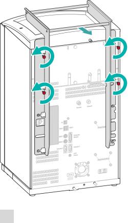
3.3Removing the handle
|
The instrument is equipped with a handle in order to make it easier to |
|
transport. The handle can be removed once the instrument is in place in |
|
the lab. |
Accessories |
You do not need any accessories for the following work steps. |
|
|
|
Removing the handle |
|
|
1Removing the handle
Unscrew the four knurled screws.
Remove the handle.
940 Professional IC Vario ONE/SeS/PP/Prep 1 (2.940.1510) |
17 |
3.4 Removing transport locking screws |
|
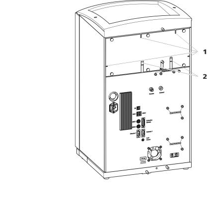
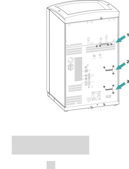
3.4Removing transport locking screws
|
To avoid damage to the drives for the high-pressure pump and the vac- |
|
uum pump during transport, the pumps are secured with transport lock- |
|
ing screws. These are located at the rear of the instrument and labeled |
|
with Transport security screws. |
|
Remove these transport locking screws before the initial start-up. |
Accessories |
For this step you need: |
|
Hex key 4 mm (6.2621.030) |
|
|
|
Remove the transport locking screws |
|
|
Figure 6 Removing the transport locking screws
1 |
Transport locking screws |
|
2 |
Transport locking screws |
|
For the vacuum pump. |
|
|
For the high-pressure pump. |
|
|
|
|
|
3Transport locking screws
For an additional high-pressure pump in the bottom drawer.
1 Remove all of the transport locking screws with the hex key.
18 |
940 Professional IC Vario ONE/SeS/PP/Prep 1 (2.940.1510) |

|
3 Installation |
Store the transport locking screws in a safe place. Reinsert the transport locking screws each time you transport the instrument a significant distance.
CAUTION
The pumps may be damaged if you transport the instrument without inserting the transport locking screws.
3.5Connecting the drainage tubing and leak sensor
The leak sensor detects leaking liquid that collects in the instrument's base tray. Liquid that leaks in the bottle holder or in the detector chamber is routed to the base tray using drainage tubing and is detected there.
If the leak sensor detects a leak in the IC system, the IC instrument is switched off and a warning is output in the software.
The leak sensor functions properly only if the following preconditions are met:
The drainage tubing is connected.
The leak sensor connection cable is inserted into the leak sensor connection socket.
The 940 Professional IC Vario is switched on.
The leak sensor is switched to active in the software.
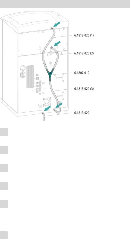
3.5.1Installing the drainage tubing
Liquid that leaks in the bottle holder or detector chamber flows to the rear of the instrument and is drained through openings on the bottle holder and in the detector chamber. The drainage tubing has to be mounted at these openings. This drainage tubing guides the leaking liquid to the base tray where the leak sensor is located.
Accessories |
For this step you need the following parts from the accessory kit: Vario/ |
|
|
Flex Basic (6.5000.000): |
|
|
|
2 × silicone tubing (6.1816.020) |
|
|
Y connector (6.1807.010) |
You also need scissors.
940 Professional IC Vario ONE/SeS/PP/Prep 1 (2.940.1510) |
19 |
3.5 Connecting the drainage tubing and leak sensor |
|
Connecting the drainage tubing
1Cut a piece of silicone tubing into three pieces using scissors: 2 × approx. 40 cm and 1 × 20 cm
2Attach one end of the 40 cm long piece to the drainage tubing connection on the bottle holder.
3Attach one end of the 20 cm long piece to the drainage tubing connection on the detector chamber.
4Attach each of the loose ends of both pieces of silicone tubing to one end of the Y connector.
5Attach one end of the second 40 cm long piece to the third end of the Y connector.
Attach the loose end to the right-side drainage tubing connection on the base tray.
6Attach one end of the second piece of silicone tubing to the left-side drainage tubing connection on the base tray.
20 |
940 Professional IC Vario ONE/SeS/PP/Prep 1 (2.940.1510) |
Loading...