


 Loading...
826 pH mobile / 827 pH lab
Manual
8.827.8001EN

Metrohm AG CH-9100 Herisau Switzerland
Phone +41 71 353 85 85 Fax +41 71 353 89 01 info@metrohm.com www.metrohm.com
826 pH mobile / 827 pH lab
Program version 5.826.0011 and 5.827.0011
Manual
8.827.8001EN |
12.2010 jb/ebe |
Teachware Metrohm AG CH-9100 Herisau
teachware@metrohm.com
This documentation is protected by copyright. All rights reserved.
Although all the information given in this documentation has been checked with great care, errors cannot be entirely excluded. Should you notice any mistakes please send us your comments using the address given above.
Documentation in additional languages can be found on
http://documents.metrohm.com.

|
|
|
|
Contents |
|
Table of contents |
|
|
|||
1 |
Introduction.......................................................... |
1 |
|
||
|
1.1 |
Instrument description................................................................................. |
1 |
|
|
|
1.2 |
Parts and controls........................................................................................ |
2 |
|
|
|
1.3 |
Information about these Instructions for Use ............................................. |
4 |
|
|
|
|
1.3.1 |
Notation and pictograms ......................................................................... |
4 |
|
|
1.4 |
Safety information ........................................................................................ |
5 |
|
|
|
|
1.4.1 |
Electrical safety ........................................................................................ |
5 |
|
|
|
1.4.2 |
General handling rules ............................................................................. |
5 |
|
2 |
Installation........................................................... |
7 |
|
||
|
2.1 |
Instrument setup .......................................................................................... |
7 |
|
|
|
|
2.1.1 |
Packaging ................................................................................................. |
7 |
|
|
|
2.1.2 |
Checks ...................................................................................................... |
7 |
|
|
|
2.1.3 |
Location .................................................................................................... |
7 |
|
|
2.2 |
Inserting the batteries at 826 pH mobile ..................................................... |
7 |
|
|
|
2.3 |
Connecting the electrodes and sensors ..................................................... |
7 |
|
|
|
2.4 |
Mains connection ......................................................................................... |
8 |
|
|
|
2.5 |
Switch on...................................................................................................... |
8 |
|
|
|
2.6 |
Connecting a printer .................................................................................... |
9 |
|
|
|
2.7 |
Initial configuration ...................................................................................... |
9 |
|
|
3 |
Operation ........................................................... |
11 |
|
||
|
3.1 |
Operating concept ..................................................................................... |
11 |
|
|
|
3.2 |
All key functions at a glance...................................................................... |
12 |
|
|
|
3.3 |
Operating principles .................................................................................. |
14 |
|
|
|
|
3.3.1 Configuration and method parameters ................................................. |
14 |
|
|
|
|
3.3.2 |
Editing menu entries .............................................................................. |
14 |
|
|
|
3.3.3 Entering text and numbers ..................................................................... |
15 |
|
|
4 |
Short operating tutorial ..................................... |
17 |
|
||
|
4.1 |
Requirements ............................................................................................. |
17 |
|
|
|
4.2 |
pH calibration ............................................................................................. |
17 |
|
|
|
4.3 |
pH measurement........................................................................................ |
19 |
|
|
5 |
Configuration ..................................................... |
21 |
|
||
|
5.1 |
Report |
......................................................................................................... |
21 |
|
|
5.2 |
Printing out measured values.................................................................... |
22 |
|
|
|
5.3 |
Storing ...........................................................................measured values |
25 |
|
|
|
5.4 |
Auxiliaries................................................................................................... |
26 |
|
|
6 |
Methods ......................................./ Parameters |
29 |
|
||
|
6.1 |
pH measurement .....................................................................(pH mode) |
29 |
|
|
|
|
6.1.1 ........................................................................... |
Measuring parameters |
29 |
|
|
|
6.1.2 ........................................................................... |
Calibration parameters |
30 |
|
|
|
6.1.3 ...................................................................................................... |
Limits |
32 |
|
|
|
6.1.4 ................................................................................. |
pH calibration data |
33 |
|
826/827 pH meter, Instructions for Use |
|
I |
|||

Contents
|
6.2 |
Temperature measurement (T mode)........................................................ |
34 |
|
|
6.3 |
Potential measurement (U mode).............................................................. |
34 |
|
7 |
Various functions ............................................... |
35 |
||
|
7.1 |
Reports |
....................................................................................................... |
35 |
|
|
7.1.1 |
Arrangement of a report ......................................................................... |
36 |
|
|
7.1.2 |
Report identification ............................................................................... |
36 |
|
|
7.1.3 ........................................................................... |
Measuring point report |
37 |
|
|
7.1.4 ................................................................................... |
Calibration report |
37 |
|
|
7.1.5 ............................................................................... |
Configuration report |
37 |
|
|
7.1.6 .................................................................................... |
Parameter report |
38 |
|
|
7.1.7 ........................................................... |
Measured values memory report |
38 |
|
|
7.1.8 ....................................................................................... |
PC/LIMS report |
38 |
|
|
7.1.9 .................................................................................. |
System test report |
39 |
|
7.2 |
Measured ..........................................................................values memory |
40 |
|
|
|
7.2.1 .......................................................................... |
Store measured values |
40 |
|
|
7.2.2 ........................................................................... |
Print measured values |
40 |
|
|
7.2.3 .......................................................................... |
Show measured values |
40 |
|
7.3 |
Setup .......................................................................................................... |
|
42 |
|
|
7.3.1 ................................................................................................... |
Locking |
42 |
8 Troubleshooting .....– Messages – Maintenance |
43 |
|||
|
8.1 |
Troubleshooting......................................................................................... |
43 |
|
|
8.2 |
Messages ................................................................................................... |
45 |
|
|
8.3 |
Diagnosis ................................................................................................... |
47 |
|
|
8.4 |
Maintenance............................................................................................... |
49 |
|
|
|
8.4.1 ......................................................... |
Changing the batteries (826 only) |
49 |
|
|
8.4.2 ......................................................... |
Changing the batteries (827 only) |
50 |
9 |
Appendix............................................................. |
51 |
||
|
9.1 |
Technical ............................................................................................data |
51 |
|
|
|
9.1.1 .................................................................................. |
Measuring modes |
51 |
|
|
9.1.2 .................................................................................... |
Measuring inputs |
51 |
|
|
9.1.3 .............................................................. |
Measuring input specifications |
52 |
|
|
9.1.4 ..................................................................... |
Measured values memory |
52 |
|
|
9.1.5 .................................................................................................... |
Display |
52 |
|
|
9.1.6 ................................................................................................ |
Interfaces |
52 |
|
|
9.1.7 .......................................................................................... |
Power supply |
52 |
|
|
9.1.8 ........................................................................... |
Housing specifications |
52 |
|
|
9.1.9 .............................................................................. |
Safety specifications |
53 |
|
|
9.1.10 .................................................... |
Electromagnetic compatibility (EMC) |
53 |
|
|
9.1.11 ............................................................................. |
Ambient temperature |
53 |
|
|
9.1.12 ............................................................................. |
Reference conditions |
53 |
|
|
9.1.13 ............................................................................................ |
Dimensions |
53 |
|
9.2 |
Menu structures ......................................................................................... |
55 |
|
|
|
9.2.1 ........................................................................ |
Instrument configuration |
55 |
|
|
9.2.2 ................................................................... |
Parameters in the pH mode |
56 |
|
|
9.2.3 ...................................................................... |
Parameters in the T mode |
56 |
|
|
9.2.4 ..................................................................... |
Parameters in the U mode |
56 |
|
9.3 |
Stored buffer ...................................................................................series |
57 |
|
II |
826/827 pH meter, Instructions for Use |

|
|
|
Contents |
9.4 |
Scope of delivery ....................................................................................... |
62 |
|
|
9.4.1 |
826 pH mobile ........................................................................................ |
62 |
|
9.4.2 |
Optional accessories for 826 pH mobile ............................................... |
65 |
|
9.4.3 |
827 pH lab .............................................................................................. |
65 |
|
9.4.4 |
Optional accessories for 827 pH lab ..................................................... |
67 |
9.5 |
Warranty and conformity ........................................................................... |
68 |
|
|
9.5.1 |
Warranty.................................................................................................. |
68 |
|
9.5.2 |
Declaration of Conformity ...................................................................... |
69 |
|
9.5.3 |
Declaration of Conformity ...................................................................... |
70 |
|
9.5.4 |
Quality Management Principles ............................................................. |
71 |
10 Index................................................................... |
|
73 |
|
826/827 pH meter, Instructions for Use |
III |

Contents
List of illustrations |
|
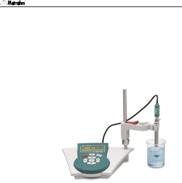
Fig. 1: pH meter 827 .................................................................................................................. |
1 |
Fig. 2: Front view of the 827 pH lab........................................................................................... |
2 |
Fig. 3: Rear view of the 827 pH lab ........................................................................................... |
3 |
Fig. 4: Connecting sensors........................................................................................................ |
8 |
Fig. 5: Changing the batteries for the 826 pH mobile............................................................. |
49 |
Fig. 6: Changing the batteries for the 827 pH lab................................................................... |
50 |
IV |
826/827 pH meter, Instructions for Use |
1 Introduction
1 Introduction
These instructions provide you with a comprehensive overview of the installation, working principles and operation of the 826 pH mobile and
827 pH lab.
Additional theoretical principles can be found in the Metrohm Monograph 8.015.5013 "Electrodes in Potentiometry".
You can also request our descriptions of applications involving pH measurements in the form of Application Notes and Application Bulletins from your local Metrohm agency or download them from the Internet under www.metrohm.com.
Fig. 1: pH meter 827
1.1Instrument description
Both instrument versions, the portable 826 pH mobile and the laboratory device 827 pH lab, are used for measuring pH, temperature and potential reliably. The functional range is identical. The pH meter 826 pH mobile is operated with batteries whereas the 827 pH lab has got an external power supply.
Up to 200 values can be stored in the memory together with the most important additional data; these can be viewed and printed as a report.
All stored information (measured values, configuration, parameters, etc.) can be transmitted via the infrared interface to a printer or computer for output as a report.
826/827 pH meter, Instructions for Use |
1 |

1.2 Parts and controls
Both instruments have the following features:
•Dot-matrix display for both the continuous display of the measured value and for showing the user dialog.
•High-impedance measuring input for pH, redox or ISE sensors, a connection for a separate reference electrode and an input for temperature sensors (NTC or Pt1000).
•Infrared interface for a infrared printer.
1.2Parts and controls
|
Fig. 2: Front view of the 827 pH lab |
||
|
|
|
|
1 LCD display |
|
|
3 Input and navigation keys |
|
|
|
Menu selection, text and number input |
2On/Off key
Key for switching the instrument on and off
2 |
826/827 pH meter, Instructions for Use |
1 Introduction
Fig. 3: Rear view of the 827 pH lab
4Connection for potentiometric electrodes
pH, ISE, redox or silver electrodes with built-in or separate reference electrode; socket type F
5Connection for separate reference electrode
for connection with two 2 mm B-plugs; the adapter 6.2103.180 or 6.2103.190 is necessary with 4 mm banana plugs
6Connection for temperature sensor
Pt1000 or NTC, for connection with two 2 mm B-plugs; the adapters 6.2103.180 and 6.2103.190 are necessary with 4 mm banana plugs; red plug in socket "Temp."!
7Infrared interface
Connection for printer or PC with infrared interface
86 V power connection with 827 pH lab only
826/827 pH meter, Instructions for Use |
3 |
1.3 Information about these Instructions for Use
1.3Information about these Instructions for Use
Attention!
Please study these instructions carefully before you start to use the instrument. The instructions contain information and warnings that must be observed by the user in order to guarantee the safe use of the instrument.
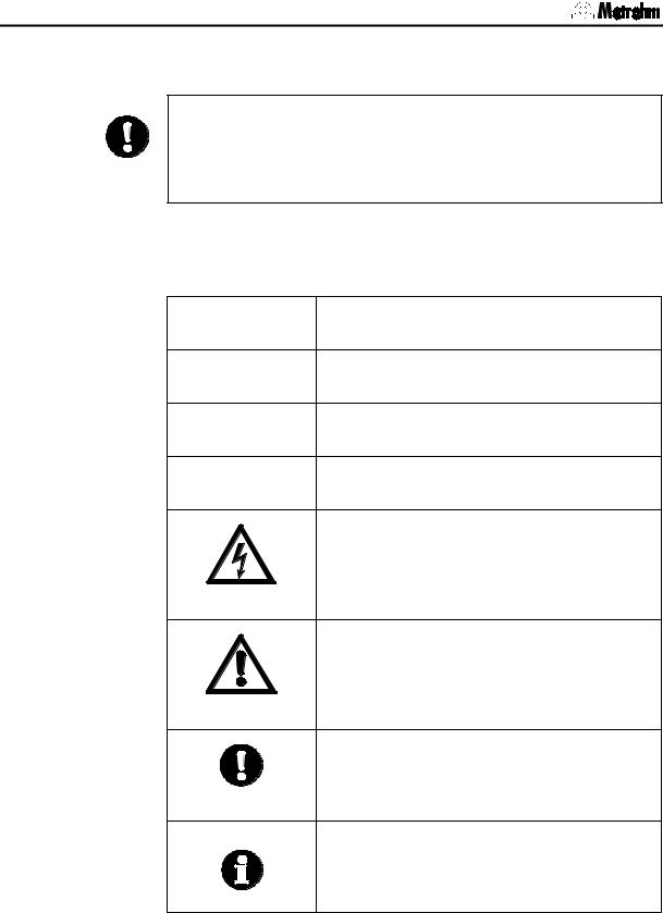
1.3.1Notation and pictograms
The following notations and pictograms (symbols) are used in these instructions:
Parameter Menu item, parameter or input value
<< config >> |
Menu |
<OK> Key
4Operating element
Danger
This symbol indicates a possible risk of death or injury if the given information is not properly observed.
Warning
This symbol indicates a possible risk of damage to the instrument or its components if the given information is not properly observed.
Attention
This symbol indicates important information.
Please read it carefully before you continue.
Information
This symbol indicates additional information and tips.
4 |
826/827 pH meter, Instructions for Use |
1 Introduction
1.4Safety information
Warning!
This instrument should only be used in accordance with the information given in these installation instructions.
1.4.1Electrical safety
Please observe the following guidelines:
•Only qualified Metrohm technicians should carry out service work on electronic components.
•Open the housing only in order to change the batteries. There are no components inside the housing that the user can service or exchange. The changing of the batteries is described in Section 8.4.
Electrical safety when handling the pH meter is guaranteed within the framework of the IEC 61010-1 Standard. The following points must be observed:
Danger!
Please make sure that the external power supply is always kept dry.
Protect it against direct liquid contact.
Warning!
Electronic components are sensitive to electrostatic charges and can be destroyed by a discharge. Always switch off the pH meter before making or breaking electrical connections on the rear panel of the instrument.
1.4.2General handling rules
Handling solutions
Warning!
When working with water or other solutions in the immediate vicinity of the pH meter please avoid excessive liquid splashes on the instrument housing or power supply. Any such splashes must be removed as quickly as possible in order to prevent the liquid from entering the instrument or the power supply.
Do not clean the plexiglass display with organic solvents like e. g. acetone.
826/827 pH meter, Instructions for Use |
5 |

1.4 Safety information
6 |
826/827 pH meter, Instructions for Use |

2 Installation
2 Installation
2.1Instrument setup
2.1.1Packaging
The 826/827 pH meter and its specially packed accessories are supplied in very protective special packaging. Please store this packaging in a safe place; it is the only way in which the safe transport of the instrument can be guaranteed.
2.1.2Checks
Please check that the delivery is complete and undamaged immediately on receipt (compare with delivery note and list of accessories given in
Section 9.4).
2.1.3Location
Place the instrument on a suitable vibration-free laboratory bench, protected from corrosive atmospheres and contact with chemicals.
2.2Inserting the batteries at 826 pH mobile
The 826 pH mobile is delivered without inserted batteries. Inserting the batteries is described in Section 8.4.1.
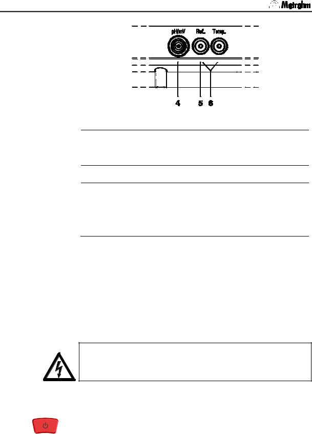
2.3Connecting the electrodes and sensors
On its rear panel the 826/827 pH meter has connections for a potentiometric electrode 4, a separate reference electrode 5 and a temperature sensor 6.
Connect your electrodes and sensors according to the following diagram to the switched off pH meter:
826/827 pH meter, Instructions for Use |
7 |
2.4 Mains connection
Fig. 4: Connecting sensors
4Connection for potentiometric electrodes
pH, ISE, redox or silver electrodes with built-in or separate reference electrode; plug F
5Connection for separate reference electrode
6Connection for temperature sensor
Pt1000 or NTC, connected via two 2 mm banana plugs, reducing adapters for 4 mm plug B may be necessary (6.2103.180 / 6.2103.190). Please observe: The red plug must be put in the socket "Temp." for shielding purposes!
2.4Mains connection
The 827 pH lab has an external power supply providing 6 V (DC). This is connected to 6 V mains connection 8.
The following power supply units are available:
•6.2161.010 power supply unit EU 230 V / 6 V DC
•6.2161.020 power supply unit US 115 V/ 6 V DC
•6.2161.030 power supply unit UK 230 V / 6 V DC
•6.2161.040 power supply unit AUS 240 V / 6 V DC
Attention!
Please make sure that the power supply is always kept dry. Protect it against direct liquid contact.
2.5Switch on
Switch on the pH meter with the < > key. The instrument will start in the last operating mode to have been used for measuring pH, temperature or potential.
During the switch-on process an instrument checking routine is carried out automatically. If an error message is displayed here ('Err x') then please contact your local Metrohm agency.
8 |
826/827 pH meter, Instructions for Use |
2 Installation
2.6Connecting a printer
A printer with an infrared interface can be connected to the infrared interface for printing out reports.
Activate the infrared interface of the pH meter under configuration/auxil/IR interface: (see Section 5.4) No further transmission parameters need to be set.
Attention!
In order to guarantee a perfect transmission the distance between the pH meter and the printer should be 80 cm at the maximum. The infrared interfaces must face each other directly. Never expose the infrared interface to direct sunlight.
2.7Initial configuration
The pH meter is delivered with standard settings for the configuration. If it should ever be necessary to reset the configuration of the instrument to its original condition then this can be carried out by a re-initialization of the instrument memory (see Section 8.3).
Before you start to make measurements please change the following configuration settings. If you first want to make yourself familiar with the operation of the pH meter then please read Sections 3.1 to 3.3. More detailed explanations of the individual configuration settings are given in Section 5.
Date and time
configuration/auxil/date and /time
Please check that the date and time are correct.
Temperature sensor
configuration/auxil/temp.sens.
Enter the type of temperature sensor that is connected. If no temperature sensor is connected and you always want to enter the measuring temperature manually then you can ignore this setting.
826/827 pH meter, Instructions for Use |
9 |

2.7 Initial configuration
10 |
826/827 pH meter, Instructions for Use |
3 Operation
3 Operation
3.1Operating concept
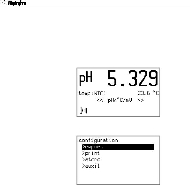
The pH meter provides two types of display:
1.The measured value display.
This is the normal instrument display.
2.The menu display
This is used for editing various settings.
In the measured value display the current measured value is shown together with the method of the temperature measurement (only for mode pH) and the date and time (only for modes U and T) respectively. The measured value display changes when the operating mode of the pH meter is changed with <OK> in the menu << pH/°C/mV >>. You can easily see which mode is set from the measuring unit or the prefix "pH" shown in the display.
826/827 pH meter, Instructions for Use |
11 |
3.2 All key functions at a glance
3.2All key functions at a glance
The functions of all the keys are described below both for the measured value display and the menu display:
Key |
Measured value display |
Menu display |
||
|
|
|
||
|
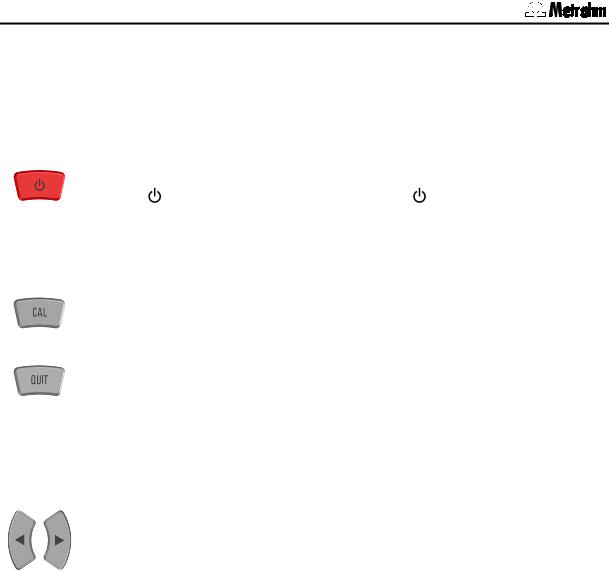
On/Off |
On/Off |
||
|
• |
The < > key switches the instru- |
• |
The < > key switches the instru- |
|
|
ment on and off. |
|
ment off at any time. |
|
• |
After switching-on the pH meter is in |
|
|
|
|
the initial state of the last mode to |
|
|
|
|
have been used. |
|
|
|
|
|
|
|
|
Starting calibration |
|
|
|
|
• |
The <CAL> key starts the pH cali- |
|
|
|
|
bration (in mode pH only). |
|
|
|
|
|
||
|
Acknowledging messages |
Canceling working step |
||
|
• |
Displayed messages are normally |
• |
In menus <QUIT> causes a jump |
|
|
acknowledged with <QUIT> (Ex- |
|
to the next higher level without ac- |
|
|
ceptions: see Section 8.2). |
|
cepting the alterations. |
|
• |
If the cause of the message has not |
|
|
|
|
been remedied, then it will appear |
|
|
|
|
again at the next check. |
|
|
|
|
|
||
|
Menu selection |
Selecting predefined entries |
||
|
• |
The menu is being changed with the |
• |
For menu parameters which offer a |
|
|
arrow keys <> and <>. |
|
fixed choice of settings (recogniza- |
|
|
|
|
ble by the final colon) the selection |
|
|
|
|
list can be viewed with the arrow |
|
|
|
|
keys. The arrow determines the se- |
|
|
|
|
lection direction. |
|
|
|
Cursor control for text input |
|
|
|
|
• |
The cursor is moved to that position |
|
|
|
|
which needs to be altered. |
|
|
|
|
|
12 |
826/827 pH meter, Instructions for Use |
|
|
|
|
|
3 Operation |
|
|
|
|
||
|
Key |
Measured value display |
Menu display |
||
|
|
|
|
||
|
|
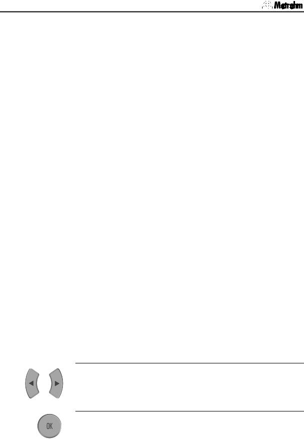
Altering display contrast |
Controlling the menu bar |
||
|
|
• |
The contrast of the LCD display can |
• |
In each menu display the <> und |
|
|
|
be altered with the arrow keys <> |
|
<> keys can be used to move the |
|
|
|
and <> during the measured val- |
|
selection bar up and down by one |
|
|
|
ue display. |
|
line. |
|
|
• This setting is retained after the in- |
Cursor control for text input |
||
|
|
|
strument has been switched off and |
• |
The character to be entered is se- |
|
|
|
on. The default value is only reset af- |
|
lected with the arrow keys and en- |
|
|
|
ter the memory has been initialized. |
|
tered with <OK>. |
|
|
|
|
Leafing through the measured value |
|
|
|
|
|
memory |
|
|
|
|
|
• |
Leafing through between the entries |
|
|
|
|
|
in the measured value memory dis- |
|
|
|
|
|
play: starting from the last measured |
|
|
|
|
|
value having been stored you can |
|
|
|
|
|
access older entries with <> and |
|
|
|
|
|
vice versa. |
|
|
|
|
||
|
|
Calibration |
Confirming entry |
||
|
|
• |
The calibration sequence is contin- |
• |
The <OK> key is used to complete |
|
|
|
ued with <OK>. |
|
each entry with the selection bar |
|
|
• |
The calibration data are accepted |
|
moving on to the next parameter. If |
|
|
|
an entry is exited without this confir- |
||
|
|
|
with <OK> in case they are out of |
|
|
|
|
|
|
mation then the entered value will be |
|
|
|
|
the defined limits. |
|
|
|
|
|
|
rejected. |
|
|
|
|
|
|
|
|
|
|
|
|
|
826/827 pH meter, Instructions for Use |
13 |
3.3 Operating principles
3.3Operating principles
3.3.1Configuration and method parameters
Instrument configuration and parameters for the pH mode (no adjustable parameters are required for the measuring modes U (mV) and T (°C)) are each contained in menus with a tree structure. These menu structures are shown in the appendix in Section 9.2.
The instrument configuration of the pH meter is described in the menu
<<config >>. This contains the basic settings that apply for all measuring modes. The parameters for the pH mode are stored in the menu
<<param >>.
The change from the measured value display to the menu display is made by selecting the corresponding menu and confirming with the <OK> key. The title of the submenu appears first, and is shown with an '>' (e. g. >report). You can now move the selection bar up and down with the <> and <> arrow keys. Each underlying level in the menu structure is opened with <OK> and exited with <QUIT>. Alterations to individual entries must be confirmed with <OK>. If such alterations are exited with <QUIT> then they remain ineffective.
If an entry is confirmed with <OK> then the selection bar will move to the next entry. At the end of a submenu it will finally change to the next point of the superior menu selection.
In this way you can run through the complete menu structure for the configuration and parameters by repeatedly pressing the <OK> key. This can be helpful when carrying out checks.
Not all parts of the menu structure described below are visible in the display at all times. Only the specific possible settings of the option which is currently activated are shown. For example, the various settings for printing under configuration/print/print crit. are not visible when printing has been deactivated completely (off). If one of the other printing criteria is selected then the particular settings it requires will appear in the display.
3.3.2Editing menu entries
A basic differentiation is made between two types of menu entry.
Entries with a fixed selection are indicated by a colon:
print crit.: immed., time, drift, change, off
The selection is then made with the arrow keys and confirmed with
<OK>.
Entries which can be edited are altered by entering a new value and confirming it with <OK>.
14 |
826/827 pH meter, Instructions for Use |

3 Operation
3.3.3Entering text and numbers
The editing of text and number inputs is activated with the <> or <> key. The first digit of the entry field will be displayed inverted for text entries whereas it is the last digit for number entries. The cursor can be moved to the position to be changed with the <> or <> key.
The desired character can be selected from a cylinder with the <> or <> keys. The cursor movement can be accelerated by keeping the arrow keys pressed down.
The following characters can be selected:
•For ASCII entry fields:
a, b, c, d, e, f, g, h, i, j, k, l, m, n, o, p, q, r, s, t, u, v, w, x, y, z, 0, 1, 2, 3, 4, 5, 6, 7, 8, 9, ., –, empty
•For number entry fields:
0, 1, 2, 3, 4, 5, 6, 7, 8, 9, ., –, empty
The entry is checked for validity and accepted if it is valid. Otherwise the entered value is blinking and it can be corrected. If a space has been entered between two numbers of a number entry, the display is blinking as well. The value can be corrected then or the original value is entered by pressing <QUIT>. The editing can be exited with <QUIT> without storing the setting.
826/827 pH meter, Instructions for Use |
15 |

3.3 Operating principles
16 |
826/827 pH meter, Instructions for Use |
4 Short operating tutorial
4 Short operating tutorial
In this section the necessary steps for carrying out a simple pH and ion measurement with calibration are described. The instructions are limited to those steps that are absolutely necessary and will enable you to carry out your first measurements with the pH meter directly. The operating principles are described in Section 3.3.
4.1Requirements
The following instruments, accessories and solutions are required for carrying out the pH calibration and measurement described below:
•826 pH mobile (2.826.0XX0) or 827 pH lab (2.827.011X,
2.827.021X)
•pH electrode
•Calibration buffers
Metrohm buffer solutions pH 4.00 and pH 7.00
The calibration parameters for the pH mode are set for a calibration using two Metrohm buffers as default (see Section 6.1.2). If you want to use other buffers then the corresponding buffer type must be entered.
4.2pH calibration
1Start calibration with first buffer
•Start calibration with <CAL>
•Immerse pH electrode in buffer solution pH 7 and confirm with
<OK>
•If a temperature sensor is connected, the calibration temperature is being determined
•If no temperature sensor is connected:
enter the temperature with the arrow keys and confirm with
<OK>
•The first buffer is being measured
•The following message is displayed after successful measurement:
 change buffer <OK>
2Continue calibration with second buffer
•Remove pH electrode from first buffer and rinse with water
•Immerse pH electrode in second buffer solution pH 4 and continue calibration sequence with <OK>
•The second buffer is being measured
826/827 pH meter, Instructions for Use |
17 |
Loading...