


 Loading...
CH-9101 Herisau/Switzerland
E-Mail info@metrohm.com
Internet www.metrohm.com
Titrando
Installation Instructions
8.840.1133 |
06.2006 / jb |

Teachware
Metrohm AG Oberdorfstrasse 68 CH-9101 Herisau teachware@metrohm.com
These instructions are protected by copyright. All rights reserved.
Although all the information given in these Instructions has been checked with great care, errors cannot be entirely excluded. Should you notice any mistakes please inform the author at the address given above.

|
|
|
|
Contents |
|
|
|
|
|||
Table of contents |
|
|
|||
1 |
Introduction.......................................................... |
1 |
|
||
|
1.1 |
Instrument description................................................................................... |
2 |
|
|
|
1.2 |
Information about the Installation Instructions............................................ |
3 |
|
|
|
|
1.2.1 |
Organization ............................................................................................. |
3 |
|
|
|
1.2.2 |
Notation and pictograms ......................................................................... |
4 |
|
|
1.3 |
Parts and controls.......................................................................................... |
5 |
|
|
|
1.4 |
Safety notes.................................................................................................... |
8 |
|
|
|
|
1.4.1 |
Electrical safety......................................................................................... |
8 |
|
2 |
Installation ........................................................... |
9 |
|
||
|
2.1 |
Overview ...................................................................................................... |
10 |
|
|
|
2.2 |
Instrument setup ......................................................................................... |
11 |
|
|
|
|
2.2.1 |
Packaging............................................................................................... |
11 |
|
|
|
2.2.2 |
Checks.................................................................................................... |
11 |
|
|
|
2.2.3 |
Location.................................................................................................. |
11 |
|
|
2.3 |
Controller connection ................................................................................. |
11 |
|
|
|
|
2.3.1 |
Touch Control connection...................................................................... |
12 |
|
|
|
2.3.2 |
Computer connection............................................................................. |
13 |
|
|
2.4 |
Device connection at the MSB ................................................................... |
14 |
|
|
|
|
2.4.1 |
Connecting stirrers and titration stands................................................. |
15 |
|
|
|
2.4.2 |
Attaching the exchange unit to the Titrando.......................................... |
16 |
|
|
|
2.4.3 |
Connecting an external dosing device .................................................. |
18 |
|
|
|
2.4.4 |
Connecting a remote box....................................................................... |
20 |
|
|
2.5 |
Device connection at the USB.................................................................... |
21 |
|
|
|
|
2.5.1 |
Connecting a printer............................................................................... |
21 |
|
|
|
2.5.2 |
Connecting a balance ............................................................................ |
22 |
|
|
|
2.5.3 |
Connecting a USB Sample Processor / Robotic Titrosampler.............. |
24 |
|
|
|
2.5.4 |
Connecting additional Titrandos or Dosing Interfaces .......................... |
24 |
|
|
|
2.5.5 |
Connecting a PC keyboard (Titrando with Touch Control only)............ |
25 |
|
|
|
2.5.6 |
Connecting a barcode reader................................................................ |
25 |
|
|
|
2.5.7 |
Connecting a USB hub .......................................................................... |
26 |
|
|
|
2.5.8 |
Connecting a Bluetooth® adapter.......................................................... |
26 |
|
|
2.6 |
Sensor connection ...................................................................................... |
29 |
|
|
|
|
2.6.1 |
Connecting an 854 iConnect ................................................................. |
29 |
|
|
|
2.6.2 |
Differential potentiometry ....................................................................... |
30 |
|
|
|
2.6.3 |
Titration vessel setup.............................................................................. |
30 |
|
|
|
2.6.4 |
Assembly of the Karl Fischer titration cell.............................................. |
31 |
|
|
2.7 |
Update of the instrument software............................................................. |
32 |
|
|
3 |
Troubleshooting ................................................. |
33 |
|
||
|
3.1 |
Problems...................................................................................................... |
33 |
|
|
4 |
Appendix............................................................. |
35 |
|
||
|
4.1 |
Technical data ............................................................................................. |
35 |
|
|
|
|
4.1.1 |
Titration and measuring modes ............................................................. |
35 |
|
|
|
4.1.2 |
Measuring interfaces.............................................................................. |
35 |
|
Titrando Installation Instructions |
|
|
I |
||

Contents
|
4.1.3 |
Specification of the measuring inputs ................................................... |
36 |
|
4.1.4 |
Specification of the measuring inputs (857 only) .................................. |
36 |
|
4.1.5 |
Internal dosing device............................................................................ |
37 |
|
4.1.6 |
Interfaces................................................................................................ |
37 |
|
4.1.7 |
Mains connection................................................................................... |
37 |
|
4.1.8 |
Safety specifications .............................................................................. |
38 |
|
4.1.9 |
Electromagnetic compatibility (EMC) .................................................... |
38 |
|
4.1.10 |
Ambient temperature ............................................................................. |
38 |
|
4.1.11 |
Reference conditions ............................................................................. |
38 |
|
4.1.12 |
Dimensions ............................................................................................ |
39 |
|
4.1.13 |
Recycling and disposal.......................................................................... |
39 |
4.2 |
Standard equipment.................................................................................... |
40 |
|
|
4.2.1 |
808 Titrando ........................................................................................... |
40 |
|
4.2.2 |
809 Titrando ........................................................................................... |
41 |
|
4.2.3 |
835 Titrando ........................................................................................... |
42 |
|
4.2.4 |
836 Titrando ........................................................................................... |
43 |
|
4.2.5 |
841 Titrando ........................................................................................... |
44 |
|
4.2.6 |
842 Titrando ........................................................................................... |
45 |
|
4.2.7 |
857 Titrando ........................................................................................... |
46 |
4.3 Additional instruments and optional accessories .................................... |
47 |
||
|
4.3.1 |
Controller for operating the Titrando...................................................... |
47 |
|
4.3.2 |
Stirrers and titration stands.................................................................... |
47 |
|
4.3.3 |
Titration equipment ................................................................................ |
47 |
|
4.3.4 |
Karl Fischer titration equipment 6.5609.000.......................................... |
48 |
|
4.3.5 |
Dosing devices....................................................................................... |
49 |
|
4.3.6 |
Combined pH electrodes....................................................................... |
50 |
|
4.3.7 |
Combined metal electrodes .................................................................. |
50 |
|
4.3.8 |
Ion-sensitive electrodes and surfactant electrodes............................... |
50 |
|
4.3.9 |
Karl Fischer electrodes .......................................................................... |
51 |
|
4.3.10 |
Reference electrodes ............................................................................. |
51 |
|
4.3.11 |
Temperature sensors ............................................................................. |
51 |
|
4.3.12 |
Cables for electrodes and other accessories........................................ |
52 |
|
4.3.13 |
Communication...................................................................................... |
52 |
|
4.3.14 |
Cables for balances ............................................................................... |
53 |
4.4 |
Warranty and conformity ............................................................................ |
54 |
|
|
4.4.1 |
Warranty ................................................................................................. |
54 |
|
4.4.2 |
Declaration of Conformity for 808 Titrando ........................................... |
55 |
|
4.4.3 |
Declaration of Conformity for 809 Titrando ........................................... |
56 |
|
4.4.4 |
Declaration of Conformity for 835 Titrando ........................................... |
57 |
|
4.4.5 |
Declaration of Conformity for 836 Titrando ........................................... |
58 |
|
4.4.6 |
Declaration of Conformity for 841 Titrando ........................................... |
59 |
|
4.4.7 |
Declaration of Conformity for 842 Titrando ........................................... |
60 |
|
4.4.8 |
Declaration of Conformity for 857 Titrando ........................................... |
61 |
|
4.4.9 |
Quality Management Principles............................................................. |
62 |
5 Index ................................................................... |
|
63 |
|
II |
Titrando Installation Instructions |

|
Contents |
List of illustrations |
|
Fig. 1: The Titrando system ...................................................................................................... |
1 |
Fig. 2: Front view of a Titrando with internal dosing drive........................................................ |
5 |
Fig. 3: Front view of a Titrando for the use of external dosing devices ................................... |
6 |
Fig. 4: Rear view of the Titrando ............................................................................................... |
7 |
Fig. 5: Titrando – Peripheral devices ........................................................................................ |
9 |
Fig. 6: Titrando – Touch Control ............................................................................................. |
12 |
Fig. 7: Titrando – Computer.................................................................................................... |
13 |
Fig. 8: Overview of MSB connections..................................................................................... |
14 |
Fig. 9: Titrando – Stirrer........................................................................................................... |
15 |
Fig. 10: Attaching the exchange unit to the Titrando ............................................................. |
16 |
Fig. 11: Example for connecting a dosing device: Titrando – 800 Dosino ........................... |
18 |
Fig. 12: Example for connecting a dosing device: Titrando – 805 Dosimat......................... |
19 |
Fig. 13: Titrando – Remote box .............................................................................................. |
20 |
Fig. 14: Titrando – Printer........................................................................................................ |
21 |
Fig. 15: Titrando – USB-RS232 box – Balance....................................................................... |
23 |
Fig. 16: Titrando –USB Sample Processor............................................................................. |
24 |
Fig. 17: Titrando – Titrando/Dosing Interface ......................................................................... |
24 |
Fig. 18: Titrando – Sensors..................................................................................................... |
29 |
Fig. 19: Connecting the 854 iConnect.................................................................................... |
29 |
Fig. 20: Recommended arrangement of magnetic stirring bar (1), electrode (2) and |
|
buret tip (3) ................................................................................................................... |
30 |
Fig. 21: Drawing of the KF titration cell 6.5609.000................................................................ |
31 |
Fig. 22: Arrangement of transport tip, buret tip and draw-off tip ........................................... |
32 |
Titrando Installation Instructions |
III |

Contents
IV |
Titrando Installation Instructions |

1 Introduction
1 Introduction
These installation instructions provide you with a comprehensive overview of the installation and specifications of the Titrando system. The Titrando is the centerpiece of the modular Titrando system. Operation is carried out either via a Touch Control with touch-sensitive screen ("stand-alone" titrator) or from a computer via the USB connection and using the PC software PC Control or tiamo.
A Titrando system can integrate several, different devices. With PC Control/Touch Control, up to three control devices (Titrandos, Dosing Interfaces, USB Sample Processors, etc.) can be controlled via USB connection. The tiamo software allows to expand the system with practically any number of control devices. The control devices have three to four MSB connections (MSB = Metrohm Serial Bus), to which peripheral devices can be connected. These are mainly dosing drives (700/800 Dosinos and 685/805 Dosimats), stirrers and titration stands, etc.
Figure 1 shows you the flexibility of the Titrando system. On the left a Titrando is shown with external dosing devices operated by the Touch Control. To the right of it you can see an automation system consisting of a USB Sample Processor, a Titrando with internal dosing drive and a Dosimat operated by the PC Control software.
Fig. 1: The Titrando system
Titrando Installation Instructions |
1 |

1.1 Instrument description
Additional information about the Titrando system can be found on the Internet under www.titrando.com.
Information about specific applications can be found in our "Application Bulletins" and "Application Notes"; these can be obtained free of charge from your local Metrohm agency or downloaded from the Internet under www.metrohm.com. Various monographs on the subjects of titration techniques and electrodes are also available.
1.1Instrument description
The Titrandos differ mainly from the kind of dosing drive. They are equipped either with an internal dosing drive for an exchange unit (type 806 or previous) or for the use of external dosing devices (700 and 800 Dosinos with 807 dosing units).
Common features of the Titrando:
•A connection for Touch Control or for a computer with PC software
PC Control or tiamo.
•Four MSB connections (Metrohm Serial Bus) each controlling one dosing device (Dosimat with exchange unit or Dosino with dosing unit), a stirrer or titration stand and a remote box.
•One or two measuring interfaces. A measuring interface consists of a high-impedance measuring input for pH, redox or ISE sensors, an input for a separate reference electrode, a measuring input for temperature sensors (Pt1000 or NTC) and a measuring input for polarized electrodes.
•Two USB connections allow to connect, for example, a printer, keyboard, barcode reader or additional control devices (USB Sample Processor, Titrando, Dosing Interface, etc.).
2 |
Titrando Installation Instructions |
1 Introduction
1.2Information about the Installation Instructions
Attention!
Please study these Installation Instructions carefully before you start to use the Titrando. The instructions contain information and warnings that must be observed by the user in order to guarantee the safe use of the instrument. Please keep these instructions near the instrument so that they are always to hand when required.
1.2.1Organization
These Installation Instructions for the Titrandos provide you with a comprehensive overview of the installation, startup, troubleshooting and technical specifications of the instruments.
The Installation Instructions are arranged as follows:
Introduction
General description of the instrument, operating elements and safety information
Installation
Installation of the instrument, connection of the peripheral devices and accessories
Troubleshooting
Description of possible errors and how to remedy them
Appendix
Technical data, standard equipment, optional accessories, warranty and declaration of conformity
Index
In order to find the information you require about the Titrando you should either use the Table of contents or the Index.
Titrando Installation Instructions |
3 |
1.2 Information about the Installation Instructions
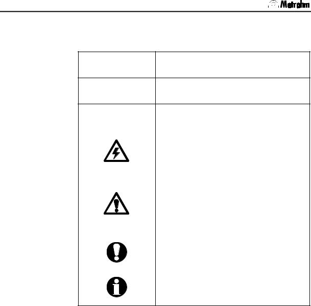
1.2.2Notation and pictograms
The following notation and pictograms are used in these Instructions:
9Control element, instrument element see illustrations in Section 1.3
Instruction
Carry out the instructions step by step.
[Continue] |
Button |
||||
|
|
|
|
|
on the user interface |
|
|
|
|
|
|
|
|
|
|
|
Danger |
|
|
|
|
|
This symbol indicates a possible risk of |
|
|
|
|
|
death or injury to the user and possible |
|
|
|
|
|
damage to the instrument or its compo- |
|
|
|
|
|
nents by electricity. |
|
|
|
|
|
|
|
|
|
|
|
Warning |
|
|
|
|
|
This symbol indicates a possible risk of |
|
|
|
|
|
damage to the instrument or its compo- |
|
|
|
|
|
nents if the given information is not properly |
|
|
|
|
|
observed. |
|
|
|
|
|
|
|
|
|
|
|
Attention |
|
|
|
|
|
This symbol indicates important information |
|
|
|
|
|
that you should read before continuing. |
|
|
|
|
|
|
|
|
|
|
|
Information |
|
|
|
|
|
This symbol indicates additional information |
|
|
|
|
|
and tips that may be particularly useful. |
|
|
|
|
|
|
4 |
Titrando Installation Instructions |
1 Introduction
1.3Parts and controls
Fig. 2: Front view of a Titrando with internal dosing drive
1Guide openings
for centering the exchange unit
2Push rod
of the dosing drive
3Contact pins for the data chip
4Coupling
for switching the flat cock
5"On" LED
Lights up when the Titrando is connected to the mains supply and a controller (Touch Control or computer) is connected and switched on.
6"Status" LED
Shows the current status of the internal dosing drive (see Section 2.4.2).
Titrando Installation Instructions |
5 |

1.3 Parts and controls
Fig. 3: Front view of a Titrando for the use of external dosing devices
7Bottle holder
with holding clips, for two reagent bottles
8"On" LED
Lights up when the Titrando is connected to the mains supply and a controller (Touch Control or computer) is connected and switched on.
6 |
Titrando Installation Instructions |
1 Introduction
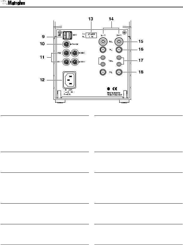
Fig. 4: Rear view of the Titrando
9USB connections USB 1 and USB 2
USB ports (type A) for connection of printer, keyboard, barcode reader, additional Titrandos, USB Sample Processor, etc.
10Controller connection
Connection for Touch Control or PC with installed PC software
11MSB connections MSB 1 to MSB 4
Metrohm Serial Bus
Connection for external dosing device, stirrer or remote box
12Mains connection socket
Mains connection
13Instrument type and serial number
14Measuring interface 1 (Input 1) and Measuring interface 2 (Input 2)
Models 2.8XX.0010: 1 measuring interface,
Models 2.8XX.0020: 2 measuring interfaces
15Connection for reference electrode (Ref.)
e.g. Ag/AgCl reference electrode
16High-impedance measuring input (Ind.)
Connection of pH, redox or ISE sensors with built-in or separate reference electrode
17Connection for temperature sensors (Temp.)
Pt1000 or NTC
18Measuring input for polarized electrodes (Pol.)
e.g. double Pt electrodes
Titrando Installation Instructions |
7 |

1.4 Safety notes
1.4Safety notes
Warning!
This instrument should only be used in accordance with the information given in these installation instructions.
1.4.1Electrical safety
Please observe the following guidelines:
•Only qualified Metrohm technicians should carry out service work on electronic components.
•Do not open the Titrando housing. This could destroy the Titrando. Inside the housing there are no components that the user can service or exchange.
Electrical safety when handling the Titrando is guaranteed within the framework of the IEC 61010 Standard. The following point must be observed:
Protection against electrostatic charges
Warning!
Electronic components are sensitive to electrostatic charges and can be destroyed by a discharge. Always remove the mains cable from the power supply socket before setting up or breaking electrical connections on the rear panel of the instrument.
8 |
Titrando Installation Instructions |

2 Installation
2 Installation
This section describes what you should pay attention to when unpacking and setting up the Titrando. It also informs you about how a complete titration system – from a simple system with stirrer and printer up to a complicated system with additional dosing devices, sample changer and balance – is assembled.
The following illustration provides an overview of the peripheral devices that can be connected to a Titrando:
Fig. 5: Titrando – Peripheral devices
Titrando Installation Instructions |
9 |

2.1 Overview
2.1Overview
The following flow diagram provides an overview of the installation of a simple titration system with stirrer, external dosing device, printer and balance. More detailed information can be found in the given sections.
Setup |
|
Section 2.2 |
|
|
|
|
|
|
|
|
|
Touch Control/Computer connection |
Section 2.3 |
|
|
|
|
|
|
|
|
|
|
Stirrer/Titration stand connection |
Section 2.4.1 |
|
|
|
|
|
|
|
|
|
|
Dosing device connection |
Section 2.4.2 and 2.4.3 |
|
|
|
|
|
|
|
|
|
|
Printer connection |
|
Section 2.5.1 |
|
|
|
|
|
|
|
|
|
Balance connection |
|
Section 2.5.2 |
|
|
|
10 |
Titrando Installation Instructions |

2 Installation
2.2Instrument setup
2.2.1Packaging
The Titrando and the separately packed accessories are delivered in special packaging that provides excellent protection. Please store this packaging in a safe place as no other packaging can guarantee the safe transport of the instrument.
2.2.2Checks
Please check whether the delivery is complete and undamaged immediately on receipt (compare with delivery note and list of accessories given in Section 4.2). If transport damage is evident please refer to the information given in Section 4.4.1.
2.2.3Location
The Titrando was developed for internal laboratory use; it should not be used in explosion-endangered locations.
Place the instrument on a suitable vibration-free laboratory bench, protected as much as possible from corrosive atmospheres and contact with chemicals.
Choose a location where the temperature is usually between +5 °C and +45 °C. The instrument should be protected against excessive variations in temperature and direct sunlight.
2.3Controller connection
Two different methods of controlling the Titrando are available:
•The Touch Control with contact-sensitive screen forms a “standalone” titrator together with the Titrando.
•A computer can be used to control the Titrando by using the PC software PC Control or tiamo.
Attention!
Make sure that the mains cable has been removed from the power supply socket before setting up or breaking connections between the instruments.
Titrando Installation Instructions |
11 |

2.3 Controller connection
2.3.1Touch Control connection
Connect the plug of the Touch Control connection cable to the controller socket.
Fig. 6: Titrando – Touch Control
Note!
The plug is fitted with a "pull-out protection device" that prevents the cable from being pulled out accidentally. When you wish to insert or remove the plug you must first pull back the outer plug sleeves (marked with arrows).
Connect all peripheral devices (see Section 2.4 and 2.5) before you switch on the Touch Control.
Power for the Touch Control is provided by the Titrando.
Connect the Titrando to the mains supply and switch on the Touch Control.
After switch-on automatic system tests are carried out on both the Titrando and the Touch Control. The "On" LED on the Titrando lights up when the system test is finished and the instrument is ready for use.
Attention!
The Touch Control has to be shut down properly with the ON/OFF switch at the back of the instrument before the power supply is interrupted. Otherwise data can be lost. Since the power for the Touch Control is supplied by the Titrando, never disconnect the Titrando from the mains connection (e. g. by switching it off via a mains distributor), before you have switched off the Touch Control.
If you do not want to place the Touch Control directly alongside the Titrando then you can extend the connection between the Titrando and Touch Control with the 6.2151.010 Cable. The connection length must not exceed 5 m.
12 |
Titrando Installation Instructions |

2 Installation
2.3.2Computer connection
Install the PC Control or tiamo software on your computer. Quit the program if you have started it after the installation.
Connect all peripheral devices (see Section 2.4 and 2.5) before you connect the Titrando to the mains supply.
Connect the Titrando to the mains supply. The LED "On" on the Titrando will not yet light up!
Connect the Titrando to a USB connection (type A) on your computer with the 6.2151.000 cable (see the instruction manual for your computer).
Windows 2000: The Titrando will be recognized and the driver will be installed automatically. Windows XP: The Titrando will be recognized and the wizard for the installation of the driver will be started automatically. Select the option "Install the software automatically" and click on [Next]. End the wizard with [Finish].
PC Control
Connect the USB dongle ("authorization plug") supplied with the full version of the PC Control software to any USB socket (type A) of the computer or Titrando.
Windows 2000: The USB dongle will be recognized and the driver will be installed automatically. Windows XP: The USB dongle will be recognized and the wizard for the installation of the driver will be started automatically. Select the option "Install the software automatically" and click on [Next]. End the wizard with [Finish].
Fig. 7: Titrando – Computer
Note!
The plug for connecting to the Titrando is fitted with a "pull-out protection device" that prevents the cable from being pulled out accidentally. When you wish to insert or remove the plug you must first pull back the outer plug sleeves (marked with arrows).
You can extend the connection with a commercially available USB extension cable (type A/m – type A/f). The length of the connection should not exceed 5 m. If you require a longer connection then you must use a commercially available USB signal amplifier. Up to five USB signal am-
Titrando Installation Instructions |
13 |

2.4 Device connection at the MSB
plifiers can be connected in series; this allows a maximum extension of 25 m.
Start the PC Control or tiamo software.
The Titrando will be recognized automatically. When the PC Control or tiamo software is started a system test will be carried out automatically on the Titrando. The LED "On" on the Titrando lights up when the system test is finished and the instrument is ready for use.
2.4Device connection at the MSB
The following devices can be connected via each of the four MSB connections (Metrohm Serial Bus): one stirrer or titration stand, one Dosimat or Dosino dosing device and one remote box. The stirrers and remote boxes each have an MSB output so that the devices can be switched sequentially ("daisy chain"). The following illustration provides an overview of the devices that can be connected to an MSB.
Fig. 8: Overview of MSB connections
The MSB 1 of the Titrando with internal dosing drive is occupied by the internal dosing drive. This means that only a stirrer and a remote box can be connected to MSB 1.
First connect all peripheral devices and then connect the Titrando to the mains supply. MSB connections can be extended with the 6.2151.010 cable. The maximum length of the connection is 15 m.
The Titrando automatically recognizes which device has been connected to which MSB connection. The Touch Control or the PC software (PC Control or tiamo) shows the connected devices in the device manager or the configuration dialog respectively. All devices connected to the MSB are operated by the Touch Control or PC Control/tiamo.
14 |
Titrando Installation Instructions |
2 Installation
Attention!
If you are operating the Titrando with the Touch Control then make sure that the Touch Control is switched off while you are setting up or breaking connections between the instruments. If you are operating the Titrando with the PC software then pull out the plug from the power supply socket before setting up or breaking MSB connections.
2.4.1Connecting stirrers and titration stands
You can use the 801 Magnetic Stirrer, the 803 Titration Stand (stirring from below) or the 804 Titration Stand with 802 Rod Stirrer (stirring from above).
Connect the appropriate stirrer as follows:
Fig. 9: Titrando – Stirrer
You can connect a maximum of one 801 Stirrer, one 804 Titration Stand with 802 Rod Stirrer or one 803 Titration Stand to each MSB socket. The 801 Stirrer as well as the 804 and 803 Titration Stands has a MSB connection to which an additional device, e. g. a dosing device, can be connected. We recommend that the stirrer is connected to MSB 1, as this corresponds to the default setting in the methods.
The stand and the stand support are included with the stirrer or titration stand. Fasten the stand support to the base of the Titrando with the four screws supplied. Decide whether you want to attach the stirrer to the right or left of the Titrando. The assembly of the support rod and the stirrer or titration stand is described in the Instructions for Use of the 801 Stirrer and the 804 Titration Stand or the 803 Titration Stand.
Titrando Installation Instructions |
15 |
Loading...