


 Loading...
780 pH Meter / 781 pH/Ion Meter
Manual
8.781.8002EN / 2014-07-31

Metrohm AG CH-9100 Herisau Switzerland
Phone +41 71 353 85 85 Fax +41 71 353 89 01 info@metrohm.com www.metrohm.com
780 pH Meter / 781 pH/Ion Meter
Program Version 5.780.0020 und 5.781.0020
Manual
8.781.8002EN / 2014-07-31 |
jb/ebe |
Teachware Metrohm AG CH-9100 Herisau
teachware@metrohm.com
This documentation is protected by copyright. All rights reserved.
Although all the information given in this documentation has been checked with great care, errors cannot be entirely excluded. Should you notice any mistakes please send us your comments using the address given above.
Documentation in additional languages can be found on
http://documents.metrohm.com.

|
|
|
|
Contents |
|
Table of contents |
|
|
|||
1 |
Introduction.......................................................... |
1 |
|
||
|
1.1 |
Instrument description................................................................................. |
1 |
|
|
|
1.2 |
Parts and controls........................................................................................ |
3 |
|
|
|
1.3 |
Information about this Manual..................................................................... |
5 |
|
|
|
|
1.3.1 |
Notation and pictograms ......................................................................... |
5 |
|
|
1.4 |
Safety information ........................................................................................ |
6 |
|
|
|
|
1.4.1 |
Electrical safety ........................................................................................ |
6 |
|
|
|
1.4.2 |
General handling rules ............................................................................. |
6 |
|
2 |
Installation........................................................... |
7 |
|
||
|
2.1 |
Instrument setup .......................................................................................... |
7 |
|
|
|
|
2.1.1 |
Packaging................................................................................................. |
7 |
|
|
|
2.1.2 |
Checks...................................................................................................... |
7 |
|
|
|
2.1.3 |
Location .................................................................................................... |
7 |
|
|
2.2 |
Connecting the accessories ........................................................................ |
8 |
|
|
|
2.3 |
Connecting optional devices ....................................................................... |
9 |
|
|
|
|
2.3.1 |
Connecting the 801 Magnetic Stirrer ....................................................... |
9 |
|
|
|
2.3.2 |
Connecting the 802 Rod Stirrer.............................................................. |
10 |
|
|
|
2.3.3 |
Connecting a Dosimat Plus (only 781) .................................................. |
11 |
|
|
|
2.3.4 |
Connecting a sample changer............................................................... |
12 |
|
|
|
2.3.5 |
Connecting a printer............................................................................... |
13 |
|
|
|
2.3.6 |
Connecting a computer ......................................................................... |
15 |
|
|
2.4 |
Connecting the electrodes and sensors ................................................... |
16 |
|
|
|
2.5 |
Mains connection ....................................................................................... |
17 |
|
|
|
2.6 |
Switch on.................................................................................................... |
17 |
|
|
|
2.7 |
Initial configuration .................................................................................... |
18 |
|
|
3 |
Short operating tutorial ..................................... |
19 |
|
||
|
3.1 |
pH measurement........................................................................................ |
19 |
|
|
|
|
3.1.1 |
Requirements ......................................................................................... |
19 |
|
|
|
3.1.2 |
Preparations ........................................................................................... |
19 |
|
|
|
3.1.3 |
pH calibration ......................................................................................... |
20 |
|
|
|
3.1.4 |
pH measurement.................................................................................... |
22 |
|
|
3.2 |
Determination of an ion concentration (only 781: Conc mode) ............... |
23 |
|
|
|
|
3.2.1 |
Requirements ......................................................................................... |
23 |
|
|
|
3.2.2 |
Preparations ........................................................................................... |
23 |
|
|
|
3.2.3 |
Calibrating the fluoride ISE..................................................................... |
24 |
|
|
|
3.2.4 |
Direct measurement of fluoride.............................................................. |
28 |
|
4 |
Operation ........................................................... |
31 |
|
||
|
4.1 |
The keypad ................................................................................................. |
31 |
|
|
|
4.2 |
Operating concept ..................................................................................... |
32 |
|
|
|
4.3 |
All key functions at a glance...................................................................... |
33 |
|
|
|
4.4 |
Operating principles .................................................................................. |
38 |
|
|
|
|
4.4.1 |
Configuration and method parameters ................................................. |
38 |
|
|
|
4.4.2 |
Editing menu entries .............................................................................. |
38 |
|
|
|
4.4.3 |
Entering text............................................................................................ |
39 |
|
780/781 pH/Ion Meter, Manual |
|
|
I |
||

Contents
5 Configuration ..................................................... |
41 |
|
5.1 |
Report......................................................................................................... |
42 |
5.2 |
Printing out measured values.................................................................... |
44 |
5.3 |
Storing measured values........................................................................... |
47 |
5.4 |
Auxiliaries................................................................................................... |
48 |
5.5 |
Monitoring .................................................................................................. |
51 |
5.6 |
Peripheral units.......................................................................................... |
52 |
5.7 |
RS232 settings ........................................................................................... |
54 |
6 Methods / Parameters........................................ |
55 |
|
6.1 Method management ................................................................................. |
55 |
|
6.2 pH measurement (pH mode) ..................................................................... |
56 |
|
6.2.1 |
Measuring parameters........................................................................... |
56 |
6.2.2 |
Calibration parameters........................................................................... |
58 |
6.2.3 |
Limits pH ................................................................................................ |
62 |
6.2.4 |
Limits T ................................................................................................... |
62 |
6.2.5 |
Plot parameters...................................................................................... |
63 |
6.2.6 |
Preselections.......................................................................................... |
63 |
6.2.7 |
Electrode test ......................................................................................... |
64 |
6.3 Temperature measurement (T mode)........................................................ |
65 |
|
6.3.1 |
Measuring parameters........................................................................... |
65 |
6.3.2 |
Limits T ................................................................................................... |
66 |
6.3.3 |
Plot parameters...................................................................................... |
67 |
6.3.4 |
Preselections.......................................................................................... |
67 |
6.4 Potential measurement (U mode).............................................................. |
68 |
|
6.4.1 |
Measuring parameters........................................................................... |
68 |
6.4.2 |
Limits U................................................................................................... |
69 |
6.4.3 |
Plot parameters...................................................................................... |
70 |
6.4.4 |
Preselections.......................................................................................... |
70 |
6.5 Direct ion measurement (781 only: Conc mode) ...................................... |
71 |
|
6.5.1 |
Type of measurement ............................................................................ |
71 |
6.5.2 |
Ion parameters ....................................................................................... |
71 |
6.5.3 |
Measuring parameters........................................................................... |
72 |
6.5.4 |
Calculation parameters.......................................................................... |
74 |
6.5.5 |
Calibration parameters........................................................................... |
75 |
6.5.6 |
Limits Conc ............................................................................................ |
77 |
6.5.7 |
Limits T ................................................................................................... |
78 |
6.5.8 |
Plot parameters...................................................................................... |
78 |
6.5.9 |
Preselections.......................................................................................... |
79 |
6.6 Standard and sample addition (781 only: Conc mode) ............................ |
80 |
|
6.6.1 |
Standard / Sample addition ................................................................... |
80 |
6.6.2 |
Preselections.......................................................................................... |
83 |
7 Various functions ............................................... |
85 |
|
7.1 |
Calibration and addition/subtraction data ................................................ |
85 |
|
7.1.1 pH calibration data................................................................................. |
85 |
|
7.1.2 Conc calibration data (781 pH/Ion Meter only) ..................................... |
89 |
|
7.1.3 Addition/Subtraction data (781 pH/Ion Meter only)............................... |
93 |
7.2 |
Reports....................................................................................................... |
96 |
II |
780/781 pH/Ion Meter, Manual |

|
|
|
Contents |
|
7.2.1 |
Arrangement of a report ......................................................................... |
98 |
|
7.2.2 |
Report identification ............................................................................... |
99 |
|
7.2.3 |
Measuring point report ........................................................................... |
99 |
|
7.2.4 |
Calibration report .................................................................................. |
101 |
|
7.2.5 |
Result report (781 pH/Ion Meter only) .................................................. |
102 |
|
7.2.6 |
Configuration report ............................................................................. |
103 |
|
7.2.7 |
Parameter report .................................................................................. |
104 |
|
7.2.8 |
Measured values memory report ......................................................... |
105 |
|
7.2.9 |
User method report .............................................................................. |
106 |
7.3 |
Measured values memory........................................................................ |
107 |
|
|
7.3.1 |
Save measured values ......................................................................... |
107 |
|
7.3.2 |
Print measured values .......................................................................... |
107 |
|
7.3.3 |
Show measured values ........................................................................ |
108 |
7.4 |
Limit monitoring ....................................................................................... |
109 |
|
|
7.4.1 |
Uses ...................................................................................................... |
109 |
|
7.4.2 |
How it functions .................................................................................... |
110 |
7.5 |
Setup |
........................................................................................................ |
111 |
|
7.5.1 |
Locking ................................................................................................. |
111 |
|
7.5.2 .................................................................................. |
Input assignment |
112 |
|
7.5.3 ............................................................................................... |
Graphics |
112 |
8 Troubleshooting ..– Messages – Maintenance |
113 |
||
8.1 |
Troubleshooting ....................................................................................... |
113 |
|
8.2 |
Messages ................................................................................................. |
115 |
|
8.3 |
QM support............................................................................................... |
120 |
|
8.4 |
Validation.................................................................................................. |
122 |
|
|
8.4.1 ..................................................................................... |
Electronic tests |
122 |
|
8.4.2 ............................................................................................... |
Wet tests |
123 |
|
8.4.3 ................................................................... |
pH/Ion Meter maintenance |
123 |
8.5 |
Diagnosis.................................................................................................. |
124 |
|
8.6 |
pH electrode ......................................................................................test |
126 |
|
|
8.6.1 ......................................................................................... |
Preparations |
126 |
|
8.6.2 ............................................................................................. |
Procedure |
127 |
|
8.6.3 .................................................................................................. |
Results |
129 |
|
8.6.4 ..................................................................... |
Messages and measures |
131 |
|
8.6.5 ................................... |
Care and maintenance of pH glass electrodes |
132 |
9 Annex................................................................ |
|
135 |
|
9.1 |
Technical ..........................................................................................data |
135 |
|
|
9.1.1 ................................................................................ |
Measuring modes |
135 |
|
9.1.2 .................................................................................. |
Measuring inputs |
135 |
|
9.1.3 ............................................................ |
Measuring input specifications |
136 |
|
9.1.4 .............................................................................................. |
Interfaces |
136 |
|
9.1.5 ........................................................................................ |
Power supply |
136 |
|
9.1.6 ............................................................................ |
Safety specifications |
137 |
|
9.1.7 .................................................. |
Electromagnetic compatibility (EMC) |
137 |
|
9.1.8 ............................................................................ |
Ambient temperature |
137 |
|
9.1.9 ........................................................................... |
Reference conditions |
137 |
|
9.1.10 ........................................................................................... |
Dimensions |
137 |
9.2 |
Evaluation................................................................................................. |
138 |
|
780/781 pH/Ion Meter, Manual |
III |

Contents
|
9.2.1 |
pH calibration ....................................................................................... |
138 |
|
9.2.2 |
Calibration for ion measurements........................................................ |
142 |
|
9.2.3 |
Addition method................................................................................... |
143 |
9.3 |
Menu structures ....................................................................................... |
144 |
|
|
9.3.1 |
Instrument configuration ...................................................................... |
144 |
|
9.3.2 |
Method parameters in the pH mode ................................................... |
146 |
|
9.3.3 |
Method parameters in the T mode ...................................................... |
147 |
|
9.3.4 |
Method parameters in the U mode...................................................... |
147 |
|
9.3.5 |
Method parameter in the Conc mode ................................................. |
148 |
9.4 |
Stored buffer series ................................................................................. |
150 |
|
9.5 |
Remote box .............................................................................................. |
156 |
|
|
9.5.1 |
Pin occupancy of the remote connection of the Remote box............. |
156 |
|
9.5.2 |
Functions of the individual remote lines .............................................. |
157 |
9.6 |
Accessories.............................................................................................. |
158 |
|
9.7 |
Warranty (guarantee) ............................................................................... |
160 |
|
10 Index................................................................. |
|
163 |
|
IV |
780/781 pH/Ion Meter, Manual |

|
Contents |
List of illustrations |
|
Fig. 1: 781 pH/Ion Meter connected to 801Magnetic Stirrer.................................................... |
1 |
Fig. 2: Front view of the 780 pH Meter or 781 pH/Ion Meter.................................................... |
3 |
Fig. 3: Rear view of the 780 pH Meter or 781 pH/Ion Meter..................................................... |
4 |
Fig. 4: Possible arrangements for mounting the base plate .................................................... |
8 |
Fig. 5: Attaching the support rod and base plate..................................................................... |
8 |
Fig. 6: Ready-mounted pH/ISE measuring system.................................................................. |
9 |
Fig. 7: 780 pH Meter / 781 pH/Ion Meter – 801 Magnetic stirrer.............................................. |
9 |
Fig. 8: 780 pH Meter / 781 pH/Ion Meter – 802 Rod stirrer.................................................... |
10 |
Fig. 9: 781 pH/Ion Meter – Dosimat Plus................................................................................ |
11 |
Fig. 10: 781 pH/Ion Meter – Dosimat Plus – Sample changer............................................... |
12 |
Fig. 11: 780 pH Meter / 781 pH/Ion Meter – Printer ............................................................... |
13 |
Fig. 12: Connecting sensors................................................................................................... |
16 |
Fig. 13: Remote outputs in limit monitoring.......................................................................... |
110 |
Fig. 14: Diagram showing changes in potential during an electrode test ........................... |
129 |
Fig. 15: Theoretical U/pH relationship ................................................................................ |
138 |
Fig. 16: 3-Point pH calibration.............................................................................................. |
139 |
Fig. 17: Connections of the optional 6.2148.010 Remote box............................................. |
156 |
Fig. 18: Pin occupancy at remote interface.......................................................................... |
156 |
780/781 pH/Ion Meter, Manual |
V |
1 Introduction
1 Introduction
This Manual provides you with a comprehensive overview of the installation, working principles and operation of the 780 pH Meter and 781 pH/Ion Meter. As these two instruments are identical as far as the three measuring modes of the 780 pH Meter are concerned (pH, temperature and potential) and their operation in these modes is also identical, the Manuals for both have been incorporated in a single document. The special measuring mode of the 781 pH/Ion Meter – the measurement of concentration – is, like the other measuring modes, described in separate sections. These sections, which apply only to the operation of the 781 pH/Ion Meter, are marked accordingly.
Information about the use of Metrohm pH or ion-selective electrodes can be found in the appropriate leaflet and the ISE Manual that is included with the electrode.
Additional theoretical principles can be found in the Metrohm Monograph "Electrodes in Potentiometry".
You can also request our descriptions of applications involving pH and ISE measurements in the form of Application Notes and Application Bulletins from your local Metrohm agency or download them from the Internet under www.metrohm.com.
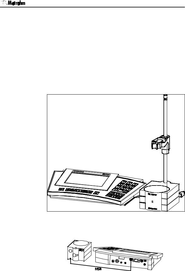
Fig. 1: 781 pH/Ion Meter connected to 801Magnetic Stirrer
1.1Instrument description
Both instrument versions, the 781 pH/Ion Meter and the 780 pH Meter, are used for measuring pH, temperature and potential reliably and at high resolution. The 781 pH/Ion Meter differs from the 780 pH Meter by having an additional operating mode for the potentiometric determination of the concentration by using ion-selective electrodes (Conc mode).
Both instruments have comprehensive monitoring functions (for calibration, validation and service intervals), diagnostic functions and an au-
780/781 pH/Ion Meter, Manual |
1 |

1.1 Instrument description
tomatic pH electrode test. Up to 100 values can be stored in the memory together with the most important additional data; these can be viewed and outputted as a report. All the parameter settings for a measuring mode can be permanently stored as a method.
All stored information (measured values, configuration, parameters, etc.) can be transmitted via the RS 232 interface to a printer or computer for output as a report.
Both instruments have the following features:
•Dot-matrix display for both the continuous display of the measured value and for showing the user dialog.
•High-impedance measuring input for pH, redox or ISE sensors, a connection for a separate reference electrode and an input for temperature sensors (Pt1000 or NTC).
•MSB connection (Metrohm Serial Bus) for a stirrer and for a Dosimat Plus.
•RS 232 connection for a serial printer or a computer.
•A connection for an external keyboard or a barcode reader.
The 781 pH/Ion Meter has an additional Conc mode which allows the measurement of the concentration by using ion-selective electrodes, either directly after calibration or by standard or sample addition methods. Such a calibration or standard addition can be carried out either manually or automatically. In the latter method a standard solution is added automatically by a Dosimat Plus included in the system. The calibration concentrations or the standard additions are calculated automatically according to the given conditions and these are added with great accuracy.
2 |
780/781 pH/Ion Meter, Manual |

1 Introduction
1.2Parts and controls
Fig. 2: Front view of the 780 pH Meter or 781 pH/Ion Meter
1 LCD display |
3 Main function keys |
2On/Off key
Key for switching the instrument on and off
4Input, navigation and function keys
Each key has several functions;
the particular function depends on the work status of the instrument
780/781 pH/Ion Meter, Manual |
3 |
1.2 Parts and controls
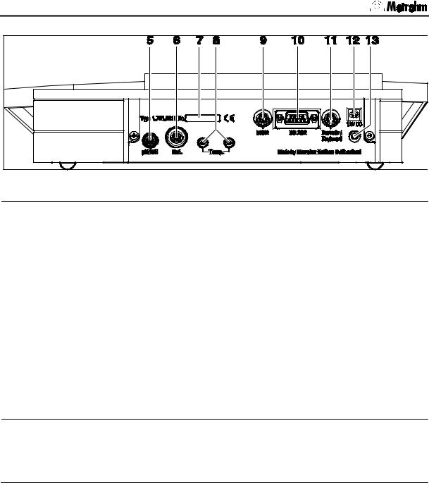
Fig. 3: Rear view of the 780 pH Meter or 781 pH/Ion Meter
5 |
Connection for potentiometric electrodes |
10 |
RS232 interface |
|
pH, ISE, redox or silver electrodes |
|
Connection for printer or PC |
|
with built-in or separate reference elec- |
|
|
|
trode; socket type F |
|
|
|
|
|
|
6 |
Connection for separate reference |
11 |
Barcode reader/ |
|
electrode |
|
Keyboard connection |
|
4 mm socket type B |
|
|
|
|
|
|
7 |
Serial number |
12 |
12V power connection |
|
|
|
|
8 |
Connection for temperature sensor |
13 |
Grounding connection |
|
Pt1000 or NTC, for connection with two 2 |
|
For measurements in grounded solu- |
|
mm B-plugs; 6.2103.130 and 6.2103.140 |
|
tions, grounding of the instrument |
|
Adapters are included for use with 4 mm |
|
may be advantageous to avoid inter- |
|
banana plugs |
|
ferences; 4 mm socket type B |
9MSB connection
(Metrohm Serial Bus) for connecting a stirrer and/or Dosimat Plus, directly or via the optional Remote Box (6.2148.010)
4 |
780/781 pH/Ion Meter, Manual |
1 Introduction
1.3Information about this Manual
Please study this Manual carefully before you start to use the instrument. The Manual contains information and warnings that must be observed by the user in order to guarantee the safe use of the instrument.
1.3.1Notation and pictograms
The following notations and pictograms (symbols) are used in this
Manual:
Range |
Menu item, parameter or input value |
<MODE> Key
12Operating element
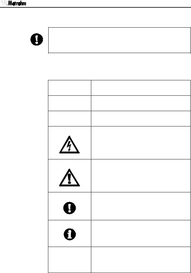
Danger
This symbol indicates a possible risk of death or injury if the given information is not properly observed.
Warning
This symbol indicates a possible risk of damage to the instrument or its components if the given information is not properly observed.
Attention
This symbol indicates important information.
Please read it carefully before you continue.
Information
This symbol indicates additional information and tips.
TIP
TIP ! This symbol indicates information that may be of particular use to you.
780/781 pH/Ion Meter, Manual |
5 |
1.4 Safety information
1.4Safety information
Warning!
This instrument should only be used in accordance with the information given in this Manual.
1.4.1Electrical safety
Please observe the following guidelines:
•Only qualified Metrohm technicians should carry out service work on electronic components.
•Do not open the pH/Ion Meter housing. This could destroy the pH/Ion Meter. Inside the housing there are no components that the user can service or exchange.
Electrical safety when handling the 780 pH Meter and the 781 pH/Ion
Meter is guaranteed within the framework of the IEC 61010 Standard.
The following points must be observed:
Please make sure that the external power supply is always kept dry.
Protect it against direct liquid contact .
Electronic components are sensitive to electrostatic charges and can be destroyed by a discharge. Always switch off the pH/Ion Meter before making or breaking electrical connections on the rear panel of the instrument.
1.4.2General handling rules
Handling solutions
When working with water or other solutions in the immediate vicinity of the pH/Ion Meter please avoid excessive liquid splashes on the instrument housing or power supply. Any such splashes must be removed as quickly as possible in order to prevent the liquid from entering the instrument or the power supply.
6 |
780/781 pH/Ion Meter, Manual |

2 Installation
2 Installation
2.1Instrument setup
2.1.1Packaging
The 780/781 pH/Ion Meter and its specially packed accessories are supplied in very protective special packaging made of shock absorbing polypropylene foam. Please store this packaging in a safe place; it is the only way in which the safe transport of the instrument can be guaranteed. Should you wish to dispose of it please consider suitable disposal or recycling processes.
2.1.2Checks
Please check that the delivery is complete and undamaged immediately on receipt (compare with delivery note and list of accessories given in
Section 9.6).
2.1.3Location
Place the instrument on a suitable vibration-free laboratory bench, protected from corrosive atmospheres and contact with chemicals.
780/781 pH/Ion Meter, Manual |
7 |
2.2 Connecting the accessories
2.2Connecting the accessories
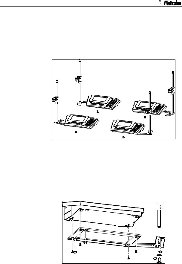
Both the stand for attaching the stirrer, clamping ring and electrode holder as well as the pH/Ion Meter itself can be mounted on the supplied stand base.
You can chose between the arrangements shown in Fig. 4 to suit your own particular working preference.
Fig. 4: Possible arrangements for mounting the base plate
Versions A and B are intended for mounting an 801 Magnetic stirrer on the leftand right-hand side of the pH/Ion Meter respectively. If you frequently work without such a permanently attached stirrer then you can mount the base plate so that you have space for the sample vessel directly in front of the support rod (versions C and D).
Attach the base plate with the screws provided as shown in Fig. 5. The rubber feet included prevent the system from slipping about on the work bench and should therefore be stuck on to the base plate.
Fig. 5: Attaching the support rod and base plate
8 |
780/781 pH/Ion Meter, Manual |
2 Installation
2.3Connecting optional devices
Devices which are to be remotely controlled from the pH/Ion Meter (e.g. Metrohm stirrers or Dosimat Plus devices) are connected to MSB connection 9. This can be carried out either directly (801 Magnetic Stirrer or 802 Rod Stirrer with 804 Ti-Stand) or via the optionally available 6.2148.010 Remote Box (e.g. Dosimat Plus).
2.3.1Connecting the 801 Magnetic Stirrer
Mount the magnetic stirrer on the support rod before attaching the clamping ring (6.2013.010) and the electrode holder (6.2021.020). Further details are given in the corresponding Manual.
For example, the ready-mounted system could look like this:
Fig. 6: Ready-mounted pH/ISE measuring system
The 801 Magnetic Stirrer is controlled via MSB connection 9. The stirrer is connected to it directly:
Fig. 7: 780 pH Meter / 781 pH/Ion Meter – 801 Magnetic stirrer
780/781 pH/Ion Meter, Manual |
9 |
2.3 Connecting optional devices
2.3.2Connecting the 802 Rod Stirrer
The 802 Rod Stirrer, in combination with the 804 Ti Stand, can also be connected directly to the pH/Ion Meter. This is done by plugging the MSB connection cable of the 804 Ti Stand into MSB connection 9 of the pH/Ion Meter:
Fig. 8: 780 pH Meter / 781 pH/Ion Meter – 802 Rod stirrer
10 |
780/781 pH/Ion Meter, Manual |
2 Installation
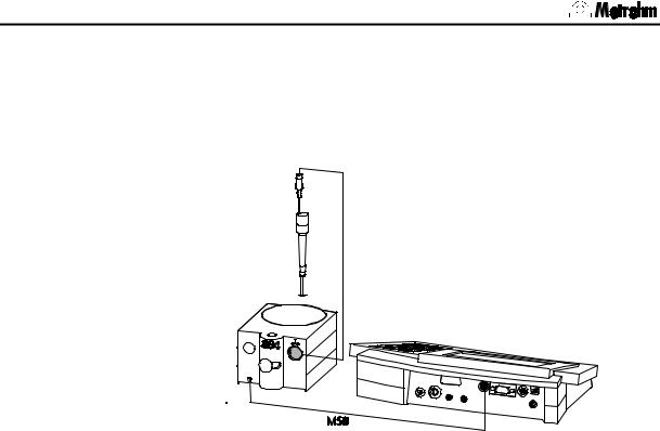
2.3.3Connecting a Dosimat Plus (only 781)
Controlled addition of standard or sample solutions
For automatic calibration as well as for the addition of standard or samples in the Conc mode with the 781 pH/Ion Meter the Metrohm 865 and 876 Dosimat Plus devices can be connected via the separately available 6.2148.010 Remote Box. Control is carried out via the 6.2141.350 cable:
Fig. 9: 781 pH/Ion Meter – Dosimat Plus
If a Dosimat Plus is used then a stirrer is normally also required. This is then connected directly with the MSB connection of the 6.2148.010 Remote Box (stirrer: 801 or 802+804).
Please note that for the standard addition the mode “DOS” is set on the Dosimat Plus. The activation pulse must be activated on the pH Meter as well as the Dosimat Plus. Furthermore, the Dosimat Plus must be in the status “HOLD”. You can set the status to “HOLD” by pressing the “Go” key once (check: the display of the Dosimat Plus shows “HOLD” in the top right-hand corner).
780/781 pH/Ion Meter, Manual |
11 |
2.3 Connecting optional devices
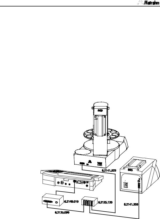
2.3.4Connecting a sample changer
For simple automated measurement of several samples and standards with the pH/Ion Meter the Metrohm Compact Sample Changer 869 can be connected. Communication takes place via the 6.2148.010 Remote Box, i.e. the measurements are triggered by the sample changer and their completion is also transmitted by the pH/Ion Meter via the remote connection. The individual steps for processing a series of samples or standards are defined as a method in the sample changer.
Please note that when work is carried out in this way that no sample data is transferred between the sample changer and the pH/Ion Meter. This means that the assignment of the report outputs is only possible by using the consecutive run number (see Section 5.4).
The connection of a Compact Sample Changer 869 and a Dosimat Plus 865 for automatic calibration with standard addition is described here as an example. A detailed description of how to program a method in the Compact Sample Changer 869 is given in the corresponding Manual of the instrument.
Fig. 10: 781 pH/Ion Meter – Dosimat Plus – Sample changer
12 |
780/781 pH/Ion Meter, Manual |
2 Installation
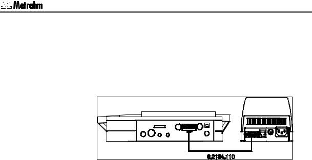
2.3.5Connecting a printer
A printer with a serial or parallel interface can be connected to the RS232 interface for printing out reports.
The connection of the 40-character Custom DP40-S4N printer (Metrohm ordering number: 2.140.0200) with the serial 6.2134.110 Cable is described as an example:
Fig. 11: 780 pH Meter / 781 pH/Ion Meter – Printer |
The transmission parameters for the pH/Ion Meter and the printer must be the same. On the pH/Ion Meter these are set under
CONFIG/peripheral units/character set: (see Section 5.6)
and under
CONFIG/RS232 settings (see Section 5.7).
These settings and other possible printer connections are given in the following table. If you wish to connect a printer which is not mentioned here then make sure that it emulates the Epson mode or uses the international character set according to IBM Standard Table 437 and IBMcompatible graphics control characters.
Please observe the paper feed settings after each report printout (see
Section 5.1).
The settings for graph sizes in the printer output are accessible in the setup of the pH/Ion Meter and are described in Section 7.5.3. This can particularly be necessary for single sheet printers (i.e. HP Desk Jet).
780/781 pH/Ion Meter, Manual |
13 |
2.3 Connecting optional devices
Printer |
Cable |
780/781 settings |
|
|
|
|
|
|
|
|
|
|
|
Printer settings |
|
|
|
|
|
|
|
|
|
|
|
|
|
|
|||||||||||||||||||||||
|
|
|
|
|
|
|
|
|
|
|
|
|
|
|
|
|
|
|
|
|
|
|
|
|
|
|
|
|
|
|
|
|
|
|
|
|
|
|
|
|
|
|
|
|
|
|
|
||||
Custom |
6.2134.110 |
Character Set: |
Citizen |
IDP-560 EMULATION |
|
|
|
|
|
|
|
|
|
|
|
|
|
|
|
|
|
|
|
||||||||||||||||||||||||||||
DP40-S4N |
|
Baud Rate: |
9600 |
FONT MAP = ENGLAND * |
|
|
|
|
|
|
|
|
|
|
|
|
|
|
|||||||||||||||||||||||||||||||||
|
|
Data Bit: |
8 |
PRINT = REVERSE |
|
|
|
|
|
|
|
|
|
|
|
|
|
|
|
|
|
|
|
|
|
|
|
||||||||||||||||||||||||
|
|
LITTLE |
|
|
|
|
|
|
|
|
|
|
|
|
|
|
|
|
|
|
|
|
|
|
|
|
|
|
|
|
|
|
|
|
|
|
|
|
|
|
|||||||||||
|
|
Stop Bit: |
1 |
|
|
|
|
|
|
|
|
|
|
|
|
|
|
|
|
|
|
|
|
|
|
|
|
|
|
|
|
|
|
|
|
|
|
|
|
|
|
||||||||||
|
|
CR CODE = VOID |
|
|
|
|
|
|
|
|
|
|
|
|
|
|
|
|
|
|
|
|
|
|
|
|
|
|
|
||||||||||||||||||||||
|
|
Parity: |
none |
|
|
|
|
|
|
|
|
|
|
|
|
|
|
|
|
|
|
|
|
|
|
|
|
|
|
|
|||||||||||||||||||||
|
|
CR AFTER B. FULL = VOID |
|
|
|
|
|
|
|
|
|
|
|
||||||||||||||||||||||||||||||||||||||
|
|
Handshake: |
HWs |
CR ON B. EMPTY = VALID |
|
|
|
|
|
|
|
|
|
|
|
||||||||||||||||||||||||||||||||||||
|
|
|
|
BUFFER 1K BYTE |
|
|
|
|
|
|
|
|
|
|
|
|
|
|
|
|
|
|
|
|
|
|
|
|
|
|
|
||||||||||||||||||||
|
|
|
|
BAUD RATE = 9600 |
|
|
|
|
|
|
|
|
|
|
|
|
|
|
|
|
|
|
|
|
|
|
|
||||||||||||||||||||||||
|
|
|
|
PROTOCOL = 8,N,1 |
|
|
|
|
|
|
|
|
|
|
|
|
|
|
|
|
|
|
|
|
|
|
|
||||||||||||||||||||||||
|
|
|
|
FLOW CONTROL CTS-RTS |
|
|
|
|
|
|
|
|
|
|
|
|
|
|
|||||||||||||||||||||||||||||||||
|
|
|
|
(*) FRANCE also for Italian, Spanish |
|||||||||||||||||||||||||||||||||||||||||||||||
|
|
|
|
and Portuguese, |
|
|
|
|
|
|
|
|
|
|
|
|
|
|
|
|
|
|
|
|
|
|
|
|
|
|
|
||||||||||||||||||||
|
|
|
|
GERMANY also for Swedish. |
|
|
|
|
|
|
|
|
|
|
|
||||||||||||||||||||||||||||||||||||
Seiko |
6.2134.110 |
Character Set: |
Seiko |
none |
|
|
|
|
|
|
|
|
|
|
|
|
|
|
|
|
|
|
|
|
|
|
|
|
|
|
|
|
|
|
|
|
|
|
|
|
|
|
|||||||||
DPU-414 |
|
Baud Rate: |
9600 |
|
|
|
|
|
|
|
|
|
|
|
|
|
|
|
|
|
|
|
|
|
|
|
|
|
|
|
|
|
|
|
|
|
|
|
|
|
|
|
|
|
|
|
|
|
|
|
|
|
|
Data Bit: |
8 |
|
|
|
|
|
|
|
|
|
|
|
|
|
|
|
|
|
|
|
|
|
|
|
|
|
|
|
|
|
|
|
|
|
|
|
|
|
|
|
|
|
|
|
|
|
|
|
|
|
|
Stop Bit: |
1 |
|
|
|
|
|
|
|
|
|
|
|
|
|
|
|
|
|
|
|
|
|
|
|
|
|
|
|
|
|
|
|
|
|
|
|
|
|
|
|
|
|
|
|
|
|
|
|
|
|
|
Parity: |
none |
|
|
|
|
|
|
|
|
|
|
|
|
|
|
|
|
|
|
|
|
|
|
|
|
|
|
|
|
|
|
|
|
|
|
|
|
|
|
|
|
|
|
|
|
|
|
|
|
|
|
Handshake: |
HWs |
|
|
|
|
|
|
|
|
|
|
|
|
|
|
|
|
|
|
|
|
|
|
|
|
|
|
|
|
|
|
|
|
|
|
|
|
|
|
|
|
|
|
|
|
|
|
|
|
Citizen |
6.2134.050 |
Character Set: |
Citizen |
|
|
|
|
ON |
|
|
|
|
|
|
|
|
|
|
|
|
|
|
|
|
|
|
|
|
|
|
|
|
|
|
|
|
|
|
|
|
|
|
|
|
|
|
|||||
iDP562 RS |
|
Baud Rate: |
9600 |
|
|
|
|
|
|
|
|
|
|
|
|
|
|
|
|
|
|
|
|
|
|
|
|
|
|
|
|
|
|
|
|
|
|
|
|
|
|
|
|
|
|
|
|
|
|
|
|
|
|
Data Bit: |
8 |
|
|
|
|
|
|
|
|
|
|
|
|
|
|
|
|
|
|
|
|
|
|
|
|
|
|
|
|
|
|
|
|
|
|
|
|
|
|
|
|
|
|
|
|
|
|
|
|
|
|
|
|
|
|
|
|
|
|
|
|
|
|
|
|
|
|
|
|
|
|
|
|
|
|
|
|
|
|
|
|
|
|
|
|
|
|
|
|
|
|
|
|
|
|
|
|
|
|
||
|
|
Stop Bit: |
1 |
|
|
|
|
|
|
|
|
|
1 2 |
|
|
3 |
4 |
5 |
|
|
6 |
7 |
|
8 |
|
|
9 |
10 |
|
|
|||||||||||||||||||||
|
|
|
|
|
|
|
|
|
|
|
|
|
|
|
|
|
|
|
|||||||||||||||||||||||||||||||||
|
|
Parity: |
none |
|
|
|
|
|
|
|
|
|
|
|
|
|
|
|
|
|
|
|
|
|
|
|
|
|
|
|
|
|
|
|
|
|
|
|
|
|
|
|
|
|
|
|
|
|
|
|
|
|
|
|
|
SSW1 |
|
|
|
|
|
|
|
|
|
|
|
|
|
|
|
|
|
|
|
|
|
|
|
|
|
|
|
|
|
|
|
|
|
|
|
|
|
|
|
||||||||
|
|
Handshake: |
HWs |
|
|
|
|
|
|
|
|
|
|
|
|
|
|
|
|
|
|
|
|
|
|
|
|
|
|
|
|
|
|
|
|
|
|
|
|
|
|
|
|
|
|
|
|
|
|
|
|
Epson LX- |
6.2134.050 |
As above, but |
|
see Printer Manual |
|
|
|
|
|
|
|
|
|
|
|
|
|
|
|
|
|
|
|
|
|
|
|
||||||||||||||||||||||||
300+ |
|
Character Set: |
Epson |
|
|
|
|
|
|
|
|
|
|
|
|
|
|
|
|
|
|
|
|
|
|
|
|
|
|
|
|
|
|
|
|
|
|
|
|
|
|
|
|
|
|
|
|
|
|
|
|
HP Desk Jet |
6.2134.050 |
Character Set: |
HP |
|
|
|
|
|
|
|
|
|
|
|
|
|
|
|
|
|
|
|
|
|
|
|
|
|
|
|
|
|
|
|
|
|
|
|
|
|
|
|
|
|
|
|
|
|
|
|
|
|
|
|
|
|
|
|
|
|
|
|
|
|
|
|
|
|
|
|
|
|
|
|
|
|
|
|
|
|
|
|
|
|
|
|
|
|
|
|
|
|
|
|
|
|
|
|
|
||||
|
|
|
|
|
|
|
|
|
|
|
|
|
|
|
|
|
|
|
|
|
|
|
|
|
|
|
|
|
|
|
|
|
|
|
|
|
|
|
|
|
|
|
|
|
|
|
|
||||
with serial |
|
Baud Rate: |
9600 |
|
A: |
|
|
|
|
|
|
|
|
|
|
|
|
|
|
|
|
|
|
|
|
|
|
|
|
|
|
|
|
|
|
|
|
|
|
|
|
|
|
|
|||||||
|
|
|
|
1 |
|
|
|
2 |
|
|
3 |
|
|
4 |
|
|
|
5 |
|
|
|
6 |
|
|
7 |
|
|
|
8 |
|
|
|
|
|
|||||||||||||||||
interface |
|
Data Bit: |
8 |
|
|
|
|
|
|
|
|
|
|
|
|
|
|
|
|
|
|
|
|
|
|
|
|
|
|
|
|
|
|
|
|
|
|
|
|||||||||||||
|
|
|
|
|
A4 Paper |
|
|
|
|
|
|
|
|
|
|
|
|
|
|
|
|
|
|
|
|
|
|
|
|
|
|||||||||||||||||||||
|
|
|
|
|
|
|
|
|
|
|
|
|
|
|
|
|
|
|
|
|
|
|
|
|
|||||||||||||||||||||||||||
|
|
|
|
|
|
|
|
|
|
|
|
|
|
|
|
|
|
|
|
|
|
|
|
|
|
|
|
|
|
|
|
|
|
|
|
|
|
|
|
|
|
|
|||||||||
|
|
Stop Bit: |
1 |
B: |
|
|
|
|
|
|
|
|
|
|
|
|
|
|
|
|
|
|
|
|
|
|
|
|
|
|
|
|
|
|
|
|
|
|
|
|
|
|
|||||||||
|
|
|
|
|
|
|
|
|
|
|
|
|
|
|
|
|
|
|
|
|
|
|
|
|
|
|
|
|
|
|
|
|
|
|
|
|
|
|
|
||||||||||||
|
|
|
|
|
|
|
|
|
|
|
|
|
|
|
|
|
|
|
|
|
|
|
|
|
|
|
|
|
|
|
|
|
|
|
|
|
|
|
|
||||||||||||
|
|
Parity: |
none |
|
|
|
|
|
|
|
|
|
|
|
|
|
|
|
|
|
|
|
|
|
|
|
|
|
|
|
|
|
|
|
|
|
|
|
|
|
|
||||||||||
|
|
|
|
|
|
|
|
|
|
2 |
|
|
|
|
|
|
|
|
|
|
|
|
|
|
|
|
|
|
|
|
|
|
|
|
|
|
|
|
|||||||||||||
|
|
|
|
|
1 |
|
|
|
|
|
3 |
|
|
4 |
|
5 |
|
|
6 |
|
|
7 |
|
|
8 |
|
|
|
|
||||||||||||||||||||||
|
|
Handshake: |
HWs |
|
|
|
|
|
|
|
|
|
|
|
|
|
|
|
|
|
|
|
|
|
|
|
|
|
|
|
|
|
|
||||||||||||||||||
|
|
|
|
|
|
|
|
|
|
|
|
|
|
|
|
|
|
|
|
|
|
|
|
||||||||||||||||||||||||||||
|
|
|
|
|
|
|
|
|
|
|
|
|
|
|
|
|
|
|
|
|
|
|
|
|
|
|
|
|
|
|
|
|
|
|
|||||||||||||||||
|
|
|
|
|
|
|
|
|
|
|
|
|
|
|
|
|
|
|
|
|
|
|
|
|
|
|
|
|
|
|
|
|
|
|
|
|
|
|
|
|
|
|
|
|
|
|
|
|
|
||
HP Desk Jet |
2.145.0330 |
Character Set: |
HP |
see Printer Manual |
|
|
|
|
|
|
|
|
|
|
|
|
|
|
|
|
|
|
|
|
|
|
|
||||||||||||||||||||||||
with parallel |
RS232/ |
Baud Rate: |
9600 |
|
|
|
|
|
|
|
|
|
|
|
|
|
|
|
|
|
|
|
|
|
|
|
|
|
|
|
|
|
|
|
|
|
|
|
|
|
|
|
|
|
|
|
|
|
|
|
|
interface |
Parallel |
Data Bit: |
8 |
|
|
|
|
|
|
|
|
|
|
|
|
|
|
|
|
|
|
|
|
|
|
|
|
|
|
|
|
|
|
|
|
|
|
|
|
|
|
|
|
|
|
|
|
|
|
|
|
|
Converter |
Stop Bit: |
1 |
|
|
|
|
|
|
|
|
|
|
|
|
|
|
|
|
|
|
|
|
|
|
|
|
|
|
|
|
|
|
|
|
|
|
|
|
|
|
|
|
|
|
|
|
|
|
|
|
|
|
Parity: |
none |
|
|
|
|
|
|
|
|
|
|
|
|
|
|
|
|
|
|
|
|
|
|
|
|
|
|
|
|
|
|
|
|
|
|
|
|
|
|
|
|
|
|
|
|
|
|
|
|
|
|
Handshake: |
HWs |
|
|
|
|
|
|
|
|
|
|
|
|
|
|
|
|
|
|
|
|
|
|
|
|
|
|
|
|
|
|
|
|
|
|
|
|
|
|
|
|
|
|
|
|
|
|
|
|
|
|
|
|
|
|
|
|
|
|
|
|
|
|
|
|
|
|
|
|
|
|
|
|
|
|
|
|
|
|
|
|
|
|
|
|
|
|
|
|
|
|
|
|
|
|
|
|
|
|
|
|
14 |
780/781 pH/Ion Meter, Manual |
2 Installation
2.3.6Connecting a computer
The report output via the RS232 interface can be made to either a printer or a PC. With the program Metrodata Vesuv 3.0 for Windows it is possible to implement automatic data acquisition and evaluation.
This is done by connecting RS232 interface 10 of the pH/Ion Meter using the optionally available 6.2134.040 Cable (9-pin/9-pin) with a free serial COM port on the PC. If only a 25-pin COM port is available then the optionally available 6.2125.110 Cable (9-pin/25-pin) or a commercially available adapter must be used.
Settings
The RS232 interface must be configured with identical settings on both the connected instruments (PC and pH/Ion Meter). You should select the standard values for the pH/Ion Meter configuration under CONFIG/RS232 settings (see Section 5.7):
Baud Rate: 9600
Data Bit: 8
Stop Bit: 1
Parity: none
Handshake: HWs
Please note that, before starting the program 'Vesuv Datalogger', the pH/Ion Meter must have been configured correctly, connected up and switched on. When the Vesuv program is started it automatically checks the configuration of the connected instrument and makes the corresponding settings for the report output so that data acquisition functions properly.
As well as the data acquisition function described above, the 780/781 pH/Ion Meter also has numerous remote control possibilities that allow the complete control of the instrument via the RS232 interface. However, as the utilization of this option only makes sense in very special situations, you can obtain detailed information about the remote control language of the pH/Ion Meter from your local Metrohm agency in a separate document (780/781 pH/Ion Meter Operation via RS232; 8.781.1113).
780/781 pH/Ion Meter, Manual |
15 |
2.4 Connecting the electrodes and sensors
2.4Connecting the electrodes and sensors
On its rear panel the 780/781 pH/Ion Meter has connections for a potentiometric electrode 5, a separate reference electrode 6 and a temperature sensor 8.
Connect your electrodes and sensors according to the following diagram to the switched off pH/Ion Meter:
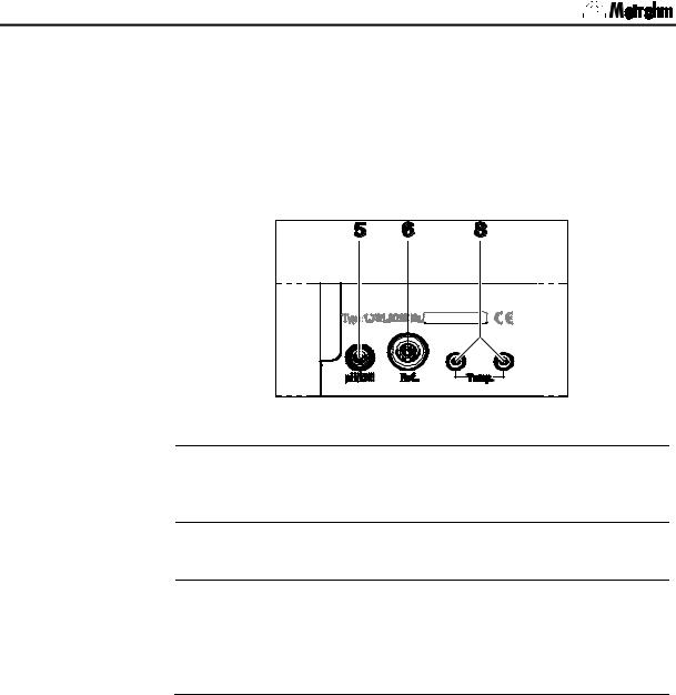
Fig. 12: Connecting sensors
5Connection for potentiometric electrodes
pH, ISE, redox or silver electrodes with built-in or separate reference electrode; plug F
6Connection for separate reference electrode plug B, 4 mm
8Connection for temperature sensor
Pt1000 or NTC, connected via two 2 mm banana plugs, reducing adapters for 4 mm plug B may be necessary (6.2103.130 / 6.2103.140). Please observe color classification for shielding purposes.
To help you choose the optimal potentiometric electrode for your particular application Metrohm can provide you with a range of information material:
Catalog: |
Metrosensor Electrodes |
Product booklet: |
Electrodes for pH Measurement |
Monograph 8.015.5003: |
Electrodes in Potentiometry |
You can obtain these documents from your local Metrohm agency or under www.metrohm.com.
16 |
780/781 pH/Ion Meter, Manual |
2 Installation
2.5Mains connection
The pH/Ion Meter has an external power supply (6.2153.000) providing 12V (DC). This is connected to 12V mains connection 12.
Mains cable
One of the following cables is supplied with the instrument
•6.2154.000 Mains cable 2 Pol (C7) – EU (XVI)
•6.2154.010 Mains cable 2 Pol (C7) – US (N1/15)
•6.2154.020 Mains cable 2 Pol (C7) – GB (BS89/3)
•6.2154.030 Mains cable 2 Pol (C7) – AUS (SAA/2)
and is connected to the external power supply.
Please make sure that the power supply is always kept dry. Protect it against direct liquid contact .
2.6Switch on
After the selected accessories have been connected switch on the
pH/Ion Meter with the <ON/OFF> key (see also Section 4.3). The in- ON/OFF strument will start in the last operating mode to have been used for
measuring pH, temperature, potential or concentration (781 only).
During the switch-on process an instrument checking routine is carried out automatically. If an error message is displayed here ('Err x') then please contact your local Metrohm agency.
780/781 pH/Ion Meter, Manual |
17 |
2.7 Initial configuration
2.7Initial configuration
The pH/Ion Meter is delivered with standard settings for the configuration and method parameters. Many of these can be reset at any time by pressing the <CLEAR> key during input (see also Section 4.3). If it should ever be necessary to reset the configuration of the instrument to its original condition then this can be carried out by a re-initialization of the instrument memory (see Section 8.5).
Before you start to make measurements please check the following configuration settings and, if necessary, alter them according to your own requirements. If you first want to make yourself familiar with the operation of the pH/Ion Meter and the various editing possibilities then please read Sections 4.1, 4.2 and 4.4. More detailed explanations of the individual configuration settings are given in Section 5.
Dialog language: english
CONFIG/Verschiedenes/Dialog:english
After this choice has been confirmed with <ENTER> the dialog language changes immediately. For example, this item would then appear.
CONFIG/auxiliaries/dialog:english
Please switch the instrument off and on if this setting has been changed.
Date and time
CONFIG/auxiliaries/date and /time
Please check that the date and time are correct.
Temperature sensor and unit
CONFIG/auxiliaries/Temp.sensor and /Temp.unit
Enter the type of temperature sensor that is connected. If no temperature sensor is connected and you always want to enter the measuring temperature manually then you can ignore this setting.
18 |
780/781 pH/Ion Meter, Manual |

3 Short operating tutorial
3 Short operating tutorial
In this section the necessary steps for carrying out a simple pH and ion measurement with calibration are described. The instructions are limited to those steps that are absolutely necessary and will enable you to carry out your first measurements with the pH/Ion Meter directly. The operating principles are described in Section 4.4.
3.1pH measurement
3.1.1Requirements
The following instruments, accessories and solutions are required for carrying out the pH calibration and measurement described below:
•780 pH Meter (2.780.0010) or 781 pH/Ion Meter (2.781.0010)
•801 Magnetic Stirrer (2.801.0010)
Other stirrers can also be used (see Section 5.6).
•pH electrode (enclosed)
Or another pH electrode with Pt1000 temperature sensor, e.g.: 6.0258.600 Unitrode, LL pH glass, with cable 6.2104.600, 2 mm temp. plug
6.0257.000 Aquatrode Plus for ion-deficient water, 4 mm temp. plug 6.0228.000 Solitrode, LL pH glass, PP shaft, 4 mm temp. plug
•Calibration buffers
Metrohm buffer solutions pH 4.00, 7.00 and 9.00 (6.2307.230)
3.1.2Preparations
Before you start this short tutorial you must ensure that the instrument and accessories have been correctly installed as described in Section 2. The most important points concerning the installation are briefly given again below (please refer to the Section mentioned for details). If you are not certain whether all the settings (CONFIG and PARAMETER pH) correspond to the original conditions you can first reset any alterations by initializing the memory (RAM Initialization) (see Section 8.5).
The calibration parameters for the pH mode are set for a calibration using two Metrohm buffers as default (see Section 6.2.2). If you want to use other buffers then the corresponding buffer type must be entered.
1 |
pH/Ion Meter installation |
|
|
|
• |
Set up instrument |
Section 2.1 |
|
• |
Connect stirrer |
Section 2.3.1 |
|
• |
Connect electrode |
Section 2.4 |
|
• |
Mains connection |
Section 2.5 |
780/781 pH/Ion Meter, Manual |
19 |
3.1 pH measurement
ON/OFF |
2 |
Initial configuration |
|
|
|
• |
Switch on pH/Ion Meter |
Section 5.4 |
|
|
|
|||
|
|
• |
Set dialog language |
Section 5.4 |
CONFIG |
|
• |
Set date/time |
Section 5.4 |
|
• |
Set temperature sensor |
Section 5.4 |
|
|
|
|||
3.1.3pH calibration
CAL
ENTER
1Start calibration with first buffer
•Immerse pH electrode in buffer solution pH 7
•Switch on stirrer with <STIRRER>
•Start calibration with <CAL>
•If no temperature sensor is connected:
enter the temperature and exit with <ENTER>
2Continue calibration with second buffer
•Remove pH electrode from first buffer, rinse with water and blot off gently with a lint-free tissue
•Immerse pH electrode in second buffer solution pH 4 and continue calibration sequence with <ENTER>
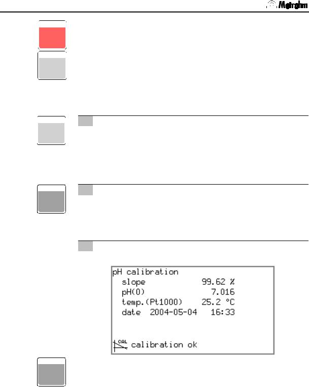
3Result
•Wait for potential measurement, result will be displayed:
• After 30 s the pH/Ion Meter will switch back automatically to
ENTER the measurement display. This can also be done immediately with <ENTER>.
20 |
780/781 pH/Ion Meter, Manual |
Loading...