


 Loading...
851 Titrando
Manual
8.851.8004EN

Metrohm AG CH-9100 Herisau Switzerland
Phone +41 71 353 85 85 Fax +41 71 353 89 01 info@metrohm.com www.metrohm.com
851 Titrando
Manual
8.851.8004EN |
04.2013 ek/jb |
Teachware Metrohm AG CH-9100 Herisau
teachware@metrohm.com
This documentation is protected by copyright. All rights reserved.
Although all the information given in this documentation has been checked with great care, errors cannot be entirely excluded. Should you notice any mistakes please send us your comments using the address given above.
Documentation in additional languages can be found on
http://documents.metrohm.com.
|
Table of contents |
Table of contents
1 Introduction |
1 |
||
1.1 |
|
The Titrando system ............................................................. |
1 |
1.2 |
|
Instrument description ......................................................... |
2 |
1.3 |
Titration modes – Measuring modes – Dosing com- |
|
|
|
|
mands .................................................................................... |
2 |
1.4 |
|
About the documentation ................................................... |
3 |
1.4.1 |
Symbols and conventions ........................................................ |
3 |
|
1.5 |
|
Safety instructions ................................................................ |
4 |
1.5.1 |
General notes on safety ........................................................... |
4 |
|
1.5.2 |
Electrical safety ........................................................................ |
4 |
|
1.5.3 |
Working with liquids ................................................................ |
5 |
|
1.5.4 |
Flammable solvents and chemicals ........................................... |
6 |
|
1.5.5 |
Recycling and disposal ............................................................. |
6 |
|
2 Overview of the instrument |
7 |
|
3 Installation |
|
9 |
3.1 |
Setting up the instrument .................................................... |
9 |
3.1.1 |
Packaging ................................................................................ |
9 |
3.1.2 |
Checks .................................................................................... |
9 |
3.1.3 |
Location .................................................................................. |
9 |
3.2 |
Connecting a controller ........................................................ |
9 |
3.2.1 |
Operation ................................................................................ |
9 |
3.3 |
Connecting MSB devices .................................................... |
13 |
3.3.1 |
Connecting a dosing device ................................................... |
14 |
3.3.2 |
Connecting a stirrer or titration stand .................................... |
15 |
3.3.3 |
Connecting a Remote Box ..................................................... |
16 |
3.4 |
Connecting USB devices ..................................................... |
17 |
3.4.1 |
General ................................................................................. |
17 |
3.4.2 |
Connecting a USB hub ........................................................... |
18 |
3.4.3 |
Connecting a printer .............................................................. |
18 |
3.4.4 |
Connecting a balance ............................................................ |
19 |
3.4.5 |
Connecting a PC keyboard (only for operation with Touch |
|
|
Control) ................................................................................. |
20 |
3.4.6 |
Connecting a barcode reader ................................................. |
21 |
3.5 |
Titration vessel for coulometric KF titration .................... |
23 |
3.5.1 |
Mounting the coulometer cell ................................................ |
23 |
3.5.2 |
Coulometer cell – Standard setup .......................................... |
24 |
3.5.3 |
Coulometer cell with addition and aspiration tube (utilization |
|
|
with Ti Stand) ........................................................................ |
29 |
851 Titrando |
III |
Table of contents |
|
|
|
|
3.5.4 Coulometer cell with aspiration equipment (utilization with |
|
|
|
|
Dosino) .................................................................................. |
30 |
|
3.5.5 Coulometer cell with Karl Fischer oven ................................... |
31 |
|
|
3.5.6 Coulometer cell with sample changer .................................... |
31 |
|
|
3.6 |
Connecting sensors ............................................................ |
32 |
|
3.6.1 Connecting a generator electrode .......................................... |
32 |
|
|
3.6.2 Connecting an indicator electrode ......................................... |
32 |
|
|
3.6.3 Connecting a temperature sensor .......................................... |
33 |
|
4 |
Coulometric titration |
35 |
|
|
4.1 |
Principle of coulometry according to Karl Fischer .......... |
35 |
|
4.2 |
Working with water standards ......................................... |
36 |
|
4.2.1 |
Certified water standards ....................................................... |
36 |
|
4.2.2 |
Practical recommendations .................................................... |
36 |
|
4.3 |
Sample addition .................................................................. |
38 |
|
4.3.1 Size of the sample size ........................................................... |
38 |
|
|
4.3.2 Working with liquid samples .................................................. |
38 |
|
|
4.3.3 Working with solid samples ................................................... |
39 |
|
|
4.4 |
Optimum working conditions ........................................... |
40 |
|
4.4.1 |
General ................................................................................. |
40 |
|
4.4.2 |
Drift ...................................................................................... |
40 |
|
4.4.3 |
Reagent replacement ............................................................. |
41 |
|
4.4.4 |
Indicator electrode ................................................................ |
41 |
5 |
Operation and maintenance |
42 |
|
|
5.1 |
General notes ...................................................................... |
42 |
|
5.1.1 |
Care ...................................................................................... |
42 |
|
5.1.2 Maintenance by Metrohm Service .......................................... |
42 |
|
|
5.2 |
Generator electrode ........................................................... |
43 |
|
5.2.1 Generator electrode without diaphragm ................................ |
43 |
|
|
5.2.2 Generator electrode with diaphragm ..................................... |
43 |
|
|
5.3 |
Quality Management and qualification with |
|
|
|
Metrohm ............................................................................. |
44 |
6 |
Troubleshooting |
46 |
|
|
6.1 |
General ................................................................................ |
46 |
|
6.2 |
Karl Fischer titration .......................................................... |
46 |
|
6.2.1 |
............................................................................................. |
46 |
7 |
Appendix |
|
48 |
|
7.1 |
Remote interface ................................................................ |
48 |
|
7.1.1 Pin assignment of the remote interface .................................. |
48 |
|
IV |
851 Titrando |
Table of contents
8 Technical specifications |
52 |
|
8.1 |
Measuring interface ........................................................... |
52 |
8.1.1 |
Generator electrode .............................................................. |
52 |
8.1.2 |
Indicator electrode ................................................................ |
52 |
8.1.3 |
Temperature .......................................................................... |
52 |
8.2 |
Power connection ............................................................... |
53 |
8.3 |
Safety specifications ........................................................... |
53 |
8.4 |
Electromagnetic compatibility (EMC) ................................ |
53 |
8.5 |
Ambient temperature ......................................................... |
54 |
8.6 |
Interfaces ............................................................................. |
54 |
9 Warranty (guarantee) |
55 |
|
10 Accessories |
|
57 |
10.1 |
Scope of delivery ................................................................ |
57 |
10.1.1 |
2.851.0010 ........................................................................... |
57 |
10.1.2 |
2.851.0020 ........................................................................... |
65 |
10.1.3 |
2.851.0110 ........................................................................... |
73 |
10.1.4 |
2.851.0120 ........................................................................... |
80 |
10.2 |
Optional accessories ........................................................... |
87 |
Index |
|
91 |
851 Titrando |
V |
Table of figures |
|
Table of figures |
|
|
Figure 1 |
The Titrando system .......................................................................... |
1 |
Figure 2 |
Front 851 Titrando ............................................................................ |
7 |
Figure 3 |
Rear 851 Titrando ............................................................................. |
8 |
Figure 4 |
Connecting the Touch Control ......................................................... |
10 |
Figure 5 |
Connecting the computer ................................................................ |
12 |
Figure 6 |
MSB connections ............................................................................ |
13 |
Figure 7 |
Connecting a dosing device ............................................................. |
15 |
Figure 8 |
Connecting an MSB stirrer ............................................................... |
16 |
Figure 9 |
Connecting the propeller stirrer to the titration stand ...................... |
16 |
Figure 10 |
Connecting the Remote Box ............................................................ |
17 |
Figure 11 |
Connecting a printer ....................................................................... |
19 |
Figure 12 |
Mounting the coulometer cell ......................................................... |
23 |
Figure 13 |
Filling the adsorber tube .................................................................. |
24 |
Figure 14 |
Equipping the coulometer cell ......................................................... |
25 |
Figure 15 |
Unscrewing the cover from the indicator electrode .......................... |
27 |
Figure 16 |
Unscrewing the cover from the generator electrode ........................ |
27 |
Figure 17 |
Screwing the electrode cable to the electrodes ................................ |
28 |
Figure 18 |
Mounting the addition and aspiration tube ...................................... |
29 |
Figure 19 |
Connecting a generator electrode ................................................... |
32 |
Figure 20 |
Connecting an indicator electrode ................................................... |
33 |
Figure 21 |
Connecting a temperature sensor .................................................... |
33 |
Figure 22 |
Connectors of the Remote Box ........................................................ |
48 |
Figure 23 |
Pin assignment of remote socket and remote plug .......................... |
48 |
VI |
851 Titrando |
|
1 Introduction |
1 Introduction
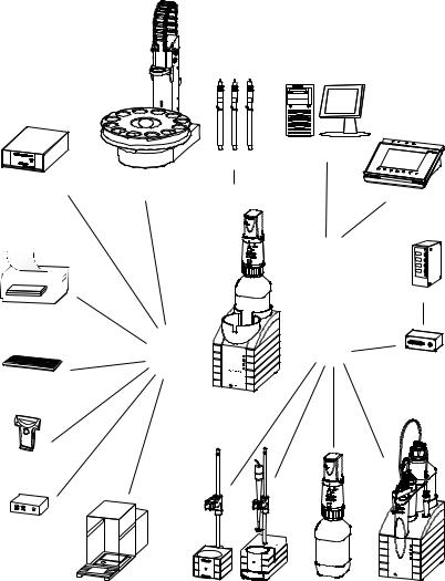
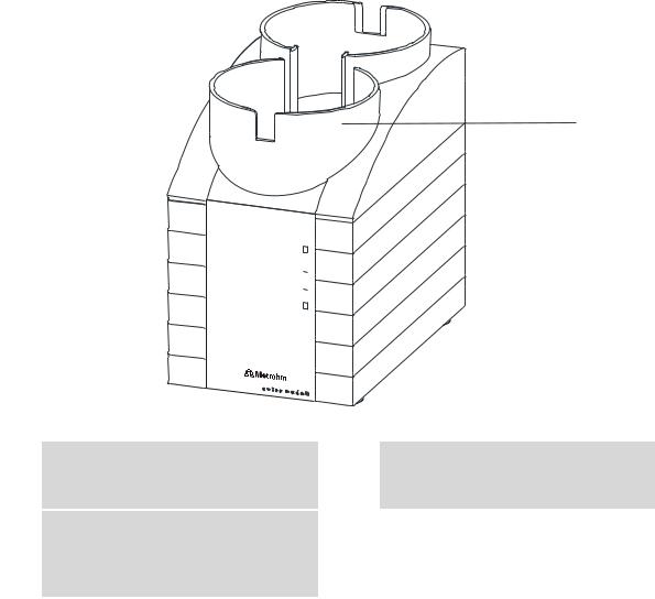
1.1The Titrando system
The Titrando is the heart of the modular Titrando system. Operation is carried out either by Touch Control with a touch-sensitive screen ("standalone titrator") or by a computer with a corresponding software.
A Titrando system can contain numerous kinds of a variety of instruments. The following figure provides an overview of the peripheral devices you can connect to the 851 Titrando.
Dosing Interface
Printer
PC keyboard
Barcode
reader
USB hub
Figure 1
|
|
|
Computer |
|
|
Sensors |
|
USB Sample Processor |
|
|
|
Robotic Titrosampler |
Input 1 / 2 |
Touch Control |
|
|
|
||
|
|
|
Controller |
|
|
|
Relay Box |
|
USB |
|
MSB |
|
|
|
Remote Box |
|
Converter |
Titrando |
|
|
|
|
|
|
232 |
|
|
USB/RS |
- |
|
|
|
|
|
|
|
|
|
8mDi50soa |
|
|
|
Mrothe |
Balance |
Stirrer / Ti Stand |
Dosino |
Dosimat |
The Titrando system
851 Titrando |
1 |
1.2 Instrument description |
|
Up to three control instruments (Titrando, Dosing Interface, USB Sample Processor, etc.) can be controlled via USB connection during operation with the 900 Touch Control.
You can request information on special applications in the "Application Bulletins" and "Application Notes", available free of charge through the responsible Metrohm representative. Various monographs on the subjects of titration techniques and electrodes are also available.
Updating the device software is described in the Help for the corresponding PC software.
1.2Instrument description
The 851 Titrando has the following characteristics:
Operation
Operation is carried out by means of a touch-sensitive Touch Control or with high-performance PC software.
MSB connectors
Four MSB connectors (Metrohm Serial Bus) for connecting dosing devices (Dosimat with exchange unit or Dosino with dosing unit), stirrers, titration stands and Remote Boxes.
USB connectors
Two USB connectors, through which devices such as printers, PC keyboards, barcode readers or additional control instruments (USB Sample Processor, Titrando, Dosing Interface, etc.) can be connected.
Measuring interface
One measuring input each for:
–a generator electrode
–a temperature sensor (Pt1000 or NTC)
–a double Pt electrode
1.3Titration modes – Measuring modes – Dosing commands
The 851 Titrando supports the following titration modes, measuring modes and dosing commands:
KFC
Coulometric water content determination according to Karl Fischer. Measuring mode:
–Ipol (voltametric measurement with selectable polarization current)
2 |
851 Titrando |
|
1 Introduction |
BRC
Coulometric bromine index determination. Determining the amount of double bonds in mineral oils, for example.
Measuring mode:
–Ipol (voltametric measurement with selectable polarization current)
MEAS
The following measuring modes can be selected for measurements:
–T (temperature measurement)
Dosing commands
The following commands for dosing can be selected:
–PREP (rinsing the cylinder and tubings of an exchange unit or dosing unit)
–EMPTY (emptying the cylinder and tubings of a dosing unit)
–ADD (dosing a specified volume)
–LQH (carrying out complex dosing tasks with a Dosino)
1.4About the documentation
CAUTION
Please read through this documentation carefully before putting the instrument into operation. The documentation contains information and warnings which the user must follow in order to ensure safe operation of the instrument.
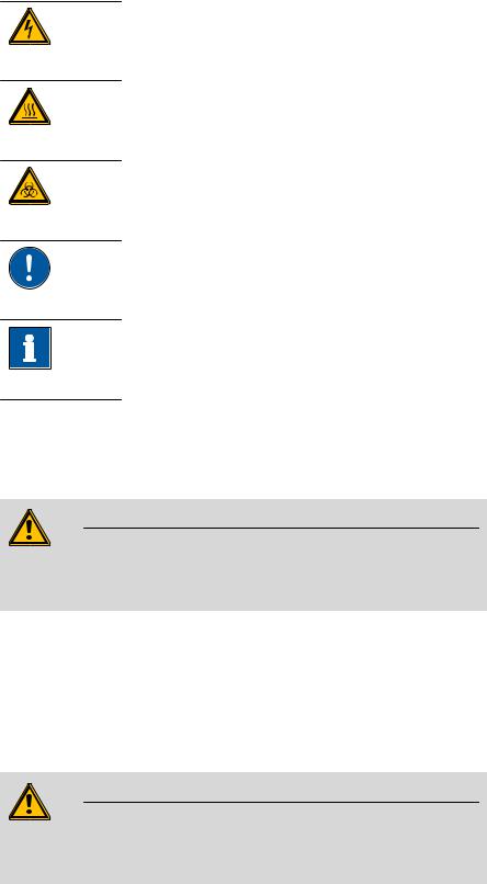
1.4.1Symbols and conventions
The following symbols and formatting may appear in this documentation:
|
Cross-reference to figure legend |
|
The first number refers to the figure number, the sec- |
|
ond to the instrument part in the figure. |
|
|
|
Instruction step |
|
Carry out these steps in the sequence shown. |
|
|
Method |
Dialog text, parameter in the software |
|
|
File New |
Menu or menu item |
|
|
[Next] |
Button or key |
|
|
|
WARNING |
|
This symbol draws attention to a possible life-threat- |
|
ening hazard or risk of injury. |
|
|
851 Titrando |
3 |
1.5 Safety instructions |
|
WARNING
This symbol draws attention to a possible hazard due to electrical current.
WARNING
This symbol draws attention to a possible hazard due to heat or hot instrument parts.
WARNING
This symbol draws attention to a possible biological hazard.
CAUTION
This symbol draws attention to possible damage to instruments or instrument parts.
NOTE
This symbol highlights additional information and tips.
1.5Safety instructions
1.5.1General notes on safety
WARNING
This instrument may only be operated in accordance with the specifications in this documentation.
This instrument has left the factory in a flawless state in terms of technical safety. To maintain this state and ensure non-hazardous operation of the instrument, the following instructions must be observed carefully.
1.5.2Electrical safety
The electrical safety when working with the instrument is ensured as part of the international standard IEC 61010.
WARNING
Only personnel qualified by Metrohm are authorized to carry out service work on electronic components.
4 |
851 Titrando |
|
1 Introduction |
WARNING
Never open the housing of the instrument. The instrument could be damaged by this. There is also a risk of serious injury if live components are touched.
There are no parts inside the housing which can be serviced or replaced by the user.
Mains voltage
WARNING
An incorrect mains voltage can damage the instrument.
Only operate this instrument with a mains voltage specified for it (see rear panel of the instrument).
Protection against electrostatic charges
WARNING
Electronic components are sensitive to electrostatic charges and can be destroyed by discharges.
Do not fail to pull the mains cable out of the mains connection socket before you set up or disconnect electrical plug connections at the rear of the instrument.
1.5.3Working with liquids
CAUTION
Periodically check all system connections for leaks. Observe the relevant regulations in respect to working with flammable and/or toxic fluids and their disposal.
851 Titrando |
5 |
1.5 Safety instructions |
|
1.5.4Flammable solvents and chemicals
WARNING
All relevant safety measures are to be observed when working with flammable solvents and chemicals.
Set up the instrument in a well-ventilated location (e.g. fume cupboard).
Keep all sources of flame far from the workplace.
Clean up spilled liquids and solids immediately.
Follow the safety instructions of the chemical manufacturer.
1.5.5Recycling and disposal
This product is covered by European Directive 2002/96/EC, WEEE – Waste from Electrical and Electronic Equipment.
The correct disposal of your old equipment will help to prevent negative effects on the environment and public health.
More details about the disposal of your old equipment can be obtained from your local authorities, from waste disposal companies or from your local dealer.
6 |
851 Titrando |
|
2 Overview of the instrument |
2 Overview of the instrument
1
On 


Gen. 


2
3
851 Titrando
Figure 2 Front 851 Titrando
1Bottle holder
With holding clamps, for two reagent bottles.
3"Gen." LED
Lights up when the Titrando is ready for operation and the generator electrode is connected.
2"On" LED
Lights up when the Titrando is ready for operation.
851 Titrando |
7 |

1 |
6 |
2 |
|
3 |
7 |
|
|
4 |
|
|
8 |
5 |
9 |
Figure 3 Rear 851 Titrando
1 |
Type plate |
|
2 |
USB connector (USB 1 and USB 2) |
|
Contains specifications concerning supply |
|
|
USB ports (type A) for connecting printer, |
|
voltage, instrument type and serial number. |
|
|
keyboard, barcode reader, additional Titran- |
|
|
|
|
dos, USB Sample Processor, etc. |
|
|
|
|
|
3Connector (Controller)
For connecting a Touch Control or a PC with installed PC software. Mini DIN, 9-pin.
4MSB connector (MSB 1 to MSB 4)
Metrohm Serial Bus. For connecting external dosing devices, stirrers or Remote Boxes. Mini DIN, 9-pin.
5 |
Power socket |
|
6 |
Measuring interface 1 (Input 1) |
|
|
|
|
|
|
|
|
|
|
7 |
Electrode connector (Gen.) |
|
8 |
Temperature sensor connector (Temp.) |
|
For connecting a generator electrode. |
|
|
For connecting temperature sensors (Pt1000 |
|
|
|
|
or NTC). Two B sockets, 2 mm. |
|
|
|
|
|
9Electrode connector (Ind.)
For connecting a double Pt electrode. Socket F.
8 |
851 Titrando |
|
3 Installation |
3 Installation
3.1Setting up the instrument
3.1.1Packaging
The instrument is supplied in highly protective special packaging together with the separately packed accessories. Keep this packaging, as only this ensures safe transportation of the instrument.
3.1.2Checks
Immediately after receipt, check whether the shipment has arrived complete and without damage by comparing it with the delivery note.
3.1.3Location
The instrument has been developed for operation indoors and may not be used in explosive environments.
Place the instrument in a location of the laboratory which is suitable for operation, free of vibrations, protected from corrosive atmosphere, and contamination by chemicals.
The instrument should be protected against excessive temperature fluctuations and direct sunlight.
3.2Connecting a controller
3.2.1Operation
Two different versions are available for operating the 851 Titrando:
A Touch Control with touch-sensitive screen. It forms a "stand-alone instrument" together with the 851 Titrando.
A computer enables operation of the 851 Titrando with the help of a PC software, e.g. tiamo.
CAUTION
Take care to ensure that the power supply cable is pulled out of the power socket before either setting up or disconnecting connections between the instruments.
851 Titrando |
9 |
3.2 Connecting a controller |
|
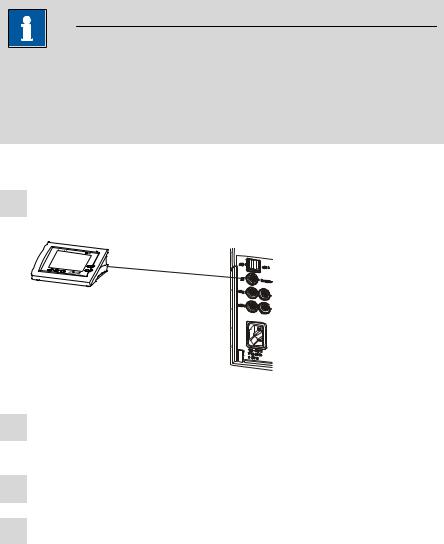
3.2.1.1Connecting a Touch Control
NOTE
The plug is protected against accidental disconnection of the cable by means of a pull-out protection feature. If you wish to pull out the plug, you will first need to pull back the outer plug sleeve marked with arrows.
Connect the Touch Control as follows:
1Insert the plug of the Touch Control connection cable into the
Controller socket.
Figure 4 Connecting the Touch Control
2Connect the MSB devices (see Chapter 3.3, page 13).Connect the USB devices (see Chapter 3.4, page 17).
3Connect the Titrando to the power supply.
4Switch on the Touch Control.
The Touch Control power supply is supplied through the Titrando. Automatic system tests are performed on both instruments at the time of activation. The On LED on the front of the Titrando lights up when the system test has been completed and the instrument is ready for operation.
10 |
851 Titrando |

|
3 Installation |
CAUTION
The Touch Control must be shut down properly by deactivation with the power switch on the rear of the instrument before the power supply is interrupted. If this is not done, then there is a danger of data loss. Because of the fact that the power supply for the Touch Control is provided through the Titrando, you must never disconnect the Titrando from the power supply (e.g. by deactivating with a connector strip) before you have deactivated the Touch Control.
If you would prefer not to position the Touch Control directly next to the Titrando, then you can lengthen the connection with the 6.2151.010 cable. The maximum connection length permitted is 5 m.
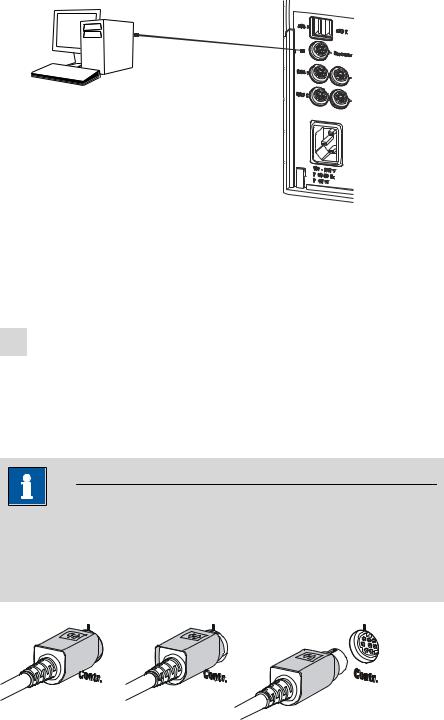
3.2.1.2Connecting a computer
The 851 Titrando requires a USB connection to a computer in order to be able to be controlled by a PC software. Using a 6.2151.000 controller cable, the instrument can be connected directly, either to a USB socket on a computer, to a connected USB hub or to a different Metrohm control device.
You need administrator rights for the installation of driver software and control software on your computer.
Cable connection and driver installation
A driver installation is required in order to ensure that the 851 Titrando is recognized by the PC software. To accomplish this, you must comply with the procedures specified. The following steps are necessary:
1Installing the software
Insert the PC software installation CD and carry out the installation program directions.
Exit the program if you have started it after the installation.
2Establishing the cable connections
Connect all peripheral devices to the instrument, see Chapter 3.3, page 13 and see Chapter 3.4, page 17.
Connect the instrument to the power supply if you have not already done this.
The "On" LED on the 851 Titrando is not yet illuminated!
Connect the instrument to a USB connector (Type A) of your computer (see manual of your computer). The 6.2151.000 cable is used for this purpose.
851 Titrando |
11 |
3.2 Connecting a controller
6.2151.000
Figure 5 Connecting the computer
The instrument is recognized. Depending on the version of the Windows operating system used, the driver installation proceeds differently afterwards. Either the necessary driver software is installed automatically or an installation wizard is started.
3Follow the instructions of the installation wizard.
The "On" LED on the 851 Titrando lights up when the driver installation has been completed and the instrument is ready for operation.
If problems should occur during installation, contact your company's IT support team.
NOTE
The plug on the instrument end of the 6.2151.000 controller cable is protected against accidental disconnection by means of a pull-out protection feature. If you wish to pull out the plug, you will first need to pull back the outer plug sleeve marked with arrows.
Registering and configuring the instrument in the PC software
The instrument must be registered in the configuration of your PC software. Once that has been done, you can then configure it according to your requirements. Proceed as follows:
12 |
851 Titrando |
|
3 Installation |
1Setting up the instrument
Start the PC software.
The instrument is automatically recognized. The configuration dialog for the instrument is displayed.
Make configuration settings for the instrument and its connectors.
More detailed information concerning the configuration of the instrument can be found in the documentation for the respective PC software.
3.3Connecting MSB devices
In order to connect MSB devices, e.g. stirrers or dosing devices, Metrohm instruments are equipped with up to a maximum of four connectors on what is referred to as the Metrohm Serial Bus (MSB). Various kinds of peripheral devices can be connected in sequence (in series, as a
"daisy chain") at a single MSB connector (8-pin Mini DIN socket) and controlled simultaneously by the respective control device. In addition to the connection cable, stirrers and the Remote Box are each equipped with their own MSB socket for this purpose.
The following figure provides an overview of the instruments that can be connected to an MSB socket, along with a number of different cabling variations.
Stirrer / Ti Stand 

MSB
Remote Box
Ti Stand / Stirrer
Relay Box
Dosino / Dosimat
Dosino
Dosimat
Dosimat / Dosino
Figure 6 MSB connections
The control device determines which peripheral devices are supported.
851 Titrando |
13 |
3.3 Connecting MSB devices |
|
NOTE
When connecting MSB devices together, the following must be observed:
Only one device of the same type can be used at a single MSB connector at one time.
Type 700 Dosino and 685 Dosimat dosing devices cannot be connected together with other MSB instruments on a shared connector. These dosing devices must be connected separately.
CAUTION
Exit the control software before you plug in MSB instruments. When it is switched on, the control device automatically recognizes which device is connected to which MSB connector. The operating unit or the control software enters the connected MSB devices into the system configuration (device manager).
MSB connections can be extended with the 6.2151.010 cable. The maximum connection length permitted is 15 m.
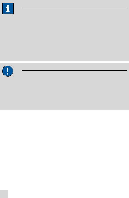
3.3.1Connecting a dosing device
Four dosing devices can be connected to the instrument (MSB 1 to MSB 4).
The types of dosing devices that are supported are:
800 Dosino
700 Dosino
805 Dosimat
685 Dosimat
Proceed as follows:
1Connecting a dosing device
Exit the control software.
Connect the connection cable of the dosing device to one of the sockets marked with MSB on the rear of the control device.
Start the control software.
14 |
851 Titrando |

|
3 Installation |
Figure 7 Connecting a dosing device
3.3.2Connecting a stirrer or titration stand
You can use the following instruments:
With built-in magnetic stirrer (stirring "from below"):
–801 Stirrer
–803 Ti Stand
Without built-in magnetic stirrer (stirring "from above"):
–804 Ti Stand with propeller stirrer 802 Stirrer
Connect a stirrer or a titration stand as follows:
1Connecting the stirrer or titration stand
Exit the control software.
Connect the connection cable of the magnetic stirrer or of the titration stand to one of the sockets marked with MSB on the rear of the control device.
804 Ti Stand only: Connect the propeller stirrer to the stirrer connector (socket with stirrer symbol) of the titration stand.
Start the control software.
851 Titrando |
15 |
3.3 Connecting MSB devices |
|
Figure 8 Connecting an MSB stirrer
Figure 9 Connecting the propeller stirrer to the titration stand
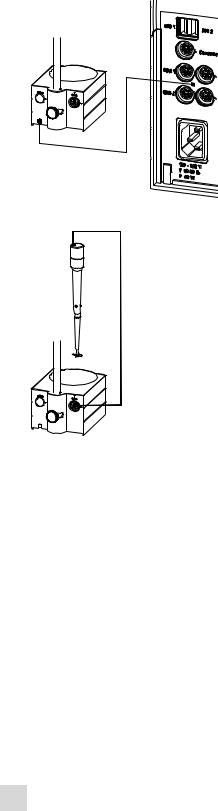
3.3.3Connecting a Remote Box
Instruments that are controlled via remote lines and/or that send control signals via remote lines can be connected via the 6.2148.010 Remote Box. In addition to Metrohm, other instrument manufacturers also use similar connectors that make it possible to connect different instruments together. These interfaces are also frequently given the designations "TTL Logic", "I/O Control" or "Relay Control" and generally have a signal level of 5 volts.
Control signals are understood to be electrical line statuses or electrical pulses (> 200 ms) which display the operating status of an instrument or which trigger or report an event. Sequences on a variety of instruments can thus be coordinated in a single complex automation system. No exchange of data is possible, however.
Proceed as follows:
1Connecting the Remote Box
Exit the control software.
16 |
851 Titrando |
|
3 Installation |
Connect the Remote Box connection cable to one of the sockets marked with MSB on the rear of the control device.
Start the control software.
Figure 10 Connecting the Remote Box
You can, for example, connect an 849 Level Control (fill level monitoring in a canister) or a 731 Relay Box (switch box for 230/110 volt alternating current sockets and low-voltage direct current outlets). The Remote Box also has an MSB socket at which a further MSB device, e.g. a dosing device or a stirrer, can be connected.
You will find precise information concerning the pin assignment of the interface on the Remote Box in the appendix.
3.4Connecting USB devices
3.4.1General
The 851 Titrando has two USB connectors (type A sockets) for peripheral devices with USB interfaces. The Titrando functions as a USB hub (distributor) no matter how it is operated. If you wish to connect more than two devices to the USB, you can also use an additional, commercially available USB hub.
CAUTION
If you operate the 851 Titrando with the aid of the Touch Control, take care to ensure that the Touch Control is switched off when you set up or disconnect connections between the various instruments. If you use a PC software to control the 851 Titrando, you should exit the program before you set up or disconnect the USB connections.
851 Titrando |
17 |

3.4 Connecting USB devices |
|
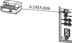
3.4.2Connecting a USB hub
If you wish to connect more than two devices to the USB connector of the 851 Titrando, you can also use an additional commercially available USB hub (distributor). If you operate the 851 Titrando with the help of the Touch Control, then you should use a USB hub with its own power supply.
Connect the USB hub as follows:
1 Switch off the Touch Control and/or exit the PC software.
2With the aid of the 6.2151.020 cable, connect the USB connector of the 851 Titrando (type A) with the USB connector of the hub (type B, see manual for the hub).
3Switch on the Touch Control.
The USB hub is recognized automatically.
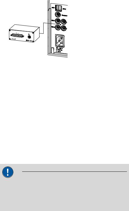
3.4.3Connecting a printer
Printers that are connected to the 851 Titrando with Touch Control must meet the following requirements:
Printer languages: HP-PCL (PCL 3 to 5, PCL 3GUI), Canon BJL Commands or Epson ESC P/2
Printer resolution: 300 dots/inch or 360 dots/inch (Epson)
Paper size: A4 or Letter, single-sheet feed.
Connect the printer as follows:
1 Switch off the Touch Control.
2With the aid of the 6.2151.020 cable, connect the USB connector of the 851 Titrando (type A) with the USB connector of the printer (type B, see manual for the printer).
3 Switch on the printer first, then the Touch Control.
4Configure the printer in the device manager of the Touch Control (see Touch Control manual).
18 |
851 Titrando |
|
3 Installation |
Figure 11 Connecting a printer
3.4.4Connecting a balance
Operation with a PC software:
–Connect the balance directly to the serial connector (COM) of the computer. This is usually 9-pin and marked with the symbol
IOIOI.
Operation with Touch Control:
–You will need the 6.2148.050 USB/RS-232 adapter to connect a balance.
The following table offers an overview of the balances that you can use together with the 851 Titrando and of which cable you will need for connection to the RS-232 interface:
Balance |
Cable |
|
|
|
|
AND ER, FR, FX with RS-232 inter- |
6.2125.020 + 6.2125.010 |
|
face (OP-03) |
|
|
|
|
|
Mettler AB, AG, PR (LC-RS9) |
In the scope of delivery for the |
|
|
balance |
|
|
|
|
Mettler AM, PM, PE with interface |
6.2146.020 + 6.2125.010 |
|
option 016 |
Also from Mettler: ME 47473 |
|
|
||
or |
adapter and either ME 42500 |
|
Mettler AJ, PJ with interface |
hand switch or ME 46278 foot |
|
switch |
||
option 018 |
||
|
||
|
|
|
Mettler AT |
6.2146.020 + 6.2125.010 |
|
|
Also from Mettler: ME 42500 |
|
|
hand switch or ME 46278 foot |
|
|
switch |
|
|
|
|
Mettler AX, MX, UMX, PG, AB-S, |
6.2134.120 |
|
PB-S, XP, XS |
|
|
|
|
851 Titrando |
19 |

3.4 Connecting USB devices |
|
|
|
|
|
|
Balance |
Cable |
|
|
|
|
Mettler AE with interface option |
6.2125.020 + 6.2125.010 |
|
011 or 012 |
Also from Mettler: ME 42500 |
|
|
|
|
|
hand switch or ME 46278 foot |
|
|
switch |
|
|
|
|
Ohaus Voyager, Explorer, Analyti- |
Cable AS017-09 from Ohaus |
|
cal Plus |
|
|
|
|
|
Precisa balances with RS-232-C |
6.2125.080 + 6.2125.010 |
|
interface |
|
|
|
|
|
Sartorius MP8, MC, LA, Genius, |
6.2134.060 |
|
Cubis |
|
|
|
|
|
Shimadzu BX, BW |
6.2125.080 + 6.2125.010 |
|
|
|
Operation with Touch Control
Connect the balance as follows:
1Plug in the USB plug of the USB/RS-232 adapter at the USB connector of the 851 Titrando.
2Connect the RS-232 interface of the USB/RS-232 adapter with the RS-232 interface of the balance (see table for cable).
3 Switch on the Touch Control.
4 Switch on the balance.
5 Activate the RS-232 interface of the balance if necessary.
6Configure the RS-232 interface of the USB/RS-232 adapter in the device manager of the Touch Control (see Touch Control manual).
3.4.5Connecting a PC keyboard (only for operation with Touch Control)
The PC keyboard is used as an aid for text and numerical input.
Connect the PC keyboard as follows:
1Insert the USB plug of the keyboard into one of the USB sockets of the 851 Titrando.
20 |
851 Titrando |

|
3 Installation |
2Switch on the Touch Control.
The keyboard is recognized automatically and entered in the device manager.
3Configure the keyboard in the device manager of the Touch Control (see Touch Control manual).
3.4.6Connecting a barcode reader
The barcode reader is used as an aid for text and numerical input. You can connect a barcode reader with USB interface.
Operation with Touch Control
Connect the barcode reader as follows:
1Insert the USB plug of the barcode reader into one of the USB sockets of the 851 Titrando.
2Switch on the Touch Control.
The barcode reader is recognized automatically and entered in the device manager.
3Configure the barcode reader in the device manager of the Touch Control (see Touch Control manual).
Settings on the barcode reader:
Program the barcode reader as follows (see also the manual for the barcode reader):
1 Switch the barcode reader to programming mode.
2Specify the desired layout for the keyboard (USA, Germany, France, Spain, German-speaking Switzerland).
This setting must match the setting in the device manager (see the Touch Control manual).
3Make sure that the barcode reader is set in such a way that Ctrl characters (ASCII 00 to 31) can be sent.
851 Titrando |
21 |

3.4 Connecting USB devices |
|
4Program the barcode reader in such a way that the ASCII character 02 (STX or Ctrl B) is sent as the first character. This first character is normally referred to as the "Preamble" or "Prefix Code".
5Program the barcode reader in such a way that the ASCII character 04 (EOT or Ctrl D) is sent as the last character. This last character is normally referred to as the "Postamble", "Record Suffix" or "Postfix Code".
6 Exit the programming mode.
22 |
851 Titrando |
Loading...