


 Loading...
874 Oven Sample Processor
Manual
8.874.8002EN

Metrohm AG CH-9101 Herisau Switzerland
Phone +41 71 353 85 85 Fax +41 71 353 89 01 info@metrohm.com www.metrohm.com
874 Oven Sample Processor
Manual
8.874.8002EN |
06/2011 dm |
Teachware Metrohm AG CH-9101 Herisau
teachware@metrohm.com
This documentation is protected by copyright. All rights reserved.
Although all the information given in this documentation has been checked with great care, errors cannot be entirely excluded. Should you notice any mistakes please send us your comments using the address given above.
|
Table of contents |
Table of contents
1 Introduction |
1 |
|
1.1 |
Instrument description ......................................................... |
1 |
1.1.1 |
Instrument versions ................................................................. |
1 |
1.1.2 |
Instrument components .......................................................... |
2 |
1.1.3 |
Intended use ........................................................................... |
2 |
1.2 |
About the documentation ................................................... |
3 |
1.2.1 |
Notation and Pictograms ......................................................... |
3 |
1.3 |
Safety instructions ................................................................ |
4 |
1.3.1 |
General notes on safety ........................................................... |
4 |
1.3.2 |
Electrical safety ........................................................................ |
4 |
1.3.3 |
Tubing and capillary connections ............................................. |
5 |
1.3.4 |
Personnel safety ...................................................................... |
5 |
1.3.5 |
Flammable solvents and chemicals ........................................... |
7 |
1.3.6 |
Recycling and disposal ............................................................. |
7 |
2 Overview of the instrument |
8 |
|
3 Installation |
|
12 |
3.1 |
Setting up the instrument .................................................. |
12 |
3.1.1 |
Packaging .............................................................................. |
12 |
3.1.2 |
Checks .................................................................................. |
12 |
3.1.3 |
Location ................................................................................ |
12 |
3.2 |
Connecting a mains cable .................................................. |
12 |
3.3 |
Mounting the sample insert .............................................. |
13 |
3.4 |
Mounting the needles ........................................................ |
14 |
3.5 |
Mounting the heating tube ............................................... |
17 |
3.6 |
Mounting the drying flasks ............................................... |
18 |
3.7 |
Mounting the dust filter .................................................... |
20 |
3.8 |
Mounting the air/nitrogen connector ............................... |
20 |
3.9 |
Mounting the safety shield ................................................ |
22 |
3.10 |
Mounting the KF titration cell ........................................... |
23 |
3.11 |
Inserting the heating tube into the KF titration cell ....... |
24 |
3.12 |
Attaching the sample rack ................................................. |
27 |
3.13 |
Adjusting the guide rod ..................................................... |
28 |
3.14 |
Connecting a computer ..................................................... |
28 |
3.15 |
Connecting MSB devices ................................................... |
30 |
3.15.1 |
Connecting dosing devices .................................................... |
31 |
874 Oven Sample Processor |
III |
Table of contents |
|
|
|
|
|
3.15.2 Connecting a stirrer or titration stand .................................... |
|
32 |
|
|
3.15.3 Connecting a remote box ...................................................... |
|
33 |
|
|
3.16 |
Connecting USB devices ..................................................... |
|
34 |
|
3.16.1 Connecting a barcode reader ................................................. |
|
34 |
|
4 Processing a sample series |
|
36 |
||
5 |
Handling and maintenance |
|
37 |
|
|
5.1 |
General ................................................................................ |
|
37 |
|
5.2 |
Care ...................................................................................... |
|
37 |
|
5.3 |
Quality Management and validation with Metrohm ....... |
37 |
|
6 |
Troubleshooting |
|
39 |
|
|
6.1 |
Problems and their solutions ............................................. |
|
39 |
7 |
Appendix |
|
|
40 |
|
7.1 |
Remote interface ................................................................ |
|
40 |
|
7.1.1 Pin assignment of the remote interface .................................. |
|
40 |
|
|
7.2 |
Stirring rate ......................................................................... |
|
42 |
8 |
Technical specifications |
|
43 |
|
|
8.1 |
Lift and turntable ............................................................... |
|
43 |
|
8.2 |
Oven ..................................................................................... |
|
43 |
|
8.3 |
Gas flow .............................................................................. |
|
43 |
|
8.4 |
Outlet heater ....................................................................... |
|
44 |
|
8.5 |
Interfaces and connectors ................................................. |
|
44 |
|
8.6 |
Mains connection ............................................................... |
|
44 |
|
8.7 |
Safety specifications ........................................................... |
|
44 |
|
8.8 |
Electromagnetic compatibility (EMC) |
................................ |
45 |
|
8.9 |
Ambient temperature ......................................................... |
|
45 |
|
8.10 |
Reference conditions .......................................................... |
|
46 |
|
8.11 |
Dimensions .......................................................................... |
|
46 |
9 |
Conformity and warranty |
|
47 |
|
|
9.1 |
Declaration of Conformity ................................................. |
|
47 |
|
9.2 |
Quality Management Principles ........................................ |
|
48 |
|
9.3 |
Warranty (guarantee) ......................................................... |
|
49 |
10 Accessories |
|
|
51 |
|
|
10.1 |
Scope of delivery 2.874.0010 ............................................ |
|
51 |
IV |
874 Oven Sample Processor |
|
|
Table of contents |
10.2 |
Scope of delivery 2.874.0020 |
............................................ 59 |
10.3 |
Optional accessories ........................................................... |
66 |
Index |
|
70 |
874 Oven Sample Processor |
V |
Table of figures |
|
Table of figures |
|
|
Figure 1 |
Front 874 Oven Sample Processor ..................................................... |
8 |
Figure 2 |
Rear 874 Oven Sample Processor .................................................... |
10 |
Figure 3 |
6.2041.720 sample rack .................................................................. |
11 |
Figure 4 |
Connecting the mains cable ............................................................ |
12 |
Figure 5 |
Mounting the sample insert ............................................................. |
13 |
Figure 6 |
Mounting the needles ..................................................................... |
15 |
Figure 7 |
Mounting the tubing ....................................................................... |
16 |
Figure 8 |
Mounting the heating tube ............................................................. |
17 |
Figure 9 |
Preparing the drying flasks ............................................................... |
18 |
Figure 10 |
Mounting the tubings ..................................................................... |
19 |
Figure 11 |
Mounting the dust filter .................................................................. |
20 |
Figure 12 |
External gas connector .................................................................... |
21 |
Figure 13 |
Mounting the safety shield .............................................................. |
22 |
Figure 14 |
Coulometric KF titration cell ............................................................ |
25 |
Figure 15 |
Volumetric KF titration cell .............................................................. |
26 |
Figure 16 |
Attaching the rack ........................................................................... |
27 |
Figure 17 |
Adjusting the guide rod ................................................................... |
28 |
Figure 18 |
Connecting the computer ............................................................... |
29 |
Figure 19 |
Connecting a dosing device ............................................................. |
32 |
Figure 20 |
Connecting MSB stirrer .................................................................... |
32 |
Figure 21 |
Rod Stirrer and titration stand .......................................................... |
33 |
Figure 22 |
Connecting a remote box ................................................................ |
33 |
Figure 23 |
USB connectors ............................................................................... |
34 |
Figure 24 |
Connectors of the remote box ......................................................... |
40 |
Figure 25 |
Pin assignment of the remote socket and plug ................................ |
40 |
Figure 26 |
Rotational speed depending on stirring rate .................................... |
42 |
VI |
874 Oven Sample Processor |
|
1 Introduction |
1 Introduction
1.1Instrument description
The 874 Oven Sample Processor is used whenever the heating up of a sample and/or the thermal expulsion of moisture in solid substances or liquids is required. In combination with a coulometric or volumetric KF titrator, the 874 Oven Sample Processor is the ideal analysis system for water determination in samples that contain disruptive components or from which moisture can be removed only with difficulty.
One of its decisive advantages is the reduction of sample preparation to a minimum. Thanks to the use of hermetically sealed sample vessels ("headspace vials"), the filling of the samples can be accomplished directly onsite. The PTFE-coated septa guarantee a constant, non-falsified water content, even after prolonged holding times.
The sample heated in the oven module releases its moisture in the form of water vapor, which is conveyed into a measuring cell with the aid of a gas flow. An air pump is installed for the purpose of generating the gas flow.
An inlet valve is available for nitrogen or other inert gases. The determination of the moisture can be accomplished in the measuring cell either coulometrically or volumetrically according to Karl Fischer.
The operation and control of the 874 Oven Sample Processor is accomplished by means of the tiamo™ PC software. This enables convenient programming of method runs, ranging from the simple to the complex. The integration of the 874 Oven Sample Processor together with other instruments (e. g. with a coulometer) using one user interface, makes not only simple operation possible, but also the evaluation and storage of the measurement data from all of the linked instruments in one single database.
1.1.1Instrument versions
The 874 Oven Sample Processor is available in two versions with different accessories.
Version 2.874.0010 with accessories for the usage of standard vials (volume 6 mL)
Version 2.874.0020 without accessories for the usage of standard vials. Appropriate accessories can be ordered for specific vessel sizes.
874 Oven Sample Processor |
1 |
1.1 Instrument description |
|
1.1.2Instrument components
The 874 Oven Sample Processor has the following components:
Oven
Oven module made of aluminum with software-operated temperature control for heating the sample vessel.
Fan
Propeller fan for cooling the oven module.
Inlet valve
Valve for switching over the source of the gas flow.
Air pump
Pump for generating the gas flow.
Outlet heater
Heating tube for preventing the condensation of moisture.
Lift with rods
Guidance device with needle adapter and tubing for the gas flow.
Turntable
For the standard sample rack with a capacity of 36 sample vials (6 mL) or the special sample rack with a capacity of 25 sample vials ( = 16 ...
32 mm).
1.1.3Intended use
The 874 Oven Sample Processor is designed for usage as an auxiliary device for sample preparation in analytical laboratories. Its main area of application is the moisture determination according to Karl Fischer (coulometric or volumetric). The 874 Oven Sample Processor enables the application of thermal gas extraction technique.
The present instrument is suitable for processing chemicals and flammable samples. The usage of the 874 Oven Sample Processor therefore requires that the user has basic knowledge and experience in the handling of toxic and caustic substances. Knowledge with respect to the application of the fire prevention measures prescribed for laboratories is also mandatory.
2 |
874 Oven Sample Processor |
|
1 Introduction |
1.2About the documentation
Caution
Please read through this documentation carefully before putting the instrument into operation. The documentation contains information and warnings which have to be followed by the user in order to ensure safe operation of the instrument.
1.2.1Notation and Pictograms
The following notations and pictograms (symbols) are used in these
Instructions for Use:
Cross-reference to illustration legend number
The first number stands for the number of the illustration, the second for the legend number.
|
Instruction step |
|
Follow these steps. |
|
|
Methode |
Dialog, Parameter in the soft- |
|
ware |
|
|
[Weiter] |
Button in the software or Key on |
|
the keyboard. |
|
|
|
Warning |
|
This symbol draws attention to a |
|
possilbe danger of life or injury. |
|
|
|
Warning |
|
This symbol draws attention to a |
|
possilbe danger through electrical |
|
current. |
|
|
|
Warning |
|
This symbol draws attention to a |
|
possible danger through heat or |
|
hot instrument parts. |
874 Oven Sample Processor |
3 |
1.3 Safety instructions |
|
Warning
This symbol draws attention to a possible biological hazard.
Caution
This symbol draws attention to possible damage of instruments or instrument parts.
Comment
This symbol marks additional information and tips.
1.3Safety instructions
1.3.1General notes on safety
Warning
This instrument may only be operated in accordance with the specifications in this documentation.
This instrument has left the factory in a flawless state in terms of technical safety. To maintain this state and ensure non-hazardous operation of the instrument, the following instructions must be observed carefully.
1.3.2Electrical safety
The electrical safety when working with the instrument is ensured as part of the international standard IEC 61010.
Warning
Only personnel qualified by Metrohm are authorized to carry out service work on electronic components.
Warning
Never open the housing of the instrument. The instrument could be damaged by this. There is also a risk of serious injury if live components are touched.
There are no parts inside the housing which can be serviced or replaced by the user.
4 |
874 Oven Sample Processor |
|
1 Introduction |
Mains voltage
Warning
An incorrect mains voltage can damage the instrument.
Only operate this instrument with a mains voltage specified for it (see rear panel of the instrument).
Protection against electrostatic charges
Warning
Electronic components are sensitive to electrostatic charges and can be destroyed by discharges.
Always pull the mains cable out of the mains connection socket before connecting or disconnecting electrical appliances on the rear panel of the instrument.
1.3.3Tubing and capillary connections
Caution
Leaks in tubing and capillary connections are a safety risk. Tighten all connections well by hand. Avoid applying excessive force to tubing connections. Damaged tubing ends lead to leakage. Appropriate tools can be used to loosen connections.
Check the connections regularly for leakage. If the instrument is used mainly in unattended operation, then weekly inspections are mandatory.
1.3.4Personnel safety
Warning
Wear protective goggles and working clothes suitable for laboratory work while operating the 874 Oven Sample Processor. It is also advisable to wear gloves when caustic liquids are used or in situations where glass vessels could break.
874 Oven Sample Processor |
5 |

1.3 Safety instructions |
|
Warning
Always install the safety shield supplied with the equipment before using the instrument for the first time. Pre-installed safety shields are not allowed to be removed.
The 874 Oven Sample Processor may not be operated without a safety shield!
Warning
Personnel are not permitted to reach into the working area of the instrument while operations are running!
A considerable risk of injury exists for the user.
Warning
In the event of a possible blockage of a drive, the mains plug must be pulled out of the socket immediately. Do not attempt to free jammed sample vessels or other parts while the device is switched on. Blockages can only be cleared when the instrument is in a voltage-free status; this action generally involves a considerable risk of injury.
Warning
The 874 Oven Sample Processor is not suitable for utilization in biochemical, biological or medical environments in its basic equipment version.
Appropriate protective measures must be implemented in the event that potentially infectious samples or reagents are being processed.
6 |
874 Oven Sample Processor |

|
1 Introduction |
1.3.5Flammable solvents and chemicals
Warning
All relevant safety measures are to be observed when working with flammable solvents and chemicals.
Set up the instrument in a well-ventilated location.
Keep all sources of flame far from the workplace.
Clean up spilled fluids and solids immediately.
Follow the safety instructions of the chemical manufacturer.
1.3.6Recycling and disposal
This product is covered by European Directive 2002/96/EC, WEEE – Waste from Electrical and Electronic Equipment.
The correct disposal of your old equipment will help to prevent negative effects on the environment and public health.
More details about the disposal of your old equipment can be obtained from your local authorities, from waste disposal companies or from your local dealer.
874 Oven Sample Processor |
7 |

2 Overview of the instrument
|
|
11 |
|
6 |
|
1 |
7 |
12 |
|
8 |
|
|
|
13 |
2 |
9 |
14 |
|
||
|
10 |
|
|
|
15 |
|
|
16 |
|
|
17 |
|
|
18 |
3 |
|
|
4 |
|
|
5 |
|
|
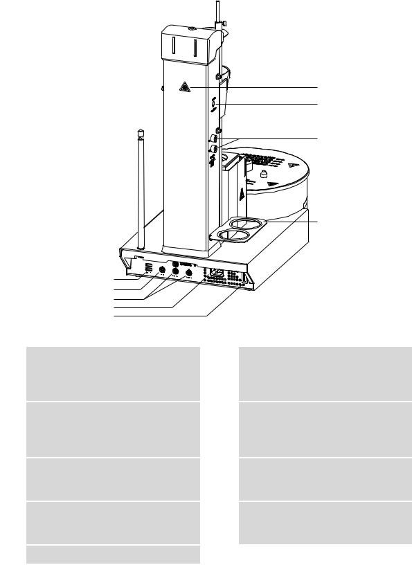
Figure 1 Front 874 Oven Sample Processor
8 |
874 Oven Sample Processor |

|
|
|
2 Overview of the instrument |
|
|
|
|
|
|
1 |
Safety shield (6.2751.140) |
|
2 |
Conditioning position |
|
|
|
|
For the conditioning vessel. |
|
|
|
|
|
|
|
|
|
|
3 |
Sample rack (6.2041.720) |
|
4 |
Turntable |
|
For 36 sample vials (6 mL). |
|
|
|
|
|
|
|
|
|
|
|
|
|
5 |
Guide bolts |
|
6 |
Guide rod |
|
For the sample rack. |
|
|
For stripping off the sample vessel. |
|
|
|
|
|
|
|
|
|
|
7 |
Rod holder |
|
8 |
Guide head |
|
With knurled screw. |
|
|
|
|
|
|
|
|
|
|
|
|
|
9 |
Working head |
|
10 |
Distributor |
|
|
|
|
|
|
|
|
|
|
11 |
Gas outlet |
|
12 |
Air pump inlet |
|
With M6 thread. |
|
|
For the 6.2724.010 |
|
|
|
|
|
|
|
|
|
|
13 |
Heating tube connector |
|
14 |
Lift |
|
|
|
|
|
|
|
|
|
|
15 |
Support rod (6.2016.030) |
|
16 |
Beaker sensor |
|
For fixing the titration cell. |
|
|
|
|
|
|
|
|
17Oven module
With PTFE covering.
18Oven housing
With ventilation slits.
874 Oven Sample Processor |
9 |
6 |
7 |
8 |
9 |
USB 2
1
2
3
4
5
Figure 2 Rear 874 Oven Sample Processor
1USB connector (USB 1 and USB 2)
USB ports (type A) for connecting a printer, USB hub, Titrandos, additional USB devices etc.
2Controller connector (Controller)
For connecting a computer with installed PC software.
3 MSB connector (MSB 1 to MSB 3) 4 Mains connection socket
Metrohm Serial Bus. For connecting external dosing devices, stirrers or remote boxes. Mini DIN, 9-pin.
5Type plate
Contains specifications concerning mains voltage, instrument type and serial number.
7Air/nitrogen connector
With M6 interior thread. Inlet for external gassing.
9Drying flask holder
6Warning symbol
Biological hazard.(see Chapter 1.3.4, page 5)
8Gas inlet and outlet
For connecting drying flasks, with M6 inner thread.
10 |
874 Oven Sample Processor |
|
2 Overview of the instrument |
1
2
3
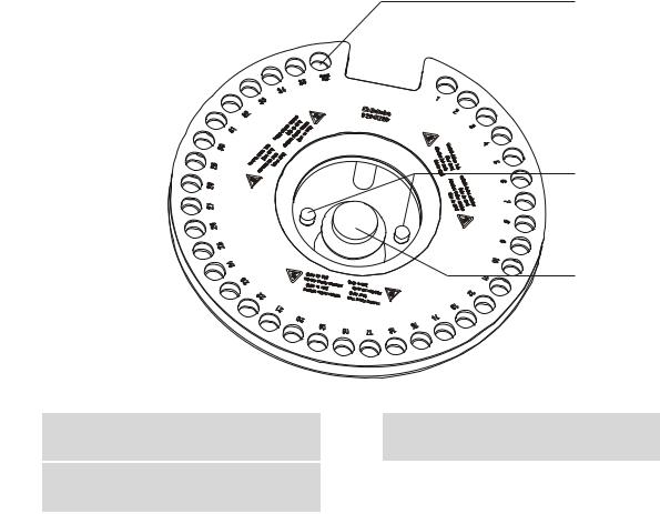
Figure 3 6.2041.720 sample rack
1 |
Conditioning position |
2 |
Guide pins |
For the conditioning vessel.
3Handle
With fixing screw.
874 Oven Sample Processor |
11 |
3.1 Setting up the instrument |
|
3Installation
3.1Setting up the instrument
3.1.1Packaging
The instrument is supplied in highly protective special packaging together with the separately packed accessories. Keep this packaging, as only this ensures safe transportation of the instrument.
3.1.2Checks
Immediately after receipt, check whether the shipment has arrived complete and without damage by comparing it with the delivery note.
3.1.3Location
The instrument has been developed for operation indoors and may not be used in explosive environments.
Place the instrument in a location of the laboratory which is suitable for operation, free of vibrations, protected from corrosive atmosphere, and contamination by chemicals.
The instrument should be protected against excessive temperature fluctuations and direct sunlight.
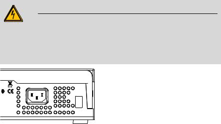
3.2Connecting a mains cable
Warning
This instrument must not be operated except with the mains voltage specified for it (see rear panel of the instrument).
Protect the connection sockets against moisture.
P: 115W |
U: 100 - 240 V |
f: 50 - 60 Hz |
|
|
Nr. |
Figure 4 Connecting the mains cable
12 |
874 Oven Sample Processor |
|
3 Installation |
3.3Mounting the sample insert
The dimensions of the supplied sample insert are optimized for the usage of 6.2419.007 sample vials (6 mL) from Metrohm . This ensures the best possible transfer of heat between oven and sample.
3
6.2063.020
6.2627.010
2


 1
1
Figure 5 Mounting the sample insert
Note
The sample insert may not be inserted or removed unless it has been cooled down.
Proceed as follows:
1Insert the 6.2627.010 oven insert with the spring in place into the oven from above and slide it all the way to the bottom.
2 Place the 6.2063.020 sample insert into the oven from above.
3Tighten the sample insert with the supplied hexagon screws. The required hexagon key is part of the accessories.
874 Oven Sample Processor |
13 |

3.4 Mounting the needles |
|
Note
If vessels with other dimensions are to be used, then individually modified sample inserts can be ordered. The precise vessel dimensions (including tolerances) will be required when ordering. Non-standard sample vessels may not exhibit dimensions outside of the following limit values:
Diameter 10.0…32.0 mm
Immersion depth 20.0…45.0 mm
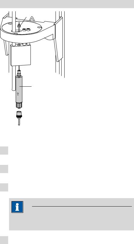
3.4Mounting the needles
Two different types of needle holders are available for mounting needles. The length of the needle holder defines how deeply the injection needle penetrates the sample vessel. The 6.2049.040 needle holder, which is 58 mm in length, ensures that the needle penetrates the liquid or powdery sample. The carrier gas can flow through the sample and effect an efficient expulsion of the moisture it contains.
If there is a danger that the heated sample could clog the needle, then use the 6.2049.050 needle holder with 73 mm length. In this case the injection needle penetrates the sample vessel only slightly deeper than the outlet needle and has no contact with the sample itself.
Needle holders with the dimensions required for situations calling for special sample vessels can be supplied by Metrohm upon request.
14 |
874 Oven Sample Processor |
|
3 Installation |
Mounting the injection and outlet needle
6.2816.070
3
6.2049.040/6.2049.050
1 


2 

 6.2816.080
Figure 6 Mounting the needles
Mount the needles as follows
1Screw the needle holder (6.2049.040 or 6.2049.050) into the distributor on the guide head.
2Screw the 6.2816.080 outlet needle onto the Luer connector of the needle holder.
3Carefully guide the 6.2816.070 injection needle into the opening of the distributor from above and allow it to drop down.
Note
Take care to ensure that the white PTFE seal is positioned securely on the needle.
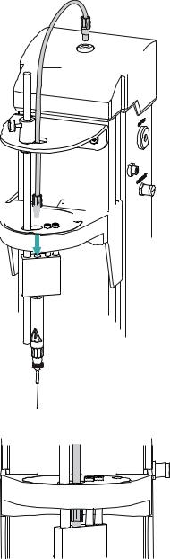
4Screw the 6.1805.470 FEP tubing by hand onto the opening of the distributor. Screw the other end of the tube into the opening of the gas outlet on the upper side of the tower.
874 Oven Sample Processor |
15 |
3.4 Mounting the needles |
|
6.1805.470 


 4
4 


Figure 7 Mounting the tubing
16 |
874 Oven Sample Processor |
Loading...