


 Loading...
899 Coulometer
Manual
8.899.8001EN

Metrohm AG CH-9100 Herisau Switzerland
Phone +41 71 353 85 85 Fax +41 71 353 89 01 info@metrohm.com www.metrohm.com
899 Coulometer
Manual
8.899.8001EN |
04.2012 ebe |
Teachware Metrohm AG CH-9100 Herisau
teachware@metrohm.com
This documentation is protected by copyright. All rights reserved.
Although all the information given in this documentation has been checked with great care, errors cannot be entirely excluded. Should you notice any mistakes please send us your comments using the address given above.
Documentation in additional languages can be found on http://products.metrohm.com under Literature/Technical documentation.
|
Table of contents |
Table of contents
1 Introduction |
1 |
|
1.1 |
Instrument description ......................................................... |
1 |
1.1.1 |
Connectors .............................................................................. |
1 |
1.1.2 |
Intended use ........................................................................... |
2 |
1.2 |
About the documentation ................................................... |
2 |
1.2.1 |
Symbols and conventions ........................................................ |
2 |
1.3 |
Safety instructions ................................................................ |
3 |
1.3.1 |
General notes on safety ........................................................... |
3 |
1.3.2 |
Electrical safety ........................................................................ |
3 |
1.3.3 |
Tubing and capillary connections ............................................. |
4 |
1.3.4 |
Flammable solvents and chemicals ........................................... |
5 |
1.3.5 |
Recycling and disposal ............................................................. |
5 |
2 Overview of the instrument |
6 |
|
2.1 |
Front ...................................................................................... |
6 |
2.2 |
Rear ........................................................................................ |
7 |
3 Installation |
|
8 |
3.1 |
Setting up the instrument .................................................... |
8 |
3.1.1 |
Packaging ................................................................................ |
8 |
3.1.2 |
Checks .................................................................................... |
8 |
3.1.3 |
Location .................................................................................. |
8 |
3.2 |
Setting up the coulometer cell ............................................ |
9 |
3.2.1 |
Inserting the coulometer cell .................................................... |
9 |
3.2.2 |
Preparing the coulometer cell .................................................. |
9 |
3.2.3 |
Mounting the addition and aspiration tube (utilization with Ti |
|
|
Stand) ................................................................................... |
13 |
3.2.4 |
Using the coulometer cell with a Karl Fischer oven ................. |
14 |
3.2.5 |
Using the coulometer cell with a sample changer .................. |
14 |
3.3 |
Connecting the coulometer to the power supply ............ |
14 |
3.3.1 |
Connecting the power supply unit ......................................... |
14 |
3.3.2 |
Connecting the Power Box .................................................... |
15 |
3.4 |
Connecting sensors ............................................................ |
17 |
3.4.1 |
Connecting a generator electrode .......................................... |
17 |
3.4.2 |
Connecting an indicator electrode ......................................... |
18 |
3.4.3 |
Connecting a temperature sensor .......................................... |
20 |
3.5 |
Connecting an additional stirrer ....................................... |
21 |
3.6 |
Connecting a balance ......................................................... |
22 |
3.7Connecting a keyboard, printer and other USB devi-
ces ........................................................................................ |
24 |
899 Coulometer |
III |
Table of contents |
|
|
|
|
3.8 |
Connecting a sample changer to the remote connec- |
|
|
|
tor ........................................................................................ |
27 |
4 |
Coulometric titration |
28 |
|
|
4.1 |
Principle of coulometry according to Karl Fischer .......... |
28 |
|
4.2 |
Working with water standards ......................................... |
29 |
|
4.2.1 |
Certified water standards ....................................................... |
29 |
|
4.2.2 |
Practical recommendations .................................................... |
29 |
|
4.3 |
Sample addition .................................................................. |
31 |
|
4.3.1 |
Size of the sample size ........................................................... |
31 |
|
4.3.2 |
Working with liquid samples .................................................. |
32 |
|
4.3.3 |
Working with solid samples ................................................... |
32 |
|
4.4 |
Optimum working conditions ........................................... |
33 |
|
4.4.1 |
General ................................................................................. |
33 |
|
4.4.2 |
Drift ...................................................................................... |
33 |
|
4.4.3 |
Reagent replacement ............................................................. |
34 |
|
4.4.4 |
Indicator electrode ................................................................ |
34 |
5 |
Operation |
|
35 |
|
5.1 |
Switching the instrument on and off ............................... |
35 |
|
5.2 |
Fundamentals of operation ............................................... |
36 |
|
5.2.1 |
The keypad ............................................................................ |
36 |
|
5.2.2 |
Structure of the dialog windows ............................................ |
36 |
|
5.2.3 |
Navigating in the dialog ......................................................... |
37 |
|
5.2.4 |
Entering text and numbers ..................................................... |
37 |
|
5.2.5 |
Selecting from a selection list ................................................. |
38 |
|
5.3 |
Formula editor .................................................................... |
39 |
|
5.4 |
Methods .............................................................................. |
40 |
|
5.4.1 |
Method templates ................................................................. |
40 |
|
5.4.2 |
Loading a method template ................................................... |
40 |
|
5.4.3 |
Saving a method ................................................................... |
41 |
|
5.4.4 |
Exporting a method ............................................................... |
42 |
|
5.5 |
Control ................................................................................. |
43 |
|
5.6 |
Sample data ........................................................................ |
44 |
|
5.6.1 |
Entering sample data in the main dialog ................................ |
44 |
|
5.6.2 |
Requesting sample data at the start of the determination ...... |
45 |
|
5.7 |
Sample table ....................................................................... |
45 |
|
5.7.1 |
General ................................................................................. |
45 |
|
5.7.2 |
Editing the sample data ......................................................... |
47 |
|
5.7.3 |
Sending the sample size from a balance ................................. |
49 |
|
5.8 |
Carrying out a determination ............................................ |
49 |
|
5.9 |
Live modifications .............................................................. |
52 |
|
5.9.1 |
Editing the sample data of the running determination ............ |
52 |
|
5.9.2 |
Editing the sample table while a determination is running ...... |
53 |
IV |
899 Coulometer |
|
|
Table of contents |
||
|
5.9.3 |
Editing the live parameters ..................................................... |
|
55 |
|
5.10 |
Results ................................................................................. |
|
56 |
|
5.11 |
Statistics .............................................................................. |
|
57 |
|
5.12 Printing a report manually ................................................. |
|
59 |
|
|
5.13 |
Manual control ................................................................... |
|
60 |
|
5.13.1 |
Stirring .................................................................................. |
|
60 |
6 |
System settings |
|
62 |
|
|
6.1 |
Basic settings ...................................................................... |
|
62 |
|
6.2 |
Managing common variables ............................................ |
|
65 |
|
6.2.1 |
General ................................................................................. |
|
65 |
|
6.2.2 |
Editing common variables ...................................................... |
|
65 |
|
6.3 |
File management ................................................................ |
|
66 |
|
6.4 |
Configuring external devices ............................................. |
|
68 |
|
6.5 |
Instrument diagnosis .......................................................... |
|
71 |
|
6.5.1 |
Loading program versions and language files ......................... |
|
71 |
|
6.5.2 |
Diagnosis functions ............................................................... |
|
72 |
7 |
Parameters |
|
|
73 |
|
7.1 |
Coulometric Karl Fischer titrations (KFC) ......................... |
|
73 |
|
7.1.1 |
Conditioning ......................................................................... |
|
73 |
|
7.1.2 |
Start conditions ..................................................................... |
|
75 |
|
7.1.3 |
Control parameters ................................................................ |
|
76 |
|
7.1.4 |
Titration parameters .............................................................. |
|
79 |
|
7.1.5 |
Stop conditions ..................................................................... |
|
81 |
|
7.1.6 |
Calculation ............................................................................ |
|
81 |
|
7.1.7 |
Statistics ................................................................................ |
|
85 |
|
7.1.8 |
Reports .................................................................................. |
|
86 |
8 |
Operation and maintenance |
|
88 |
|
|
8.1 |
Quality Management and validation with Metrohm ....... |
88 |
|
9 |
Troubleshooting |
|
89 |
|
|
9.1 |
Karl Fischer titration .......................................................... |
|
89 |
|
9.2 |
Miscellaneous ..................................................................... |
|
91 |
10 Appendix |
|
|
92 |
|
|
10.1 |
Stirring rate ......................................................................... |
|
92 |
|
10.2 |
Balance ................................................................................ |
|
92 |
|
10.3 |
USB devices ......................................................................... |
|
93 |
|
10.3.1 |
6.2147.000 numerical USB keypad ........................................ |
|
93 |
|
10.3.2 |
Key assignment of a USB keyboard ........................................ |
|
94 |
|
10.3.3 |
PC mouse .............................................................................. |
|
95 |
899 Coulometer |
V |
Table of contents |
|
|
10.3.4 |
Printer ................................................................................... |
95 |
10.4 |
Control parameters and polarization current .................. |
95 |
10.5 |
Method examples for working with the Karl Fischer |
|
|
oven ..................................................................................... |
97 |
10.6 |
System initialization ........................................................... |
98 |
10.7 |
Remote interface ................................................................ |
99 |
10.7.1 Pin assignment of the remote interface .................................. |
99 |
|
10.7.2 Status diagram of the remote interface ................................ |
100 |
|
10.8 |
Remote control via an RS-232 connection ..................... |
101 |
10.8.1 |
Commands and variables ..................................................... |
102 |
10.9 |
Arithmetic algorithms in the 899 Coulometer ............... |
103 |
11 Technical specifications |
106 |
|
11.1 |
Measuring inputs .............................................................. |
106 |
11.1.1 |
Indicator electrode .............................................................. |
106 |
11.1.2 |
Temperature ........................................................................ |
106 |
11.2 |
Generator connector ........................................................ |
106 |
11.2.1 |
Generator electrode ............................................................ |
106 |
11.3 |
Internal stirrer ................................................................... |
107 |
11.4 |
Interfaces and connectors ............................................... |
107 |
11.5 |
Power supply .................................................................... |
107 |
11.6 |
Safety specifications ........................................................ |
108 |
11.7 |
Electromagnetic compatibility (EMC) ............................. |
108 |
11.8 |
Ambient temperature ...................................................... |
109 |
11.9 |
Reference conditions ........................................................ |
109 |
11.10 |
Dimensions ........................................................................ |
109 |
12 Warranty (Guarantee) |
110 |
|
13 Accessories |
|
112 |
13.1 |
Scope of delivery .............................................................. |
112 |
13.1.1 |
2.899.0010 ......................................................................... |
112 |
13.1.2 |
2.899.0110 ......................................................................... |
119 |
13.1.3 |
2.899.1010 ......................................................................... |
125 |
13.1.4 |
2.899.1110 ......................................................................... |
132 |
13.1.5 |
2.899.2110 ......................................................................... |
139 |
13.1.6 |
2.899.3110 ......................................................................... |
152 |
13.2 |
Optional accessories ........................................................ |
164 |
Index |
|
167 |
VI |
899 Coulometer |
|
Table of figures |
Table of figures |
|
|
Figure 1 |
Front 899 Coulometer ....................................................................... |
6 |
Figure 2 |
Rear 899 Coulometer ........................................................................ |
7 |
Figure 3 |
Inserting the coulometer cell ............................................................. |
9 |
Figure 4 |
Filling the adsorber tube .................................................................. |
10 |
Figure 5 |
Equipping the coulometer cell ......................................................... |
11 |
Figure 6 |
Mounting the addition and aspiration tube ...................................... |
13 |
Figure 7 |
Connecting the power supply unit ................................................... |
15 |
Figure 8 |
Connecting the Power Box .............................................................. |
16 |
Figure 9 |
Unscrewing the cover from the generator electrode ........................ |
17 |
Figure 10 |
Screwing the electrode cable to the general electrode ..................... |
18 |
Figure 11 |
Connecting a generator electrode ................................................... |
18 |
Figure 12 |
Unscrew the cover from the indicator electrode .............................. |
19 |
Figure 13 |
Screwing on the electrode cable to the indicator electrode .............. |
19 |
Figure 14 |
Connecting an indicator electrode ................................................... |
19 |
Figure 15 |
Connecting a temperature sensor .................................................... |
20 |
Figure 16 |
Connecting a stirrer ......................................................................... |
21 |
Figure 17 |
Connecting the balance via RS-232/USB Box .................................... |
22 |
Figure 18 |
Connecting USB devices .................................................................. |
24 |
Figure 19 |
Connecting the USB flash drive ........................................................ |
26 |
Figure 20 |
Connecting the 6.2147.000 USB keyboard with USB flash drive and |
|
|
printer ............................................................................................. |
26 |
Figure 21 |
Connecting the USB hub with USB flash drive, printer and 6.2148.030 |
|
|
RS-232/USB Box .............................................................................. |
27 |
Figure 22 |
Connecting a remote cable ............................................................. |
27 |
Figure 23 |
Keypad 899 Coulometer .................................................................. |
36 |
Figure 24 |
Directory structure on the USB flash drive ........................................ |
67 |
Figure 25 |
Rotational speed depending on stirring rate .................................... |
92 |
Figure 26 |
Control parameters and polarization current .................................... |
96 |
Figure 27 |
Pin assignment of remote socket and remote plug .......................... |
99 |
Figure 28 |
Remote status diagram .................................................................. |
100 |
Figure 29 |
Connecting the RS-232/USB Box to the PC .................................... |
101 |
899 Coulometer |
VII |
|
1 Introduction |
1 Introduction
1.1Instrument description
The 899 Coulometer is a titrator used for coulometric water content determination according to Karl Fischer. There are method templates available which are already configured except for a few parameters. The methods can be modified and stored under a new name. The methods can be exported to a connected USB flash drive. This function makes it possible for you to copy methods quickly and easily from one instrument to another.
The 899 Coulometer has an integrated magnetic stirrer that is visible on the top side of the housing. The coulometer cell can easily be attached to the magnetic stirrer. Thanks to its compact construction, you can use the device in a small space as a stand-alone titrator. Furthermore, the remote interface permits you to connect a sample changer with oven module and to perform automated determinations.
As an alternative to the power supply with the power supply unit provided, the 899 Coulometer can also be operated by means of an accumulator (a so-called Power Box). The Power Box is available as optional equipment. It is particularly appropriate for use in environments where power supplies are either unstable or absent.
1.1.1Connectors
The instrument is equipped with the following connectors:
Electrical connection
For connecting to the mains supply with the aid of the power supply unit provided or for connection to the 6.2164.500 Power Box.
MSB connector (Metrohm Serial Bus)
For connecting an additional stirrer.
USB (OTG) connector
The 6.2151.100 adapter can be used to connect, for example, a printer, a USB flash drive or a USB keyboard.
Sensor connectors
Three connectors for the following sensor types:
–Double Pt electrode
–Generator electrode
–Temperature sensor (Pt1000)
Grounding socket
For grounding the Coulometer.
899 Coulometer |
1 |
1.2 About the documentation |
|
Remote connector
For connecting instruments with a remote interface (e.g. 885 Compact Oven SC).
1.1.2Intended use
The 899 Coulometer is designed for usage as a titrator in analytical laboratories. Its application field is coulometric water content determination according to Karl Fischer.
This instrument is suitable for processing chemicals and flammable samples. The usage of the 899 Coulometer therefore requires that the user have basic knowledge and experience in the handling of toxic and caustic substances. Knowledge with respect to the application of the fire prevention measures prescribed for laboratories is also mandatory.
1.2About the documentation
Caution
Please read through this documentation carefully before putting the instrument into operation. The documentation contains information and warnings which the user must follow in order to ensure safe operation of the instrument.
1.2.1Symbols and conventions
The following symbols and formatting may appear in this documentation:
|
Cross-reference to figure legend |
|
The first number refers to the figure number, the sec- |
|
ond to the instrument part in the figure. |
|
|
|
Instruction step |
|
Carry out these steps in the sequence shown. |
|
|
Method |
Dialog text, parameter in the software |
|
|
File New |
Menu or menu item |
|
|
[Next] |
Button or key |
|
|
|
Warning |
|
This symbol draws attention to a possible life hazard |
|
or risk of injury. |
|
|
2 |
899 Coulometer |
|
1 Introduction |
Warning
This symbol draws attention to a possible hazard due to electrical current.
Warning
This symbol draws attention to a possible hazard due to heat or hot instrument parts.
Warning
This symbol draws attention to a possible biological hazard.
Caution
This symbol draws attention to a possible damage of instruments or instrument parts.
Note
This symbol marks additional information and tips.
1.3Safety instructions
1.3.1General notes on safety
Warning
This instrument may only be operated in accordance with the specifications in this documentation.
This instrument has left the factory in a flawless state in terms of technical safety. To maintain this state and ensure non-hazardous operation of the instrument, the following instructions must be observed carefully.
1.3.2Electrical safety
The electrical safety when working with the instrument is ensured as part of the international standard IEC 61010.
Warning
Only personnel qualified by Metrohm are authorized to carry out service work on electronic components.
899 Coulometer |
3 |
1.3 Safety instructions |
|
Warning
Never open the housing of the instrument. The instrument could be damaged by this. There is also a risk of serious injury if live components are touched.
There are no parts inside the housing which can be serviced or replaced by the user.
Mains voltage
Warning
An incorrect mains voltage can damage the instrument.
Only operate this instrument with a mains voltage specified for it (see rear panel of the instrument).
Protection against electrostatic charges
Warning
Electronic components are sensitive to electrostatic charges and can be destroyed by discharges.
Do not fail to pull the mains cable out of the mains connection socket before you set up or disconnect electrical plug connections at the rear of the instrument.
1.3.3Tubing and capillary connections
Caution
Leaks in tubing and capillary connections are a safety risk. Tighten all connections well by hand. Avoid applying excessive force to tubing connections. Damaged tubing ends lead to leakage. Appropriate tools can be used to loosen connections.
Check the connections regularly for leakage. If the instrument is used mainly in unattended operation, then weekly inspections are mandatory.
4 |
899 Coulometer |
|
1 Introduction |
1.3.4Flammable solvents and chemicals
Warning
All relevant safety measures are to be observed when working with flammable solvents and chemicals.
Set up the instrument in a well-ventilated location (e.g. laboratory flue).
Keep all sources of flame far from the workplace.
Clean up spilled fluids and solids immediately.
Follow the safety instructions of the chemical manufacturer.
1.3.5Recycling and disposal
This product is covered by European Directive 2002/96/EC, WEEE – Waste from Electrical and Electronic Equipment.
The correct disposal of your old equipment will help to prevent negative effects on the environment and public health.
More details about the disposal of your old equipment can be obtained from your local authorities, from waste disposal companies or from your local dealer.
899 Coulometer |
5 |
2.1 Front |
|
2 Overview of the instrument
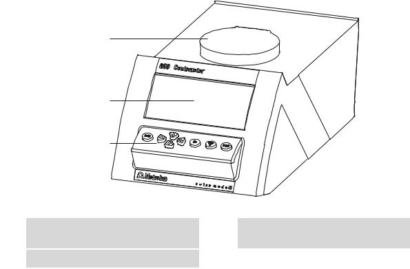
2.1Front
1
2
3
Figure 1 Front 899 Coulometer
1 |
Magnetic stirrer |
2 |
Display |
For attaching the titration vessel holder.
3Keypad
6 |
899 Coulometer |
|
2 Overview of the instrument |
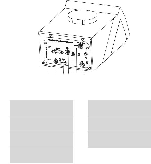
2.2Rear
|
|
|
|
|
|
|
|
|
|
|
|
|
|
|
|
|
|
|
|
|
|
|
|
|
|
|
|
|
|
|
|
|
|
|
|
|
|
|
|
|
|
|
|
|
|
|
|
|
|
|
|
|
|
|
|
|
|
|
|
|
|
|
|
|
|
|
3 |
|
5 |
6 7 |
8 9 |
|||
|
|
|
|
|
|
|
|
|||||||
1 |
|
|
|
4 |
||||||||||
2 |
||||||||||||||
Figure 2 Rear 899 Coulometer |
||||||||||||||
|
|
|
|
|
|
|
|
|
|
|
|
|
|
|
1 Type plate |
|
|
|
|
|
|
|
|
|
2 Remote connector |
||||
Contains the serial number. |
|
|
|
|
|
|
|
|
|
|
For connecting instruments with a remote |
|||
|
|
|
|
|
|
|
|
|
|
|
|
|
|
interface. D-Sub, 9-pin. |
|
|
|
|
|
|
|
|
|
|
|
|
|
|
|
3Electrode connector (Ind.)
For connecting a metal electrode (double Pt wire electrode). Socket F.
5MSB connector (MSB 1)
Metrohm Serial Bus. For connecting an external stirrer. Mini DIN, 8-pin.
7Mains connection socket (Power)
For connecting the external power supply unit or a Power Box (6.2164.500).
9Grounding socket
For grounding the Coulometer. Socket B, 4 mm.
4Temperature sensor connector (Temp.)
For connecting a temperature sensor of the type Pt1000. Two B sockets, 2 mm.
6USB (OTG) connector
For connecting printers, USB flash drives, USB hubs, etc.
8Electrode connector (Gen.)
For connecting a generator electrode.
899 Coulometer |
7 |
3.1 Setting up the instrument |
|
3 Installation
3.1Setting up the instrument
3.1.1Packaging
The instrument is supplied in highly protective special packaging together with the separately packed accessories. Keep this packaging, as only this ensures safe transportation of the instrument.
3.1.2Checks
Immediately after receipt, check whether the shipment has arrived complete and without damage by comparing it with the delivery note.
3.1.3Location
The instrument has been developed for operation indoors and may not be used in explosive environments.
Place the instrument in a location of the laboratory which is suitable for operation, free of vibrations, protected from corrosive atmosphere, and contamination by chemicals.
The instrument should be protected against excessive temperature fluctuations and direct sunlight.
8 |
899 Coulometer |
|
3 Installation |
3.2Setting up the coulometer cell
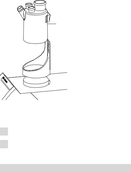
3.2.1Inserting the coulometer cell
6.1464.320
 2
2

 6.2047.030


 1
1
Figure 3 Inserting the coulometer cell
Set up the coulometer cell on the magnetic stirrer as follows:
1 Attach the 6.2047.030 titration vessel holder to the magnetic stirrer.
2Insert the 6.1464.320 coulometer cell into the titration vessel holder.
3.2.2Preparing the coulometer cell
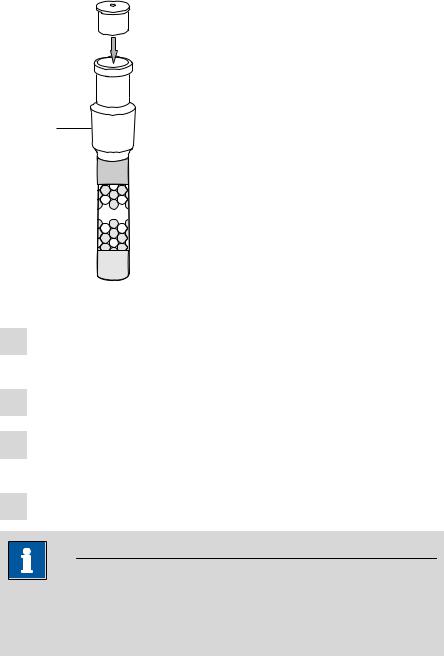
Filling the adsorber tube
Before setting up the coulometer cell the 6.1403.030 adsorber tube has to be filled with 6.2811.000 molecular sieve. Proceed as follows:
899 Coulometer |
9 |
3.2 Setting up the coulometer cell |
|
4
6.1403.030
3
6.2811.000 
 2
2
1
Figure 4 Filling the adsorber tube
1Insert a small cotton plug into the bottom of the adsorber tube. Do not pack the cotton too tightly.
2 Fill the molecular sieve up to the ¾ level.
3Place a small cotton plug on the molecular sieve. Do not pack the cotton too tightly.
4 Seal the adsorber tube with the appropriate cover.
Note
Note that the molecular sieve must be replaced at regular intervals. Each time you refill the adsorber tube with molecular sieve, you can, for example, write the date directly on the adsorber tube.
10 |
899 Coulometer |
|
3 Installation |
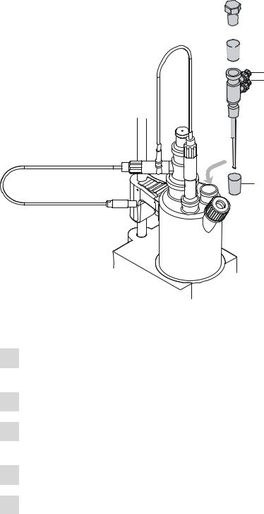
Equipping the coulometer cell
3
6.1403.030

 2
2
6.2713.020
5
6.0341.100 4 6.0345.100 6.0344.100
6.2713.000 |
|
|
6.1437.000 |
|
|
|
|
6.2701.040 |
2 |
2 |
6.2713.010 |
|
|
|
|
6.1448.020 |
6 |
|
|
|
|
|
6.1464.320
1
 6.1903.030
Figure 5 Equipping the coulometer cell
Equip the coulometer cell as follows:
1 Place the 6.1903.030 stirring bar in the coulometer cell.
2Cut the 6.2713.0x0 ground-joint sleeves to the correct length and attach them to the ground joints of the inserts (electrodes, adsorber tube, etc.).
Take care to ensure that the edges of the ground-joint sleeves are cut to size cleanly and that there are no fringes. The ground-joint sleeves are not permitted to protrude at the lower edge of the ground-joint opening.
3 Insert the 6.1403.030 adsorber tube into the generator electrode.
899 Coulometer |
11 |

3.2 Setting up the coulometer cell |
|
4Insert the 6.0345.100 generator electrode without diaphragm or the 6.0344.100 generator electrode with diaphragm together with the adsorber tube into the large ground-joint opening at the rear.
5Insert the 6.0341.100 indicator electrode into the left ground-joint opening.
6Place the 6.1448.020 septum on the front opening of the coulometer cell and screw it shut with the 6.2701.040 screw cap.
Tighten the screw cap only enough so that it seals. The septum is not permitted to bend.
Filling the coulometer cell (generator electrode with diaphragm)
Proceed as follows when using a generator electrode with a diaphragm:
1 Fill approximately 5 mL of catholyte into the generator electrode.
2Fill approximately 100 mL of anolyte into the coulometer cell with the aid of the 6.2738.000 funnel. The level of the anolyte should be roughly 1-2 mm above the level of the catholyte.
3Close the remaining ground-joint opening on the right with the 6.1437.000 ground-joint stopper (with ground-joint sleeve attached).
Filling the coulometer cell (generator electrode without diaphragm)
Proceed as follows when using a generator electrode without a diaphragm:
1Fill approximately 100 mL of reagent into the coulometer cell with the aid of the 6.2738.000 funnel.
2Close the remaining ground-joint opening on the right with the 6.1437.000 ground-joint stopper (with ground-joint sleeve attached).
12 |
899 Coulometer |
|
3 Installation |
3.2.3Mounting the addition and aspiration tube (utilization with Ti Stand)
 6.1437.000
2
1


 6.2713.000
5
6


 6.1439.010
4
6.2713.000
3
Figure 6 Mounting the addition and aspiration tube
Insert the addition and aspiration tube as follows into the coulometer cell:
1Attach the 6.2713.000 ground-joint sleeve that has been cut to size to the ground joint of the 6.1437.000 stopper.
2 Insert the stopper into the 6.1439.010 addition and aspiration tube.
3Attach the 6.2713.000 ground-joint sleeve that has been cut to size to the ground joint of the addition and aspiration tube.
4 Insert everything together into the ground-joint opening.
5Connect the tubing for the reagent addition at the upper connector of the addition and aspiration tube (5).
899 Coulometer |
13 |

3.3 Connecting the coulometer to the power supply |
|
6Connect the tubing for the aspiration of the coulometer cell at the lower connector of the addition and aspiration tube (6).
Details regarding how to connect the addition tubing and the aspiration tubing can be found in the manual for the 803 Ti Stand.
3.2.4Using the coulometer cell with a Karl Fischer oven
When samples release their water only slowly or only at higher temperatures, the oven method is used. The sample is heated in a KF oven (e.g. 860 KF Thermoprep) and the water that is released is guided with a carrier gas into the coulometer cell. You will find recommended parameter settings for determinations with a Karl Fischer oven in chapter 10.5, page 97.
A detailed description of setting up the coulometer cell with the KF oven can be found in the respective manual.
3.2.5Using the coulometer cell with a sample changer
When there is a large number of samples, the determination of the water content can be automated with the aid of a sample changer with oven module (e.g. 885 Compact Oven SC). You will find recommended parameter settings for determinations with a Karl Fischer oven in chapter 10.5, page 97.
A detailed description of setting up the coulometer cell with the sample changer can be found in the respective manual.
3.3Connecting the coulometer to the power supply
You can supply the 899 Coulometer with electricity two different ways:
Connect the coulometer directly to the mains supply with the aid of the power supply unit provided.
Connect the coulometer to the 6.2164.500 Power Box if no stable mains supply is available.
3.3.1Connecting the power supply unit
The 899 Coulometer has an external power supply unit for a 24 V power supply (DC). This is connected to the mains connection of the Coulometer.
Warning
An incorrect mains voltage can damage the instrument.
Operate the instrument only with the mains voltage specified for it. Use the supplied power supply unit exclusively.
14 |
899 Coulometer |
|
3 Installation |
Figure 7 Connecting the power supply unit
Proceed as follows:
1Connect the plug of the external power supply unit with the mains connection (2-7) of the Coulometer.
Note
The plug of the power supply unit is protected against accidental disconnection of the cable by means of a pull-out protection feature. If you wish to pull out the plug, you will first need to pull back the outer plug sleeve.
2Connect the mains cable with the external power supply unit of the Coulometer and with the mains supply.
Caution
Switch off the Coulometer correctly by pressing the red [STOP] key before you interrupt the electricity supply. If this is not done, then there is a danger of data loss.
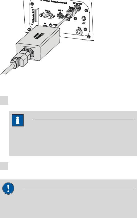
3.3.2Connecting the Power Box
As an alternative to the power supply from the mains supply, the option exists of providing the 899 Coulometer with electricity through the 6.2164.500 Power Box. This means that you can also use the instrument in environments in which no stable mains supply is available. Details regarding the Power Box can be found in the respective manual.
899 Coulometer |
15 |

3.3 Connecting the coulometer to the power supply |
|
Figure 8 Connecting the Power Box
Proceed as follows:
1Connect the plug of the Power Box with the mains connection (2-7) of the Coulometer.
Note
The Power Box plug is protected against accidental disconnection of the cable by means of a "pull-out protection" feature. If you wish to pull out the plug, you will first need to pull back the outer plug sleeve.
Caution
Switch off the Coulometer correctly by pressing the red [STOP] key before you interrupt the connection with the Power Box. If this is not done, then there is a danger of data loss.
16 |
899 Coulometer |
|
3 Installation |
3.4Connecting sensors
The measuring interface contains the following measuring inputs:
Gen. for a generator electrode
Ind. for a double Pt electrode
Temp. for a temperature sensor of the Pt1000 type
Caution
Under all circumstances, avoid mixing up the electrode cable from the indicator electrode with the one from the generator electrode. Attach corresponding markings on the screw heads of the cables.
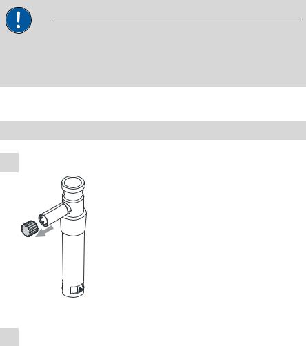
3.4.1Connecting a generator electrode
Screwing the electrode cable to the general electrode
1 Unscrew the cover of the generator electrode.
1
Figure 9 Unscrewing the cover from the generator electrode
2Screw the 6.2104.120 electrode cable tightly onto the generator electrode.
899 Coulometer |
17 |
3.4 Connecting sensors |
|
6.2104.120
2
Figure 10 Screwing the electrode cable to the general electrode
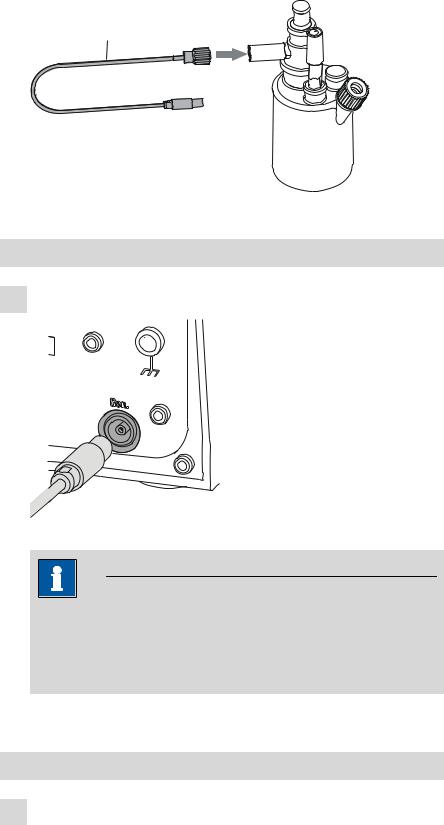
Connecting the electrode cable to the coulometer
1 Plug the electrode plug into the Gen. socket of the Coulometer.
Figure 11 Connecting a generator electrode
Note
The electrode cable is protected against accidental disconnection of the cable by means of a pull-out protection. If you wish to pull out the plug again, you will first need to pull back the outer plug sleeve.
3.4.2Connecting an indicator electrode
Screwing on the electrode cable to the indicator electrode
1 Unscrew the cover of the indicator electrode.
18 |
899 Coulometer |

|
3 Installation |
1
Figure 12 Unscrew the cover from the indicator electrode
2Screw the 6.2104.020 electrode cable tightly onto the indicator electrode.
6.2104.020

 2
2
Figure 13 Screwing on the electrode cable to the indicator electrode
Connecting the electrode cable to the coulometer
1 Plug the electrode plug into the Ind. socket of the Coulometer.
Figure 14 Connecting an indicator electrode
899 Coulometer |
19 |
3.4 Connecting sensors |
|
Note
The electrode cable is protected against accidental disconnection of the cable by means of a pull-out protection. If you wish to pull out the plug again, you will first need to pull back the outer plug sleeve.
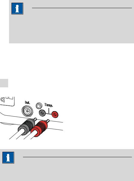
3.4.3Connecting a temperature sensor
A temperature sensor of the Pt1000 type can be connected to the Temp. connector.
Connect the temperature sensor as follows:
1Insert the plugs of the temperature sensor into the Temp. sockets of the Coulometer.
Figure 15 Connecting a temperature sensor
Note
Always insert the red plug into the red socket. It is only this way that the shielding against electrical interferences is ensured.
20 |
899 Coulometer |
Loading...