


 Loading...
865 Dosimat plus
Manual
8.865.8005EN

Metrohm AG CH-9100 Herisau Switzerland
Phone +41 71 353 85 85 Fax +41 71 353 89 01 info@metrohm.com www.metrohm.com
865 Dosimat plus
Manual
8.865.8005EN |
09.2011 dm |
Teachware Metrohm AG CH-9100 Herisau
teachware@metrohm.com
This documentation is protected by copyright. All rights reserved.
Although all the information given in this documentation has been checked with great care, errors cannot be entirely excluded. Should you notice any mistakes please send us your comments using the address given above.
Documentation in additional languages can be found on http://products.metrohm.com under Literature/Technical documentation.
|
Table of contents |
Table of contents
1 Introduction |
1 |
|
1.1 |
Instrument description ......................................................... |
1 |
1.1.1 |
Dosing modes ......................................................................... |
1 |
1.1.2 |
Connectors .............................................................................. |
1 |
1.2 |
Intended use ......................................................................... |
2 |
1.3 |
About the documentation ................................................... |
2 |
1.3.1 |
Symbols and conventions ........................................................ |
2 |
1.4 |
Safety instructions ................................................................ |
3 |
1.4.1 |
General notes on safety ........................................................... |
3 |
1.4.2 |
Electrical safety ........................................................................ |
3 |
1.4.3 |
Tubing connections ................................................................. |
4 |
1.4.4 |
Flammable solvents and chemicals ........................................... |
5 |
1.5 |
Recycling and disposal ......................................................... |
5 |
2 Overview of the instrument |
6 |
||
|
2.1 |
865 Dosimat plus ................................................................. |
6 |
|
2.2 |
Manual Dosing Controller .................................................... |
8 |
3 |
Installation |
|
9 |
|
3.1 |
Setting up the instrument .................................................... |
9 |
|
3.1.1 |
Packaging ................................................................................ |
9 |
|
3.1.2 |
Checks .................................................................................... |
9 |
|
3.1.3 |
Location .................................................................................. |
9 |
|
3.2 |
Connecting a stirrer .............................................................. |
9 |
|
3.3 |
Connecting the Manual Dosing Controller ....................... |
10 |
|
3.4 |
Connecting a balance ......................................................... |
10 |
|
3.5 |
Connecting a keyboard, printer and other USB devi- |
|
|
|
ces ........................................................................................ |
11 |
|
3.6 |
Connecting instruments to the remote connector .......... |
13 |
|
3.7 |
Connecting the 805 Dosimat ............................................. |
14 |
|
3.8 |
Attaching the exchange unit ............................................. |
15 |
4 |
Operation |
|
16 |
|
4.1 |
Switching the instrument on and off ............................... |
16 |
|
4.2 |
Fundamentals of operation ............................................... |
17 |
|
4.2.1 |
The keypad ............................................................................ |
17 |
|
4.2.2 Structure of the dialog windows ............................................ |
18 |
|
|
4.2.3 Navigating in the dialog ......................................................... |
18 |
|
865 Dosimat plus |
III |
Table of contents |
|
|
|
4.2.4 |
Entering text and numbers ..................................................... |
|
19 |
4.2.5 |
Selecting from a selection list ................................................. |
|
20 |
4.3 |
Methods .............................................................................. |
|
20 |
4.3.1 |
Method templates ................................................................. |
|
20 |
4.3.2 |
Creating a new method ......................................................... |
|
21 |
4.3.3 |
Saving a method ................................................................... |
|
21 |
4.3.4 |
Loading a method ................................................................. |
|
22 |
4.3.5 |
Exporting a method ............................................................... |
|
23 |
4.4 |
Stirrer operation ................................................................. |
|
24 |
4.5 |
Entering sample data ......................................................... |
|
25 |
4.6 |
Preparing the buret unit (PREP) ........................................ |
|
25 |
4.7 |
Printing a report manually ................................................. |
|
26 |
5 System settings |
|
28 |
|
5.1 |
Basic settings ...................................................................... |
|
28 |
5.2 |
Managing solutions ............................................................ |
|
31 |
5.2.1 |
General ................................................................................. |
|
31 |
5.2.2 |
Editing the solution data ........................................................ |
|
31 |
5.3 |
File management ................................................................ |
|
33 |
5.4 |
Configuring external devices ............................................. |
|
34 |
5.5 |
Instrument diagnosis .......................................................... |
|
37 |
5.5.1 |
Loading program versions and language files |
......................... 37 |
|
5.5.2 |
Diagnosis functions ............................................................... |
|
38 |
6 Parameters and dosing modes |
|
39 |
|
6.1 |
Manual dosing (DOS) ......................................................... |
|
39 |
6.1.1 |
General description ................................................................ |
|
39 |
6.1.2 |
Selecting a solution ............................................................... |
|
40 |
6.1.3 |
Dosing parameters ................................................................ |
|
40 |
6.1.4 |
Calculation ............................................................................ |
|
41 |
6.1.5 |
Reports .................................................................................. |
|
43 |
6.1.6 |
Pulse control .......................................................................... |
|
43 |
6.2 |
Extended dosing (XDOS) .................................................... |
|
44 |
6.2.1 |
General description ................................................................ |
|
44 |
6.2.2 |
Selecting a solution ............................................................... |
|
45 |
6.2.3 |
Selecting the operating mode ................................................ |
|
45 |
6.2.4 |
Dosing parameters ................................................................ |
|
47 |
6.2.5 |
Reports .................................................................................. |
|
48 |
6.3 |
Creating solutions (CNT D) ................................................ |
|
49 |
6.3.1 |
General description ................................................................ |
|
49 |
6.3.2 |
Selecting a solution ............................................................... |
|
51 |
6.3.3 |
Definition of the target solution ............................................. |
|
51 |
6.3.4 |
Dosing parameters ................................................................ |
|
52 |
6.3.5 |
Reports .................................................................................. |
|
53 |
IV |
865 Dosimat plus |
|
|
Table of contents |
||
|
6.4 |
Pipetting and diluting (LQT) .............................................. |
|
54 |
|
6.4.1 |
General description ................................................................ |
|
54 |
|
6.4.2 |
Selecting a solution ............................................................... |
|
56 |
|
6.4.3 Definitions of the sample transfer .......................................... |
|
56 |
|
|
6.4.4 |
Dosing parameters ................................................................ |
|
57 |
|
6.4.5 |
Reports .................................................................................. |
|
57 |
7 |
Handling and maintenance |
|
59 |
|
|
7.1 |
General ................................................................................ |
|
59 |
|
7.2 |
Quality Management and validation with Metrohm ....... |
59 |
|
8 |
Appendix |
|
|
61 |
|
8.1 |
Exchange unit ..................................................................... |
|
61 |
|
8.1.1 Maximum dosing and filling rate ............................................ |
|
61 |
|
|
8.1.2 Parameters for the preparing (PREP) ....................................... |
|
61 |
|
|
8.2 |
Stirring rate ......................................................................... |
|
62 |
|
8.3 |
Balance ................................................................................ |
|
62 |
|
8.4 |
USB devices ......................................................................... |
|
63 |
|
8.4.1 Numerical USB keypad 6.2147.000 ........................................ |
|
63 |
|
|
8.4.2 Key assignment of a USB keyboard ........................................ |
|
64 |
|
|
8.4.3 |
Printer ................................................................................... |
|
64 |
|
8.5 |
System initialization ........................................................... |
|
65 |
|
8.6 |
Remote interface ................................................................ |
|
66 |
|
8.6.1 Pin assignment of the remote interface .................................. |
|
66 |
|
|
8.6.2 Status diagram of the remote interface .................................. |
|
67 |
|
|
8.7 |
Pulse control ....................................................................... |
|
69 |
|
8.8 |
Remote control via an RS-232 connection ....................... |
|
70 |
|
8.8.1 |
Commands and variables ....................................................... |
|
71 |
9 |
Technical specifications |
|
74 |
|
|
9.1 |
Dosing drive ........................................................................ |
|
74 |
|
9.2 |
Interfaces ............................................................................. |
|
74 |
|
9.3 |
Mains connection ............................................................... |
|
74 |
|
9.4 |
Safety specification ............................................................ |
|
75 |
|
9.5 |
Electromagnetic compatibility (EMC) ................................ |
|
75 |
|
9.6 |
Ambient temperature ......................................................... |
|
75 |
|
9.7 |
Reference conditions .......................................................... |
|
76 |
|
9.8 |
Dimensions .......................................................................... |
|
76 |
10 Conformity and warranty |
|
77 |
||
|
10.1 |
Declaration of Conformity ................................................. |
|
77 |
865 Dosimat plus |
V |
Table of contents |
|
|
10.2 |
Quality Management Principles ........................................ |
78 |
10.3 |
Warranty (guarantee) ......................................................... |
79 |
11 Accessories |
|
80 |
11.1 |
Scope of delivery 865 Dosimat plus 2.865.0010 ............. |
80 |
11.2 |
Optional accessories ........................................................... |
82 |
Index |
|
86 |
VI |
865 Dosimat plus |
|
Table of figures |
Table of figures |
|
|
Figure 1 |
Front 865 Dosimat plus ..................................................................... |
6 |
Figure 2 |
Rear 865 Dosimat plus ...................................................................... |
7 |
Figure 3 |
Manual Dosing Controller 6.2107.100 ............................................... |
8 |
Figure 4 |
Connecting a stirrer ........................................................................... |
9 |
Figure 5 |
Connecting the Manual Dosing Controller ....................................... |
10 |
Figure 6 |
Connecting a balance ...................................................................... |
10 |
Figure 7 |
Connecting USB devices .................................................................. |
11 |
Figure 8 |
Connecting the USB stick ................................................................ |
12 |
Figure 9 |
Connecting the 6.2147.000 USB keyboard with USB stick and |
|
|
printer ............................................................................................. |
13 |
Figure 10 |
Connecting the USB hub with USB stick, printer and the 6.2148.030 |
|
|
RS-232/USB Box (for connecting balances). ..................................... |
13 |
Figure 11 |
Connecting a remote cable ............................................................. |
13 |
Figure 12 |
Connecting the 805 Dosimat ........................................................... |
14 |
Figure 13 |
MSB connector on the 801 Stirrer ................................................... |
14 |
Figure 14 |
Attaching the exchange unit ........................................................... |
15 |
Figure 15 |
Keypad 865 Dosimat plus ................................................................ |
17 |
Figure 16 |
Directory structure on the USB stick ................................................. |
34 |
Figure 17 |
Dosing ramp, two examples ............................................................ |
41 |
Figure 18 |
Tandem operation ........................................................................... |
46 |
Figure 19 |
Rotational speed depending on stirring rate .................................... |
62 |
Figure 20 |
Pin assignment of remote socket and plug ...................................... |
66 |
Figure 21 |
Remote status diagram DOS ............................................................ |
67 |
Figure 22 |
Remote status diagram DOS with pulse control ............................... |
68 |
Figure 23 |
Remote status diagram XDOS .......................................................... |
68 |
Figure 24 |
Remote status diagram CNT_D ........................................................ |
68 |
Figure 25 |
Remote status diagram LQT ............................................................. |
69 |
Figure 26 |
Connecting the RS-232/USB Box to the PC ...................................... |
71 |
865 Dosimat plus |
VII |
|
1 Introduction |
1 Introduction
1.1Instrument description
The 865 Dosimat plus is a universally utilizable dosing instrument. Methods can be generated and stored under a new name. When a USB memory stick is connected as an external storage medium, then the methods can be exported to that USB memory stick. This function makes it possible for you to copy methods quickly and easily from one instrument to another. The remote connector enables the integration of the instrument in a Metrohm automation system.
1.1.1Dosing modes
The following dosing modes are supported:
DOS
Manual dosing.
XDOS
Fixed volume dosing, with freely selectable dosing criteria.
CONT D
Preparing solutions.
LQT
Pipetting and dilutiing.
1.1.2Connectors
The instrument is equipped with the following connectors:
MSB connector (Metrohm Serial Bus)
For connecting a stirrer and an 805 Dosimat for tandem dosings.
USB (OTG) connector
The 6.2151.100 adapter allows you to connect, for example, a printer, a USB memory stick or a USB keyboard. A printer can also be connected directly with the 6.2151.120 cable.
Remote connector
For connecting a Manual Dosing Controller, a Titrino plus or a sample changer.
865 Dosimat plus |
1 |
1.2 Intended use |
|
1.2Intended use
The 865 Dosimat plus is designed for use in laboratories and production plants. Its main area of application is the precise dosing of liquids. This includes simple dosing according to specific criteria, the preparing of solutions, the pipetting of liquid samples and manual titrations.
The present instrument is suitable for dosing chemicals and flammable solvents. The usage of the 865 Dosimat plus therefore requires that the user has basic knowledge and experience in the handling of poisonous and caustic substances. Knowledge with respect to the application of the fire prevention measures prescribed for laboratories or production plants is also mandatory.
1.3About the documentation
Caution
Please read through this documentation carefully before putting the instrument into operation. The documentation contains information and warnings which have to be followed by the user in order to ensure safe operation of the instrument.
1.3.1Symbols and conventions
The following symbols and styles are used in this documentation:
|
Cross-reference to figure legend |
|
The first number refers to the figure number, the |
|
second to the instrument part in the figure. |
|
|
|
Instruction step |
|
Carry out these steps in the sequence shown. |
|
|
Method |
Dialog text, parameter in the software |
|
|
File New |
Menu or menu item |
|
|
[Next] |
Button or key |
|
|
|
Warning |
|
This symbol draws attention to a possible life hazard |
|
or risk of injury. |
|
|
2 |
865 Dosimat plus |
|
1 Introduction |
Warning
This symbol draws attention to a possible hazard due to electrical current.
Warning
This symbol draws attention to a possible hazard due to heat or hot instrument parts.
Warning
This symbol draws attention to a possible biological hazard.
Caution
This symbol draws attention to a possible damage of instruments or instrument parts.
Note
This symbol marks additional information and tips.
1.4Safety instructions
1.4.1General notes on safety
Warning
This instrument may only be operated in accordance with the specifications in this documentation.
This instrument has left the factory in a flawless state in terms of technical safety. To maintain this state and ensure non-hazardous operation of the instrument, the following instructions must be observed carefully.
1.4.2Electrical safety
The electrical safety when working with the instrument is ensured as part of the international standard IEC 61010.
Warning
Only personnel qualified by Metrohm are authorized to carry out service work on electronic components.
865 Dosimat plus |
3 |
1.4 Safety instructions |
|
Warning
Never open the housing of the instrument. The instrument could be damaged by this. There is also a risk of serious injury if live components are touched.
There are no parts inside the housing which can be serviced or replaced by the user.
Mains voltage
Warning
An incorrect mains voltage can damage the instrument.
Only operate this instrument with a mains voltage specified for it (see rear panel of the instrument).
Protection against electrostatic charges
Warning
Electronic components are sensitive to electrostatic charges and can be destroyed by discharges.
Always pull the mains cable out of the mains connection socket before connecting or disconnecting electrical appliances on the rear panel of the instrument.
1.4.3Tubing connections
Caution
Leaks in tubing connections are a safety risk. Tighten all connections well by hand. Avoid applying excessive force to tubing connections. Damaged tubing ends lead to leakage. Appropriate tools can be used to loosen connections.
Check the connections regularly for leaks.
4 |
865 Dosimat plus |
|
1 Introduction |
1.4.4Flammable solvents and chemicals
Warning
All relevant safety measures are to be observed when working with flammable solvents and chemicals.
Set up the instrument in a well-ventilated location.
Keep all sources of flame far from the workplace.
Clean up spilled fluids and solids immediately.
Follow the safety instructions of the chemical manufacturer.
1.5Recycling and disposal
This product is covered by European Directive 2002/96/EC, WEEE – Waste from Electrical and Electronic Equipment.
The correct disposal of your old equipment will help to prevent negative effects on the environment and public health.
More details about the disposal of your old equipment can be obtained from your local authorities, from waste disposal companies or from your local dealer.
865 Dosimat plus |
5 |
2.1 865 Dosimat plus |
|
2 Overview of the instrument
2.1865 Dosimat plus
1
2
3
4
5
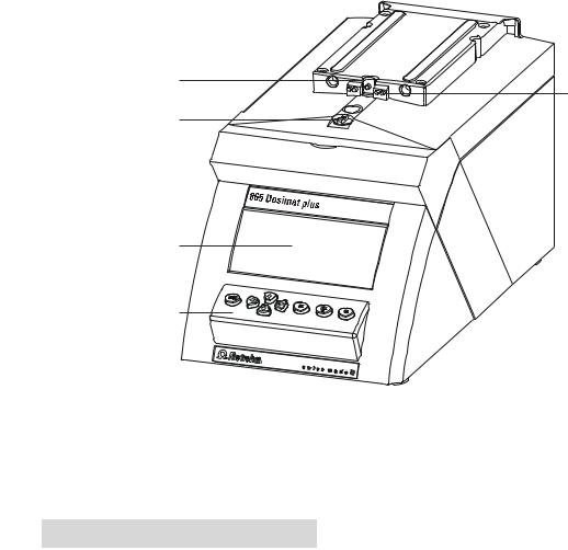
Figure 1 Front 865 Dosimat plus
1 |
Piston rod |
|
2 |
Contact pins |
|
Of the dosing drive. |
|
|
For the data chip. |
|
|
|
|
|
|
|
|
|
|
3 |
Coupling |
|
4 |
Display |
|
For switching the flat stopcock. |
|
|
|
|
|
|
|
|
5Keypad
6 |
865 Dosimat plus |

|
2 Overview of the instrument |
1 |
3 |
|
|
|
4 |
2 |
5 |
|
Figure 2 Rear 865 Dosimat plus
1 Type plate 2 Mains connection socket
Contains specifications concerning mains voltage and serial number.
3USB (OTG) connector
For connecting printers, USB sticks, USB hubs, etc.
5Remote connector
For connecting the Manual Dosing Controller or instruments with a remote interface. D-Sub, 9-pin.
4MSB connector
Metrohm Serial Bus.
For connecting a stirrer or an 805 Dosimat. Mini DIN, 9-pin.
865 Dosimat plus |
7 |

2.2 Manual Dosing Controller |
|
2.2Manual Dosing Controller
1 


 2
2 


 3
3
4
Figure 3 Manual Dosing Controller 6.2107.100
1 |
Dosing key |
|
2 |
Status LED |
|
To start the dosing. |
|
|
Indicates the readiness of the instrument. |
|
|
|
|
|
|
|
|
|
|
3 |
Stop key/Fill key |
|
4 |
Connection cable |
|
For stopping and filling the dosing cylinder. |
|
|
With 9-pin D-Sub plug. |
|
|
|
|
|
8 |
865 Dosimat plus |

|
3 Installation |
3 Installation
3.1Setting up the instrument
3.1.1Packaging
The instrument is supplied in highly protective special packaging together with the separately packed accessories. Keep this packaging, as only this ensures safe transportation of the instrument.
3.1.2Checks
Immediately after receipt, check whether the shipment has arrived complete and without damage by comparing it with the delivery note.
3.1.3Location
The instrument has been developed for operation indoors and may not be used in explosive environments.
Place the instrument in a location of the laboratory which is suitable for operation, free of vibrations, protected from corrosive atmosphere, and contamination by chemicals.
The instrument should be protected against excessive temperature fluctuations and direct sunlight.
3.2Connecting a stirrer
You can connect the following stirrers:
801 Stirrer
803 Ti Stand
804 Ti Stand (requires rod stirrer)
Figure 4 Connecting a stirrer
865 Dosimat plus |
9 |
3.3 Connecting the Manual Dosing Controller |
|
Caution
Make sure that the flat side of the plug matches the marking on the socket.
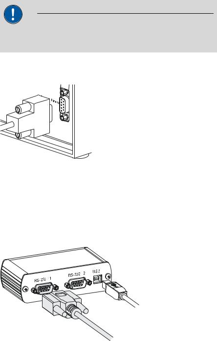
3.3Connecting the Manual Dosing Controller
Figure 5 Connecting the Manual Dosing Controller
The Manual Dosing Controller is connected to the remote connector on the rear of the instrument.
3.4Connecting a balance
Balances are equipped with a serial RS-232 interface as a rule. To connect a balance, you require a 6.2148.030 RS-232/USB Box.
Figure 6 Connecting a balance
When a 6.2151.020 USB cable is used, then the 6.2148.030 RS-232/USB Box can be connected to the 865 Dosimat plus by means of a USB hub or a 6.2151.100 adapter (see Chapter 3.5, page 11).
Connect the 9-pin plug of the respective balance connecting cable to the RS 232/1 connector. Consult the user manual of the balance in order to select the correct connecting cable.
10 |
865 Dosimat plus |
|
3 Installation |
The parameters for the RS-232 interface on the instrument must match those on the balance (see "Editing the COM1 settings", page 35). Additionally consult the user manual of the balance.
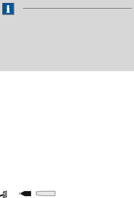
3.5Connecting a keyboard, printer and other USB devices
The 865 Dosimat plus has a USB (OTG) connector. Use the provided 6.2151.100 adapter USB MINI (OTG) - USB A for connecting USB devices as e.g. printers, keyboards or USB sticks, see the following figure.
6.2151.100
Figure 7 Connecting USB devices
Caution
Switch the instrument off before connecting or disconnecting a USB device or a USB stick.
The 865 Dosimat plus can only recognize the device immediately after switching on.
The following devices can be operated directly on the USB connector with the 6.2151.100 adapter:
USB sticks (for the backup or storing of methods)
6.2147.000 numerical USB keypad
6.2148.030 RS-232/USB Box (for connecting balances or for the RS-232 remote control)
USB hub (with or without an own power supply)
The 6.2147.000 numerical USB keypad serves for comfortable numerical input and for navigating in the dialog. In addition, it provides two USB connectors. Connect additional USB devices to the keypad.
865 Dosimat plus |
11 |
3.5 Connecting a keyboard, printer and other USB devices |
|
Note
Most of the USB devices need a so-called hub in order to work correctly.
A USB hub is a distributor to which several USB devices can be connected. USB hubs are available in specialty stores in a number of different models.
The USB (OTG) connector of the 865 Dosimat plus has no such hub. The 6.2147.000 numerical USB keypad has a USB hub and two USB connectors.
The following devices can only be connected to a 6.2147.000 numerical keypad or to a USB hub:
Printer (with USB connector, use the 6.2151.020 connecting cable)
Barcode reader (with USB cable)
Mouse (PC mouse with USB cable, for navigating in the dialog)
The following devices can only be connected to a USB hub:
PC keyboard (with USB cable, for the comfortable input of letters and numbers)
Keypad with numerical keypad (with USB cable)
If you wish to connect several different instruments without own power supply, then you must possibly use a USB hub with own power supply (self powered). The USB (OTG) connector of the 865 Dosimat plus is not designed for supplying power to several devices with elevated electricity requirements.
Also observe the instructions in chapter 8.4, page 63.
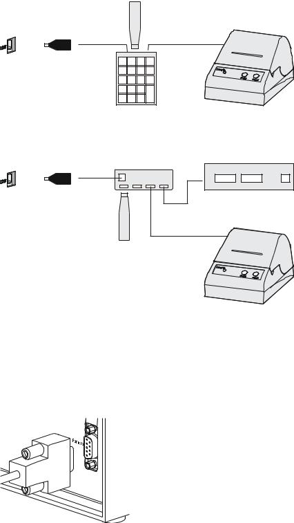
Examples:
USB MINI (OTG)-USB

 USB stick
6.2151.100
Figure 8 Connecting the USB stick
12 |
865 Dosimat plus |
|
3 Installation |
USB MINI (OTG)-USB
6.2151.100
USB stick
Keypad
6.2147.000
Printer
Figure 9 Connecting the 6.2147.000 USB keyboard with USB stick and printer
USB MINI (OTG)-USB
USB-Hub
6.2151.100
USB stick
RS-232/USB Box
6.2148.030
Printer
Figure 10 Connecting the USB hub with USB stick, printer and the 6.2148.030 RS-232/USB Box (for connecting balances).
3.6Connecting instruments to the remote connector
The 865 Dosimat plus can be integrated in an automation system with the aid of a remote cable.
Figure 11 Connecting a remote cable
A variety of different connecting cables are available for connecting Metrohm instruments (e.g. sample changers) (see Optional Accessories chapter).
865 Dosimat plus |
13 |
3.7 Connecting the 805 Dosimat |
|
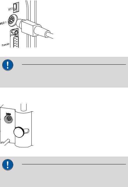
3.7Connecting the 805 Dosimat
For tandem operation (XDOS mode), an 805 Dosimat can be connected to the MSB 1 socket on the rear of the 865 Dosimat plus.
Figure 12 Connecting the 805 Dosimat
Caution
Make sure that the flat side of the plug matches the marking on the socket.
If the MSB 1 connector is already occupied by a stirrer (e.g. 801 Stirrer), then the 805 Dosimat can be connected to the MSB socket of the stirrer.
Figure 13 MSB connector on the 801 Stirrer
Caution
Make sure that the flat side of the plug matches the marking on the socket.
The 865 Dosimat plus must be switched off and then on again after connection.
14 |
865 Dosimat plus |

|
3 Installation |
3.8Attaching the exchange unit
Figure 14 Attaching the exchange unit
To attach the exchange unit, proceed as follows:
1Slide the exchange unit from the front onto the 865 Dosimat plus and push all the way to the rear.
It must snap in audibly.
865 Dosimat plus |
15 |
4.1 Switching the instrument on and off |
|
4Operation
4.1Switching the instrument on and off
Switching on the instrument
Proceed as follows:
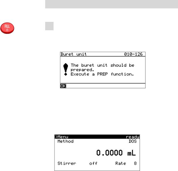
1Press the red [FILL] key.
The instrument is initialized and a system test performed. This process takes some time.
If a buret unit has been attached, then a request appears to carry out the PREP function:
All tubings and the cylinder are rinsed with the PREP (Preparing) function. The preparing of the buret unit is described in chapter
"Preparing the buret unit (PREP)", page 25.
Confirm the message with [OK].
The display of this message can be deactivated in the system settings (see "PREP warning", page 30).
The main dialog is displayed:
16 |
865 Dosimat plus |
|
4 Operation |
Switching off the instrument
The instrument is switched off with the [FILL] key. The fact that the key needs to be pressed down for an extended time prevents accidental switch off.
Proceed as follows:
1Keep the red [FILL] key pressed down for at least 3 s.
A progress bar is displayed. If the key is released during this time, then the instrument will not be switched off.
4.2Fundamentals of operation
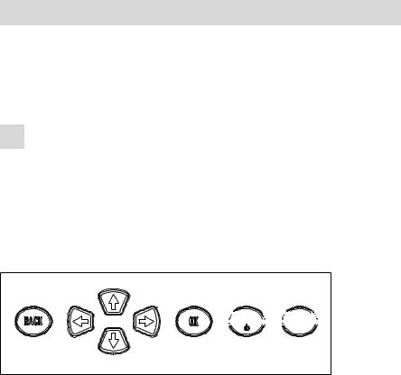
4.2.1The keypad


 FILL
FILL


 GO
GO


Figure 15 Keypad 865 Dosimat plus
BACK |
Apply the input and exit the dialog. |
|
Move the selection bar either up or down by one |
|
line at a time. Select the character to be entered |
|
in the text editor. |
|
Select the character to be entered in the text and |
|
number editor. Select the individual functions in |
|
the function bar. |
OK |
Confirm the selection. |
FILL |
Stop an ongoing method run or a manual func- |
|
tion. Switch the instrument on/off. |
GO |
Start a method run or a manual function. |
865 Dosimat plus |
17 |
4.2 Fundamentals of operation |
|
4.2.2Structure of the dialog windows
The current dialog title is displayed on the left-hand side of the title line. The current status of the system is displayed in the upper right-hand corner:
ready |
The instrument is in normal status. |
busy |
A method has been started. |
hold |
A method has been paused. |
Some dialogs have a so-called function bar on the bottom line. The functions contained therein can be selected with the arrow keys [ ] or [ ] and executed with [OK].
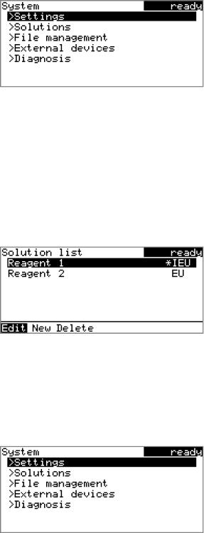
4.2.3Navigating in the dialog
The selection bar is displayed in inverted style. Use the arrow keys [ ] and [ ] to move the selection bar upward or downward one line at a time. If a dialog text is marked with " ", then additional settings are available in a subordinate dialog. Use [OK] to access this dialog.
Example: System settings
Use the [BACK] key to return to the next higher level.
18 |
865 Dosimat plus |
|
4 Operation |
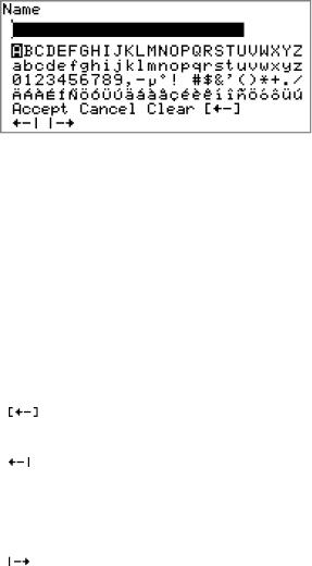
4.2.4Entering text and numbers
In the editing dialog for text or numerical input you can select the individual characters with the arrow keys. Use [OK] to apply the character in the input field. The following functions are available:
Editing function |
Description |
|
|
Accept |
The modification is applied and the editing dialog |
|
is exited. |
|
|
Cancel |
The editing dialog is exited without applying the |
|
modification. |
|
|
Clear |
The content of the input field is deleted com- |
|
pletely. |
|
|
|
The character left of the cursor is deleted (back- |
|
space). |
|
|
|
Text editor only |
|
The cursor within the input field is shifted to the |
|
left by one character each time that [OK] is |
|
pressed. |
|
|
|
Text editor only |
|
The cursor within the input field is shifted to the |
|
right by one character each time that [OK] is |
|
pressed. |
|
|
[BACK] |
The modification is applied and the editing dialog |
|
is exited. |
|
|
The [BACK] key has the same function as Accept.
A commercially available USB keyboard can be connected to make it easier to enter text and numbers. The key assignment on the PC keyboard is described in chapter 8.4.2, page 64.
865 Dosimat plus |
19 |

4.3 Methods |
|
4.2.5Selecting from a selection list
In a selection list, select the individual entries with the arrow keys [ ] and [ ]. Accept the selection with [OK] or [BACK].
4.3Methods
4.3.1Method templates
The 865 Dosimat plus contains method templates which are already configured and which can be adjusted to individual requirements.
The following method templates can be selected:
DOS |
Manual interactive dosing with optional calcula- |
|
tion of results. |
|
For manual titrations. |
XDOS |
Automatic dosing with freely selectable specifi- |
|
cations. |
|
The following specifications are possible: |
|
Volume and time |
|
Volume and dosing rate |
|
Dosing rate and time |
CNT D |
Automatic preparation of solutions with speci- |
|
fied content. |
|
For standard solutions, sample solutions or dilu- |
|
tions. |
LQT |
Liquid handling - sample transfer. |
|
Pipetting with or without after-rinsing and/or |
|
dilution. |
You will find a detailed description of the methods in chapter .
20 |
865 Dosimat plus |
Loading...