


 Loading...
815 Robotic USB Sample Processor XL
Manual
8.815.8003EN

Metrohm AG CH-9101 Herisau Switzerland
Phone +41 71 353 85 85 Fax +41 71 353 89 01 info@metrohm.com www.metrohm.com
815 Robotic USB Sample Processor
XL
Manual
8.815.8003EN |
01/2010 dm |
Teachware Metrohm AG CH-9101 Herisau
teachware@metrohm.com
This documentation is protected by copyright. All rights reserved.
Although all the information given in this documentation has been checked with great care, errors cannot be entirely excluded. Should you notice any mistakes please send us your comments using the address given above.
Documentation in additional languages can be found on http://products.metrohm.com under Literature/Technical documentation.
|
Table of contents |
Table of contents
1 Introduction |
1 |
||
1.1 |
The 815 Robotic USB Sample Processor XL in the |
|
|
|
|
Titrando system .................................................................... |
1 |
1.2 |
|
Instrument description ......................................................... |
2 |
1.2.1 |
Model versions ........................................................................ |
3 |
|
1.2.2 |
Instrument components .......................................................... |
4 |
|
1.2.3 |
Intended use ........................................................................... |
5 |
|
1.3 |
|
About the documentation ................................................... |
5 |
1.3.1 |
Symbols and conventions ........................................................ |
5 |
|
1.4 |
|
Safety instructions ................................................................ |
6 |
1.4.1 |
General notes on safety ........................................................... |
6 |
|
1.4.2 |
Electrical safety ........................................................................ |
6 |
|
1.4.3 |
Tubing and capillary connections ............................................. |
7 |
|
1.4.4 |
Personnel safety ...................................................................... |
8 |
|
1.4.5 |
Flammable solvents and chemicals ........................................... |
9 |
|
1.4.6 |
Recycling and disposal ............................................................. |
9 |
|
2 Overview of the instrument |
10 |
|
2.1 |
Front and rear ..................................................................... |
10 |
2.2 |
Rear panel ........................................................................... |
12 |
2.3 |
Sample racks ....................................................................... |
13 |
3 Installation |
|
14 |
3.1 |
Setting up the instrument .................................................. |
14 |
3.1.1 |
Packaging .............................................................................. |
14 |
3.1.2 |
Checks .................................................................................. |
14 |
3.1.3 |
Location ................................................................................ |
14 |
3.2 |
Preparing the Sample Processor ....................................... |
14 |
3.2.1 |
Connecting a mains cable ...................................................... |
14 |
3.3 |
Connecting a computer ..................................................... |
15 |
3.4 |
Mounting the Swing Head to the Sample Processor ...... |
17 |
3.4.1 |
Mounting the Swing Head ..................................................... |
17 |
3.4.2 |
Guide chain for cables and tubing ......................................... |
19 |
3.4.3 |
Mounting the robotic arm reinforcement ............................... |
21 |
3.5 |
Configuring the robotic arm .............................................. |
22 |
3.6 |
Mounting the robotic arm ................................................. |
24 |
3.7 |
Robotic arms with beaker sensor ..................................... |
26 |
3.8 |
Installing rinsing and aspiration equipment .................... |
27 |
815 Robotic USB Sample Processor XL |
III |
Table of contents |
|
|
|
|
|
3.9 |
Guide chain for cables and tubing .................................... |
|
29 |
|
3.10 |
Equipping the titration head ............................................. |
|
31 |
|
3.11 |
Connecting the tower stirrer ............................................. |
|
33 |
|
3.12 |
Connecting an external pump ........................................... |
|
34 |
|
3.13 |
Connecting MSB devices ................................................... |
|
35 |
|
3.13.1 |
Connecting dosing devices .................................................... |
|
36 |
|
3.13.2 Connecting a stirrer or titration stand .................................... |
|
37 |
|
|
3.13.3 Connecting a remote box ...................................................... |
|
38 |
|
|
3.14 |
Connecting USB devices ..................................................... |
|
39 |
|
3.14.1 Connecting a barcode reader ................................................. |
|
39 |
|
|
3.15 |
Mounting the base plate ................................................... |
|
40 |
|
3.16 |
Mounting the drip pan ....................................................... |
|
42 |
|
3.17 |
Attaching the sample rack ................................................. |
|
43 |
|
3.18 |
Mounting the safety shield ................................................ |
|
44 |
4 |
Handling and maintenance |
|
45 |
|
|
4.1 |
General ................................................................................ |
|
45 |
|
4.2 |
Care ...................................................................................... |
|
45 |
|
4.3 |
Quality Management and validation with Metrohm ....... |
45 |
|
5 |
Troubleshooting |
|
46 |
|
|
5.1 |
Sample Processor ............................................................... |
|
46 |
|
5.2 |
Robotic arm ......................................................................... |
|
46 |
|
5.3 |
Pump .................................................................................... |
|
47 |
6 |
Appendix |
|
|
48 |
|
6.1 |
Beaker sensor ..................................................................... |
|
48 |
|
6.2 |
Rinsing nozzles ................................................................... |
|
48 |
|
6.3 |
Remote interface ................................................................ |
|
49 |
|
6.3.1 Pin assignment of the remote interface .................................. |
|
50 |
|
|
6.4 |
Robotic arms ....................................................................... |
|
51 |
|
6.4.1 Robotic arms for titration ....................................................... |
|
51 |
|
|
6.4.2 Robotic arms for sample preparation ..................................... |
|
53 |
|
|
6.4.3 Robotic arms for special applications ..................................... |
|
54 |
|
7 |
Technical specifications |
|
56 |
|
|
7.1 |
Lift and turntable ............................................................... |
|
56 |
|
7.2 |
Membrane pump(s) with valve .......................................... |
|
56 |
|
7.3 |
Interfaces and connectors ................................................. |
|
56 |
IV |
815 Robotic USB Sample Processor XL |
|
|
Table of contents |
|
|
7.4 |
Mains connection ............................................................... |
57 |
|
7.5 |
Safety specifications ........................................................... |
57 |
|
7.6 |
Electromagnetic compatibility (EMC) ................................ |
57 |
|
7.7 |
Ambient temperature ......................................................... |
58 |
|
7.8 |
Reference conditions .......................................................... |
58 |
|
7.9 |
Dimensions .......................................................................... |
58 |
8 |
Conformity and warranty |
59 |
|
|
8.1 |
Declaration of Conformity ................................................. |
59 |
|
8.2 |
Warranty (guarantee) ......................................................... |
60 |
|
8.3 |
Quality Management Principles ........................................ |
61 |
9 |
Accessories |
|
63 |
9.1Scope of delivery 815 Robotic USB Sample Processor
XL 2.815.0010 .................................................................... |
63 |
9.2Scope of delivery 815 Robotic USB Sample Processor
XL 2.815.0020 .................................................................... |
68 |
9.3Scope of delivery 815 Robotic USB Sample Processor
XL 2.815.0030 .................................................................... |
74 |
9.4Scope of delivery 815 Robotic USB Sample Processor
XL 2.815.0110 .................................................................... |
76 |
9.5Scope of delivery 815 Robotic USB Sample Processor
XL 2.815.0120 .................................................................... |
81 |
9.6Scope of delivery 815 Robotic USB Sample Processor
XL 2.815.0130 .................................................................... |
87 |
9.7 Optional accessories ........................................................... |
90 |
Index |
104 |
815 Robotic USB Sample Processor XL |
V |
Table of figures |
|
Table of figures |
|
|
Figure 1 |
The Titrando system .......................................................................... |
1 |
Figure 2 |
Front 815 Robotic USB Sample Processor XL .................................... |
10 |
Figure 3 |
Rear 815 Robotic USB Sample Processor XL ..................................... |
11 |
Figure 4 |
Connector strip ............................................................................... |
12 |
Figure 5 |
6.2041.840 Sample rack ................................................................. |
13 |
Figure 6 |
Connecting the mains cable ............................................................ |
14 |
Figure 7 |
Connecting the computer ............................................................... |
15 |
Figure 8 |
Connecting Swing Head .................................................................. |
17 |
Figure 9 |
Mounting the tower extension ........................................................ |
19 |
Figure 10 |
Mounting the Swing Head to the tower extension ........................... |
19 |
Figure 11 |
Guide chain - Opening chain links ................................................... |
20 |
Figure 12 |
Mounting the 6.2058.090 robotic arm reinforcement ..................... |
21 |
Figure 13 |
Robotic arms - standard model versions: ......................................... |
22 |
Figure 14 |
Configuration data of the robotic arms ............................................ |
23 |
Figure 15 |
Limitation screw at the robotic arm ................................................. |
24 |
Figure 16 |
Mounting the robotic arm ............................................................... |
25 |
Figure 17 |
Connecting a beaker sensor (for example 6.1462.150) .................... |
26 |
Figure 18 |
Mounting the rinsing and aspiration tubings .................................... |
27 |
Figure 19 |
Mounting the distributor ................................................................. |
29 |
Figure 20 |
Guide chain - Opening chain links ................................................... |
30 |
Figure 21 |
Installing the rinsing tubings and the aspiration tip .......................... |
31 |
Figure 22 |
Rod stirrer 802 Stirrer ...................................................................... |
33 |
Figure 23 |
Magnetic stirrer 741 Stirrer .............................................................. |
33 |
Figure 24 |
Connecting the tower stirrer ............................................................ |
33 |
Figure 25 |
Connecting the pump ..................................................................... |
34 |
Figure 26 |
Connecting a dosing device ............................................................. |
36 |
Figure 27 |
Connecting MSB stirrer .................................................................... |
37 |
Figure 28 |
Rod stirrer and titration stand .......................................................... |
37 |
Figure 29 |
Connecting a remote box ................................................................ |
38 |
Figure 30 |
USB connectors ............................................................................... |
39 |
Figure 31 |
Mounting the base plate ................................................................. |
41 |
Figure 32 |
Installing the drip pan ...................................................................... |
42 |
Figure 33 |
Attaching the rack ........................................................................... |
43 |
Figure 34 |
Mount the safety shield ................................................................... |
44 |
Figure 35 |
Beaker sensor on the tower ............................................................. |
48 |
Figure 36 |
Spray nozzles - Functioning ............................................................. |
49 |
Figure 37 |
Connectors of the remote box ......................................................... |
49 |
Figure 38 |
Pin assignment of the remote socket and plug ................................ |
50 |
VI |
815 Robotic USB Sample Processor XL |
|
1 Introduction |
1 Introduction
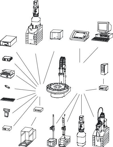
1.1The 815 Robotic USB Sample Processor XL in the Titrando system
The 815 Robotic USB Sample Processor XL is a component of the modular Titrando system. Operation is carried out by a Touch Control with touchsensitive screen ("Stand alone" titrator) or by a computer with a corresponding software.
A Titrando system can contain numerous, various kinds of devices. The following figure provides an overview of the peripheral devices you can connect to the 815 Robotic USB Sample Processor XL.
|
|
pH Module |
Touch Control |
Personal Computer |
|
Titrando |
Conductivity Module |
|
|
Dosing Interface |
|
|
|
|
|
|
|
|
|
USB Lab Link |
|
|
Controller |
|
|
|
|
|
|
|
|
|
|
Relay Box |
Printer |
|
|
|
|
Bluetooth USB |
|
USB |
MSB |
Remote Box |
Adapter |
|
|
|
|
|
|
|
|
|
|
|
USB Sample Processor |
|
|
PC Keyboard |
|
Robotic Titrosampler |
|
|
|
|
|
|
RS-232/USB Box
Barcode
Reader
USB Hub
|
|
|
8mDi50soa |
|
|
|
Mrothe |
Balance |
Stirrer / Ti Stand |
Dosino |
Dosimat |
Figure 1 The Titrando system
815 Robotic USB Sample Processor XL |
1 |
1.2 Instrument description |
|
Up to three control devices (Titrandos, Dosing Interfaces, USB Sample Processors etc.) can be controlled via USB connection by the Touch Control. With the tiamo software the system can arbitrarily be extended with control devices.
Updating the device software is described in the manual for the Touch
Control or in the tiamo help, respectively.
1.2Instrument description
The 815 Robotic USB Sample Processor XL is a versatile instrument. It has been designed exclusively for usage in factories and laboratories and thereby covers a wide range of applications.
Thanks to the integration of high-performance USB interfaces, it can be incorporated seamlessly into a Metrohm Titrando system. The various communication possibilities of the Titrando system (Remote Box, LIMS connection etc.) can thus all be used. Thanks to these abilities, a 815 Robotic USB Sample Processor XL is predetermined for all kind of automation tasks in a modern laboratory, especially for highly integrated laboratory data systems.
The user interface of the Touch Control or the tiamo™ software guarantees comfortable operation and programming of the 815 Robotic USB Sample Processor XL. The comprehensive range of commands and the various configuration possibilities can comfortably and efficiently be used this way. The integration into the Titrando system also guarantees a 100% conformity of the complete automation system according to the regulations of the FDA (Federal Drug Administration), especially to the regulation 21 CFR part 11, electronic records and signatures.
There are exchangeable standard sample racks available for many vessel dimensions. Freely selectable "Special beaker" positions can be defined for e.g. rinsing or conditioning beakers on every rack.
The number of samples to be processed on a rack can considerably be increased by upgrading with a 786 Swing Head. The robotic arms for the 786 Swing Head make it possible to move to any given point on a sample rack. This way the number (a maximum of 999 rack positions) and sequencing of the samples is almost completely unlimited.
Customer-specific special racks for individual requirements can be fabricated upon request.
2 |
815 Robotic USB Sample Processor XL |
|
1 Introduction |
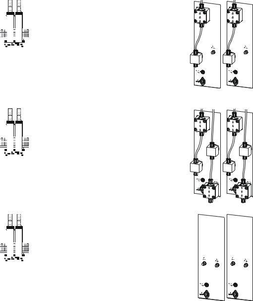
1.2.1Model versions
The 815 Robotic USB Sample Processor XL is available in the following versions with different components.
2.815.0010
1-Tower version
1 membrane pumpe and 1 valve1 connector for an external pump1 stirrer connector (tower stirrer)1 Swing Head connector
3 MSB connectors for dosing devices or stirrers2 USB connectors
1 controller connection
2.815.0020
1-Tower version
2 membrane pumps and 2 valves1 stirrer connector (tower stirrer)1 Swing Head connector
3 MSB connectors for dosing devices or stirrers2 USB connectors
1 controller connection
2.815.0030
1-Tower version
2 connectors for external pumps1 stirrer connector (tower stirrer)1 Swing Head connector
3 MSB connectors for dosing devices or stirrers
2 USB connectors
1 controller connection
815 Robotic USB Sample Processor XL |
3 |
1.2 Instrument description |
|
2.815.0110
2-Tower version
2 membrane pumps and 2 valves
2 connectors for external pumps
2 stirrer connectors (tower stirrer)
2 Swing Head connectors
3 MSB connectors for dosing devices or stirrers
2 USB connectors
1 controller connection
2.815.0120
2-Tower version
4 membrane pumps and 4 valves2 stirrer connectors (tower stirrer)2 Swing Head connectors
3 MSB connectors for dosing devices or stirrers
2 USB connectors
1 controller connection
2.815.0130
2-Tower version
4 connectors for external pumps2 stirrer connectors (tower stirrer)2 Swing Head connectors
3 MSB connectors for dosing devices or stirrers
2 USB connectors
1 controller connection
1.2.2Instrument components
The 815 Robotic USB Sample Processor XL has the following components:
Turntable
For sample racks with a diameter of up to 48 cm.
One or two towers with lift
With titration head holder. Each lift can subsequently be extended by a Swing Head and a robotic arm.
One, two or no membrane pump per tower
Instead of an integrated pump, an external pump connector is available depending on the model version.
4 |
815 Robotic USB Sample Processor XL |
|
1 Introduction |
One stirrer connector per tower
For connecting a rod stirrer (802 Stirrer) or a magnetic stirrer (741 Stirrer).
Controller connection
For connecting a PC or Touch Control.
Two USB connectors
For connecting a printer, barcode reader or other control devices (Titrando, Dosing Interface etc.).
Three MSB connectors (Metrohm Serial Bus)
For connecting dosing devices (Dosimat with exchange unit or Dosino with dosing unit), stirrers or Remote Boxes.
1.2.3Intended use
The 815 Robotic USB Sample Processor XL is designed for usage as an automation system in analytical laboratories. It is not suitable for usage in biochemical, biological or medical environments in its basic equipment version.
The present instrument is suitable for processing chemicals and flammable samples. The usage of the 815 Robotic USB Sample Processor XL therefore requires that the user has basic knowledge and experience in the handling of toxic and caustic substances. Knowledge with respect to the application of the fire prevention measures prescribed for laboratories is also mandatory.
1.3About the documentation
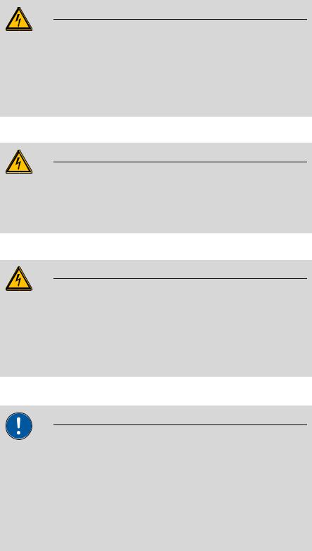
Caution
Please read through this documentation carefully before putting the instrument into operation. The documentation contains information and warnings which the user must follow in order to ensure safe operation of the instrument.
1.3.1Symbols and conventions
The following symbols and styles are used in this documentation:
Cross-reference to figure legend
The first number refers to the figure number, the second to the instrument part in the figure.
Instruction step
Carry out these steps in the sequence shown.
815 Robotic USB Sample Processor XL |
5 |
1.4 Safety instructions |
|
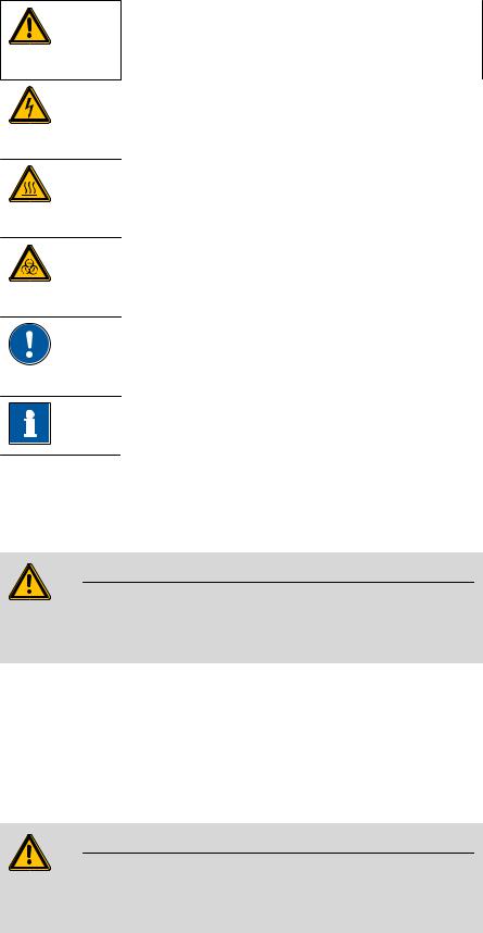
Warning
This symbol draws attention to a possible life hazard or risk of injury.
Warning
This symbol draws attention to a possible hazard due to electrical current.
Warning
This symbol draws attention to a possible hazard due to heat or hot instrument parts.
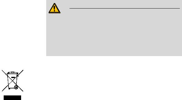
Warning
This symbol draws attention to a possible biological hazard.
Caution
This symbol draws attention to a possible damage of instruments or instrument parts.
Note
This symbol marks additional information and tips.
1.4Safety instructions
1.4.1General notes on safety
Warning
This instrument may only be operated in accordance with the specifications in this documentation.
This instrument has left the factory in a flawless state in terms of technical safety. To maintain this state and ensure non-hazardous operation of the instrument, the following instructions must be observed carefully.
1.4.2Electrical safety
The electrical safety when working with the instrument is ensured as part of the international standard IEC 61010.
Warning
Only personnel qualified by Metrohm are authorized to carry out service work on electronic components.
6 |
815 Robotic USB Sample Processor XL |
|
1 Introduction |
Warning
Never open the housing of the instrument. The instrument could be damaged by this. There is also a risk of serious injury if live components are touched.
There are no parts inside the housing which can be serviced or replaced by the user.
Mains voltage
Warning
An incorrect mains voltage can damage the instrument.
Only operate this instrument with a mains voltage specified for it (see rear panel of the instrument).
Protection against electrostatic charges
Warning
Electronic components are sensitive to electrostatic charges and can be destroyed by discharges.
Always pull the mains cable out of the mains connection socket before connecting or disconnecting electrical appliances on the rear panel of the instrument.
1.4.3Tubing and capillary connections
Caution
Leaks in tubing and capillary connections are a safety risk. Tighten all connections well by hand. Avoid applying excessive force to tubing connections. Damaged tubing ends lead to leakage. Appropriate tools can be used to loosen connections.
Check the connections regularly for leakage. If the instrument is used mainly in unattended operation, then weekly inspections are mandatory.
815 Robotic USB Sample Processor XL |
7 |

1.4 Safety instructions |
|
1.4.4Personnel safety
Warning
Wear protective goggles and working clothes suitable for laboratory work while operating the 815 Robotic USB Sample Processor XL. It is also advisable to wear gloves when caustic liquids are used or in situations where glass vessels could break.
Warning
Always install the safety shield supplied with the equipment before using the instrument for the first time. Pre-installed safety shields are not allowed to be removed.
The 815 Robotic USB Sample Processor XL may not be operated without a safety shield!
Warning
Personnel are not permitted to reach into the working area of the instrument while operations are running!
A considerable risk of injury exists for the user.
Warning
In the event of a possible blockage of a drive, the mains plug must be pulled out of the socket immediately. Do not attempt to free jammed sample vessels or other parts while the device is switched on. Blockages can only be cleared when the instrument is in a voltage-free status; this action generally involves a considerable risk of injury.
Warning
The 815 Robotic USB Sample Processor XL is not suitable for utilization in biochemical, biological or medical environments in its basic equipment version.
Appropriate protective measures must be implemented in the event that potentially infectious samples or reagents are being processed.
8 |
815 Robotic USB Sample Processor XL |
|
1 Introduction |
1.4.5Flammable solvents and chemicals
Warning
All relevant safety measures are to be observed when working with flammable solvents and chemicals.
Set up the instrument in a well-ventilated location.
Keep all sources of flame far from the workplace.
Clean up spilled liquids and solids immediately.
Follow the safety instructions of the chemical manufacturer.
1.4.6Recycling and disposal
This product is covered by European Directive 2002/96/EC, WEEE – Waste from Electrical and Electronic Equipment.
The correct disposal of your old equipment will help to prevent negative effects on the environment and public health.
More details about the disposal of your old equipment can be obtained from your local authorities, from waste disposal companies or from your local dealer.
815 Robotic USB Sample Processor XL |
9 |

2.1 Front and rear |
|
2 Overview of the instrument
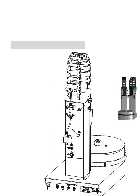
2.1Front and rear
5


 6 1
6 1 


7
2
8
9
3
4
Figure 2 Front 815 Robotic USB Sample Processor XL
10 |
815 Robotic USB Sample Processor XL |
|
|
|
2 Overview of the instrument |
|
|
|
|
|
|
1 |
Safety shield (6.2751.100) |
|
2 |
Sample rack (6.2041.800) |
|
other models, see chap. Accessories. |
|
|
other models, see chap. Accessories. |
|
|
|
|
|
|
|
|
|
|
3 |
Turntable |
|
4 |
Stirrer rail |
|
With guide bolts. |
|
|
For magnetic stirrer (741 Stirrer). |
|
|
|
|
|
|
|
|
|
|
5 |
Guide chain |
|
6 |
Lift |
|
For cables and tubings. |
|
|
With titration head holder. |
|
|
|
|
|
|
|
|
|
|
7 |
786 Swing Head (2.786.0040) |
|
8 |
Robotic arm (6.1462.050) |
|
Drive for a robotic arm. |
|
|
With aspiration and dosing tips. |
|
|
|
|
|
9Beaker sensor
1
8 |
T2 |
T1 |
|
|
2
3
4
5
6
USB 2
7 


Figure 3 Rear 815 Robotic USB Sample Processor XL
815 Robotic USB Sample Processor XL |
11 |
2.2 Rear panel |
|
|
|
|
|
|
|
|
|
1 |
Distributor |
|
2 |
Membrane pump |
|
For rinsing equipment. |
|
|
Pump 1. |
|
|
|
|
|
|
|
|
|
|
3 |
Pump connection |
|
4 |
Pump valve |
|
Pump 2. For the external pump. |
|
|
|
|
|
|
|
|
|
|
|
|
|
5 |
Swing Head connector |
|
6 |
Stirrer connector |
|
Mini DIN socket (9-pin). |
|
|
DIN socket. For rod stirrer (802 Stirrer) or |
|
|
|
|
magnetic stirrer (741 Stirrer). |
|
|
|
|
|
|
|
|
|
|
7 |
Rear panel with connectors |
|
8 |
Warning symbol |
|
|
|
|
(see Chapter 1.4.4, page 8) |
|
|
|
|
|
T1 Tower 1
With a 2-tower model.
T2 Tower 2
With a 2-tower model.
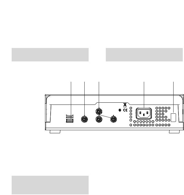
2.2Rear panel
1 |
2 |
3 |
|
4 |
5 |
WARNING - Fire Hazard - |
|
MSB 1 |
P: 115W |
U: 100 - 240 V |
f: 50 - 60 Hz |
For continued protection replace only |
|
|
|
|
|
with the same type and rating of fuse |
|
|
Made by Metrohm |
|
|
|
|
|
|
|
|
USB 2 |
|
|
Herisau Switzerland |
|
|
|
|
|
|
|
|
USB 1 |
Contr. |
MSB 2 |
MSB 3 |
|
Nr. |
Figure 4 Connector strip
1 |
USB connectors |
|
2 |
Controller connector |
|
|
|
|
For the connection to the PC or Touch Con- |
|
|
|
|
trol. |
|
|
|
|
|
|
|
|
|
|
3 |
MSB connector |
|
4 |
Mains connection |
|
For stirrers, dosing devices, Remote Box. |
|
|
|
|
|
|
|
|
5Type plate
Contains specifications concerning mains voltage and serial number.
12 |
815 Robotic USB Sample Processor XL |
|
2 Overview of the instrument |
2.3Sample racks
A sample rack is a turntable that acts as a receptacle for sample vessels. Various types of sample racks are available for different numbers and types of sample vessels.
The 815 Robotic USB Sample Processor XL requires sample racks with up to a maximum of 48 cm diameter.
Figure 5 6.2041.840 Sample rack
Other user-defined racks can be supplied upon request and the required rack data can be loaded and configured in the control software. Any arrangement of rack positions is possible.
Magnet codes
Every single sample rack can be unambiguously identified by means of a magnet code. The Sample Processor can thus recognize automatically which rack is in place.
When replacing a rack, this should first be returned to starting position using the Rack initialization function (see "Manual Control" in the control software). This will enable an unambiguous recognition of the rack and thus the correct positioning of the beaker. A positioning table is assigned to each rack type in which each rack position is defined.
815 Robotic USB Sample Processor XL |
13 |
3.1 Setting up the instrument |
|
3Installation
3.1Setting up the instrument
3.1.1Packaging
The instrument is supplied in highly protective special packaging together with the separately packed accessories. Keep this packaging, as only this ensures safe transportation of the instrument.
3.1.2Checks
Immediately after receipt, check whether the shipment has arrived complete and without damage by comparing it with the delivery note.
3.1.3Location
The instrument has been developed for operation indoors and may not be used in explosive environments.
Place the instrument in a location of the laboratory which is suitable for operation, free of vibrations, protected from corrosive atmosphere, and contamination by chemicals.
The instrument should be protected against excessive temperature fluctuations and direct sunlight.
3.2Preparing the Sample Processor
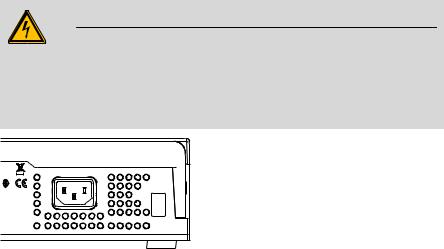
3.2.1Connecting a mains cable
Warning
This instrument must not be operated except with the mains voltage specified for it (see rear panel of the instrument).
Protect the connection sockets against moisture.
P: 115W |
U: 100 - 240 V |
f: 50 - 60 Hz |
|
|
Nr. |
Figure 6 Connecting the mains cable
14 |
815 Robotic USB Sample Processor XL |
|
3 Installation |
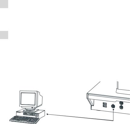
3.3Connecting a computer
The 815 Robotic USB Sample Processor XL requires a USB connection to a computer in order to be able to be controlled by a PC software. When a 6.2151.000 controller cable is used, the instrument can be connected directly, either to a USB socket on a computer, to a connected USB hub or to a different Metrohm control instrument.
Cable connection and driver installation
A driver installation is required in order to ensure that the 815 Robotic USB Sample Processor XL is recognized by the PC software. To accomplish this, you must comply with the procedures specified. The following steps are necessary:
1Installing the software
Insert the PC software installation CD and carry out the installation program directions.
Exit the program if you have started it after the installation.
2Establishing cable connections
Connect all peripheral devices to the instrument (see Chapter 3.13, page 35).
Connect the 815 Robotic USB Sample Processor XL to the mains supply if you have not already done this.
Connect the instrument to your computer through a USB connector (Type A) (see Instructions for Use for your computer). The 6.2151.000 cable is used for this purpose.
6.2151.000
USB 2
USB 1
Contr.
MSB 2
Figure 7 Connecting the computer
For Windows 2000: The instrument is recognized and the driver is installed automatically.
For Windows XP: The instrument is recognized and the installation assistant for the driver is started automatically. Select the option "Install software automatically" and click on [Continue]. Exit the assistant with [Finish].
815 Robotic USB Sample Processor XL |
15 |

3.3 Connecting a computer |
|
For Windows Vista: The instrument is recognized and the installation assistant for the driver is started automatically. Select the option "Find and install driver software". Agree to all subsequent requests.
The installation assistant will be exited automatically.
Note
The plug on the instrument end of the 6.2151.000 controller cable is protected with an anti-pull device to prevent the cable from being pulled out accidentally. If you wish to pull out the plug, then you must first retract the outer plug sleeve marked with arrows.
Registering and configuring the instrument in the PC software
The instrument must be registered in the configuration of your PC software. Once that has been done, you can then configure it according to your requirements. Proceed as follows:
1Setting up the instrument
Start up the PC software.
The instrument is recognized automatically. The configuration dialog for the instrument is displayed.
Make configuration settings for the instrument and its connectors.
More detailed information concerning the configuration of the instument can be found in the documentation for the respective PC software.
16 |
815 Robotic USB Sample Processor XL |
|
3 Installation |
3.4Mounting the Swing Head to the Sample Processor
3.4.1Mounting the Swing Head
Dismounting the titration head holder
1 |
|
2 |
1 |
1 Loosen the screws of the holder on both sides.
2Loosen and remove the holder from the holder plate of the guide chain.
Use the hexagon key provided. The screws will be needed again later.
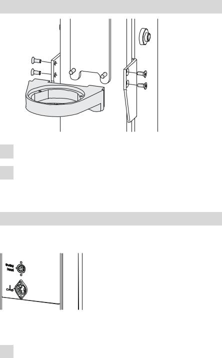
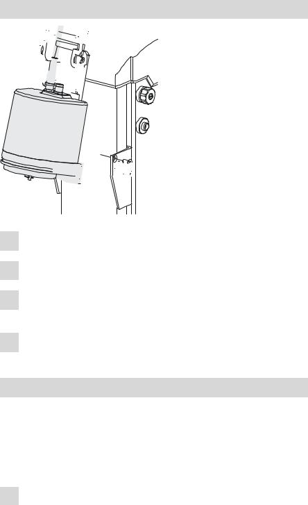
Connecting the Swing Head
The connection socket (Mini DIN) for the Swing Head drive is each located on the rear of the tower next to the stirrer connector.
Figure 8 Connecting Swing Head
Connect the Swing Head as follows:
1Plug in the cable
Guide the connection cable of the Swing Head through the guide chain of the tower (see Chapter 3.4.2, page 19).
815 Robotic USB Sample Processor XL |
17 |
3.4 Mounting the Swing Head to the Sample Processor |
|
Plug the Mini DIN plug into the socket 'Swing Head'.
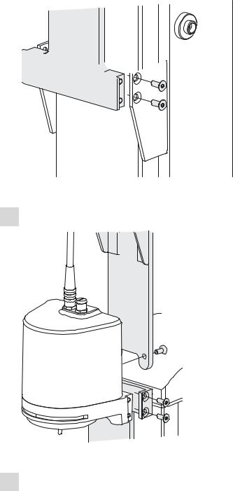
Mounting the Swing Head


 4
4


 1
1 


 2
2


 3
3
1 Screw the Swing Head tightly to the holder plate of the guide chain.
2 Clamp the Swing Head between the guide jaws.
3Screw the Swing Head to the guide jaws with the screws previously loosened.
4Place the connection cable into the guide chain (see Chapter 3.4.2, page 19).
Mounting the Swing Head with tower extension
For certain applications, it may be necessary to mount the 815 Robotic USB Sample Processor XL at a higher position. A 6.2058.010 tower extension can be mounted on the lift for this purpose.
First, remove the titration head holder from its mount (see Chapter 3.4.1, page 17). Proceed afterwards as follows:
1Fasten the tower extension to the lift guide of the Sample Processor in accordance with the following illustration and fix it in place with the screws provided.
18 |
815 Robotic USB Sample Processor XL |
|
3 Installation |
 1
1

Figure 9 Mounting the tower extension
2 Mount the Swing Head to the holder plate of the guide chain.
2

 3
3
Figure 10 Mounting the Swing Head to the tower extension
3Screw the Swing Head tightly to the upper end of the tower extension.
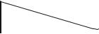
3.4.2Guide chain for cables and tubing
Tubings and cables can be placed into the guide chain.
815 Robotic USB Sample Processor XL |
19 |
3.4 Mounting the Swing Head to the Sample Processor |
|
You can open the individual chain links with a screwdriver as follows.
1Open the guide chain
Insert a screwdriver into the groove located on the side of a chain link.
Loosen the clip with a forceful leverage movement.
Pull the clip out of the chain by hand.
Repeat the above actions for each chain link.
Figure 11 Guide chain - Opening chain links
2Insert into the guide chain
Place the required tubings or cables into the guide chain.
3Close the guide chain
Close the clip for each chain link again by hand and apply forceful pressure to snap them into place.
Caution
Take care to ensure when mounting tubing and cables that there is no traction on the drives while moving the lift or swiveling the robotic arm. This could lead to overloading of and possible damage to the drive.
Remove the clips of the two lowest chain links when you install the rinsing and aspiration tubing.
20 |
815 Robotic USB Sample Processor XL |
|
3 Installation |
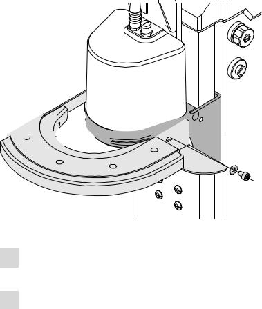
3.4.3Mounting the robotic arm reinforcement
In cases in which it is necessary to take up or strip off a filter or a pipetting tip on the robotic arm, you must mount a 6.2058.090 robotic arm reinforcement. The reinforcement provides the robotic arm with stable resistance when picking up or stripping the tools used and prevents it from bending.
The reinforcement has to be placed before mounting a robotic arm. Proceed as follows:


 1
1 


 2
2
6.2058.090
Figure 12 Mounting the 6.2058.090 robotic arm reinforcement
1Shift the reinforcement from the front over the holder plate of the Swing Head.
2 Screw the reinforcement to the lift guide with the screws provided.
815 Robotic USB Sample Processor XL |
21 |
3.5 Configuring the robotic arm |
|
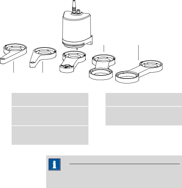
3.5Configuring the robotic arm
A variety of differently constructed robotic arms is available for enabling a wide range of applications. They differ from one another in their geometric sizes, e.g. swing radius or maximum permissible swing angle. The configuration data must be entered in the Sample Processor or in the control software prior to the assembly of the robotic arm. The data required is engraved on the underside of the robotic arm. Examples of the most common robotic arms are shown in the illustration below.
4 |
5 |
1 |
2 |
3 |
Figure 13 Robotic arms - standard model versions:
1Transfer robotic arm (6.1462.030)
For sample transfer, left-swinging.
3Titration robotic arm (6.1462.050)
With titration head, left-/right-swinging *).
5Macro robotic arm (6.1462.070)
With holder for a 6.1458.XXX titration head insert, right-swinging.
2Transfer robotic arm (6.1462.040)
For sample transfer, right-swinging.
4Macro robotic arm (6.1462.060)
With holder for a 6.1458.XXX titration head insert, left-swinging.
*) can be mounted in two ways
Note
A detailed list of the available robotic arms, along with the necessary configuration data, can be found in Chapter Robotic arms, page 51ff.
22 |
815 Robotic USB Sample Processor XL |
Loading...