


 Loading...
819 IC Detector
820 IC Separation Center
CH-9101 Herisau/Switzerland E-Mail info@metrohm.com Internet www.metrohm.com
5.819.0010 Program
Instructions for Use 8.819.1013

CH-9101 Herisau/Switzerland
E-Mail info@metrohm.com
Internet www.metrohm.com
819 IC Detector
820 IC Separation Center
5.819.0010 Program
Instructions for Use
8.819.1013 |
05.2004 / pkl |
Teachware
Metrohm AG Oberdorfstrasse 68 CH-9101 Herisau teachware@metrohm.com
2nd Edition 2004
These instructions are protected by copyright. All rights reserved.
Although all the information given in these instructions has been checked with great care, errors cannot be entirely excluded. Should you notice any mistakes please inform the author at the address given above.

|
|
|
|
Table of contents |
|
|
|
|
|
|
|
Table of contents |
|
|
1 |
Introduction.................................................... |
1 |
||
|
1.1 |
Instrument description ............................................................. |
1 |
|
|
|
1.1.1 |
819 IC Detector ............................................................................. |
1 |
|
|
1.1.2 |
820 IC Separation Center.............................................................. |
2 |
|
|
1.1.3 |
Schematic arrangement of the IC systems................................... |
3 |
|
1.2 |
Parts and controls .................................................................... |
4 |
|
|
|
1.2.1 |
819 IC Detector ............................................................................. |
4 |
|
|
1.2.2 |
820 IC Separation Center.............................................................. |
6 |
|
1.3 |
Information on the Instructions for Use ................................ |
10 |
|
|
|
1.3.1 |
Organization ................................................................................ |
10 |
|
|
1.3.2 |
Notation and pictograms ............................................................ |
11 |
|
1.4 |
Safety notes ............................................................................ |
12 |
|
|
|
1.4.1 |
General precautionary rules........................................................ |
12 |
2 |
Installation ................................................... |
13 |
||
|
2.1 |
Setting up the instrument....................................................... |
13 |
|
|
|
2.1.1 |
Packaging.................................................................................... |
13 |
|
|
2.1.2 |
Check........................................................................................... |
13 |
|
|
2.1.3 |
Location....................................................................................... |
13 |
|
|
2.1.4 |
Arrangement of the instruments.................................................. |
13 |
|
2.2 |
Installation of accessories ..................................................... |
15 |
|
|
|
2.2.1 |
Insert detector block.................................................................... |
15 |
|
|
2.2.2 |
Connection of column heating.................................................... |
18 |
|
|
2.2.3 |
Connection of syringe and aspirating tubing.............................. |
19 |
|
|
2.2.4 |
Connection of the drain tube....................................................... |
19 |
|
|
2.2.5 |
Connection of the 6.5324.000 Bottle rack (option)..................... |
19 |
|
2.3 |
Electrical connection .............................................................. |
20 |
|
|
|
2.3.1 |
Connection to 830 IC Interface ................................................... |
20 |
|
|
2.3.2 |
Connection to PC ........................................................................ |
23 |
|
2.4 |
Mains connection.................................................................... |
25 |
|
|
|
2.4.1 |
819 IC Detector ........................................................................... |
25 |
|
|
2.4.2 |
820 IC Separation Center............................................................ |
27 |
|
|
2.4.3 |
Column heating ........................................................................... |
27 |
|
2.5 |
Software-installation............................................................... |
27 |
|
|
2.6 |
Capillary connections............................................................. |
28 |
|
|
2.7 |
Connection of 818 IC Pump ................................................... |
29 |
|
|
|
2.7.1 |
Electrical connection ................................................................... |
29 |
|
|
2.7.2 |
Pulsation dampener .................................................................... |
29 |
|
|
2.7.3 |
Filter unit PEEK............................................................................ |
30 |
|
|
2.7.4 |
Connection to injection valve ...................................................... |
31 |
|
2.8 |
Precolumns ............................................................................. |
33 |
|
|
2.9 |
Separating columns and suppressor module....................... |
34 |
|
|
|
2.9.1 |
General information on separating columns .............................. |
34 |
|
|
2.9.2 |
Installing a separating column in the column heating................ |
35 |
|
|
2.9.3 |
Selection of the sample loop ...................................................... |
37 |
|
|
2.9.4 |
General information on suppressor module............................... |
37 |
|
|
2.9.5 |
One-channel system without suppressor module...................... |
39 |
|
|
2.9.6 |
Two-channel system without suppressor module...................... |
41 |
|
|
2.9.7 |
One-channel system with suppressor module ........................... |
42 |
|
|
2.9.8 |
Two-channel system with suppressor module ........................... |
47 |
|
|
2.9.9 |
Leak testing and conditioning..................................................... |
48 |
819 IC Detector / 820 IC Separation Center |
I |

Table of contents
3 Operation ...................................................... |
50 |
|
3.1 |
819 IC Detector ....................................................................... |
50 |
|
3.1.1 819 IC Detector icon ................................................................... |
50 |
|
3.1.2 Settings in the "819 IC Detector" window.................................... |
50 |
3.2 |
820 IC Separation Center ....................................................... |
60 |
|
3.2.1 820 IC Separation Center icon.................................................... |
60 |
|
3.2.2 "820 IC Separation Center" window ............................................ |
60 |
4 Notes – Maintenance – Faults...................... |
66 |
||
4.1 Practical notes on ion chromatography ................................ |
66 |
||
|
4.1.1 |
Separating columns .................................................................... |
66 |
|
4.1.2 |
Pumps ......................................................................................... |
67 |
|
4.1.3 |
Eluents......................................................................................... |
68 |
|
4.1.4 |
Suppressor module..................................................................... |
69 |
|
4.1.5 |
Connections ................................................................................ |
69 |
4.2 |
Maintenance and servicing .................................................... |
69 |
|
|
4.2.1 |
General information..................................................................... |
69 |
|
4.2.2 |
Passivation .................................................................................. |
70 |
|
4.2.3 |
Recycling..................................................................................... |
70 |
|
4.2.4 |
Shutdown .................................................................................... |
70 |
|
4.2.5 |
Changing separating columns ................................................... |
71 |
|
4.2.6 |
Regeneration of suppressor ....................................................... |
72 |
|
4.2.7 |
Cleaning the suppressor............................................................. |
73 |
|
4.2.8 Replacement of suppressor module .......................................... |
75 |
|
4.3 |
Faults and malfunctions ......................................................... |
77 |
|
|
4.3.1 Malfunctions and their rectification ............................................. |
77 |
|
5 Interfaces ..................................................... |
79 |
||
5.1 |
RS 232 interface...................................................................... |
79 |
|
|
5.1.1 |
Data transmission protocol......................................................... |
79 |
|
5.1.2 |
Pin assignment............................................................................ |
80 |
5.2 |
Remote interfaces................................................................... |
81 |
|
|
5.2.1 |
"Remote" interface....................................................................... |
81 |
|
5.2.2 "IC Separation Center" interface.................................................. |
83 |
|
5.3 |
Analog output.......................................................................... |
85 |
|
5.4 |
External power supply for 820 IC Separation Center .......... |
85 |
|
5.5 |
Valve interfaces....................................................................... |
86 |
|
6 Appendix ....................................................... |
|
87 |
||
6.1 |
Technical data......................................................................... |
87 |
||
|
6.1.1 |
819 |
IC Detector ........................................................................... |
87 |
|
6.1.2 820 IC Separation Center............................................................ |
90 |
||
6.2 |
Scope of delivery .................................................................... |
92 |
||
|
6.2.1 |
819 |
IC Detector ........................................................................... |
92 |
|
6.2.2 820 |
IC Separation Center............................................................ |
94 |
|
6.3 |
Optional accessories............................................................ |
103 |
||
|
6.3.1 Accessories for 820 IC Separation Center ............................... |
103 |
||
|
6.3.2 |
Column heating......................................................................... |
104 |
|
|
6.3.3 |
Cable ......................................................................................... |
105 |
|
|
6.3.4 |
Literature.................................................................................... |
105 |
|
6.4 |
Validation / GLP .................................................................... |
106 |
||
II
819 IC Detector / 820 IC Separation Center

|
|
|
Table of contents |
|
|
|
|
6.5 |
Warranty and Conformity ..................................................... |
107 |
|
|
6.5.1 |
Warranty..................................................................................... |
107 |
|
6.5.2 |
Declaration of Conformity ......................................................... |
108 |
|
6.5.3 |
Declaration of Conformity ......................................................... |
109 |
|
6.5.4 |
Quality Management Principles ................................................ |
110 |
6.6 |
Index |
...................................................................................... |
111 |
819 IC Detector / 820 IC Separation Center |
III |

Table of contents
|
List of figures |
|
Fig. 1: |
Block diagram of the ion chromatography systems ................................. |
3 |
Fig. 2: |
Front of the 819 IC Detector ...................................................................... |
4 |
Fig. 3: |
Rear of the 819 IC Detector....................................................................... |
5 |
Fig. 4: |
Front of the 820 IC Separation Center....................................................... |
6 |
Fig. 5: |
Rear of the 820 IC Separation Center ....................................................... |
7 |
Fig. 6: |
Column heating closed ............................................................................. |
9 |
Fig. 7: |
Insert detector block in the Separation Center........................................ |
15 |
Fig. 8: |
Connection Detector 819 – 2.820.0X10/2.820.0X30 ............................... |
16 |
Fig. 9: |
Connection 2 x 819 Detector – 2.820.0X20............................................. |
17 |
Fig. 10: |
Install column heating in Separation Center ........................................... |
18 |
Fig. 11: |
Connection 820 – column heating .......................................................... |
19 |
Fig. 12: |
Connection of 820 via 819 to 830............................................................ |
20 |
Fig. 13: |
Connection of 819 and 820 to 830.......................................................... |
22 |
Fig. 14: |
Connection of 819 and 820 to a PC ........................................................ |
24 |
Fig. 15: |
Setting the mains voltage ........................................................................ |
26 |
Fig. 16: |
Connect capillaries.................................................................................. |
28 |
Fig. 17: |
Connection of 818 IC Pump to 830 IC Interface...................................... |
29 |
Fig. 18: |
Filter unit PEEK (6.2821.120)................................................................... |
30 |
Fig. 19: |
Connection to injection valve .................................................................. |
31 |
Fig. 20: |
Insert column in column heating ............................................................. |
35 |
Fig. 21: |
Interior of the 2.820.0310 Separation Center .......................................... |
39 |
Fig. 22: |
Interior of the2.820.0320 Separation Center ........................................... |
41 |
Fig. 23: |
Interior of 2.820.0330 Separation Center ................................................ |
42 |
Fig. 24: |
Suppressor module connections ............................................................ |
44 |
Fig. 25: |
Interior of 2.820.0320 Separation Center with suppressor module........ |
47 |
Fig. 26: |
Operating principle of Auto-zero ............................................................. |
52 |
Fig. 27: |
Diagram of measuring and full-scale range............................................ |
54 |
Fig. 28: |
Flow path of the injection valve ............................................................... |
62 |
Fig. 29: |
Assembling the suppressor .................................................................... |
74 |
IV
819 IC Detector / 820 IC Separation Center
1.1 Instrument description
1 Introduction
1.1Instrument description
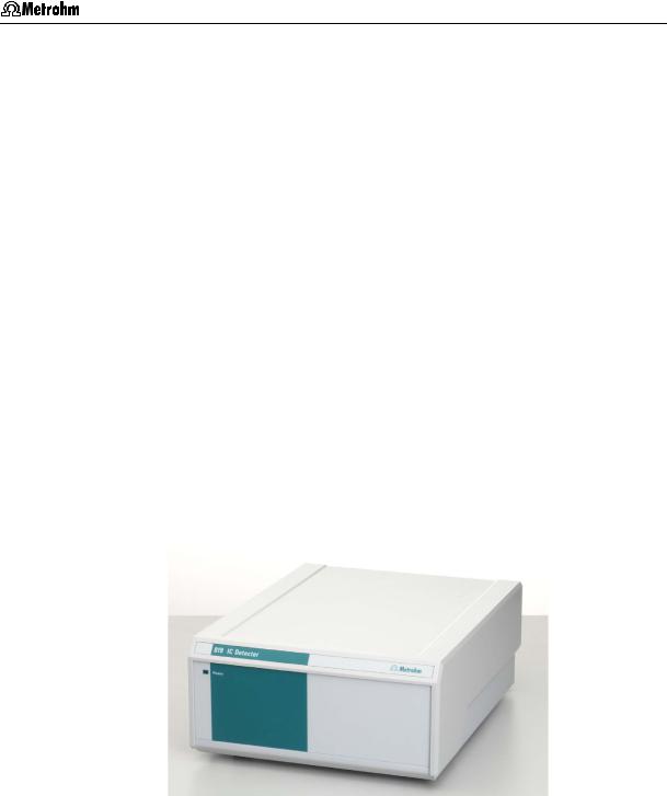
1.1.1819 IC Detector
The 819 IC Detector is a conductivity detector especially designed for ion chromatography with an extensive operating range and high sensitivity for the recording of chromatograms with and without chemical suppression. The associated thermostattable detector block is normally installed in the 819 IC Separation Center, but can also be used as a separate detector. The two following versions are available:
•2.819.0010 IC Detector with metal detector block
•2.819.0110 IC Detector with metal-free detector block
The 819 IC Detector can be fully remotely controlled via the Metrohm «IC Net» software. All functions can be quickly and easily accessed by the software and can be clearly shown on the screen. Apart from setting the measuring parameters, it is possible to draw up any time programs required. These can be used to control a large number of instrument functions and freely programmable events.
The 819 IC Detector is connected via the 830 IC Interface or directly to a PC. The control of the instrument and the recording and evaluation of the chromatograms take place under «IC Net». It is also possible to control external devices or start functions in the IC system from these devices via a “Remote” interface using programmable signals.
819 IC Detector / 820 IC Separation Center |
1 |
1 Introduction
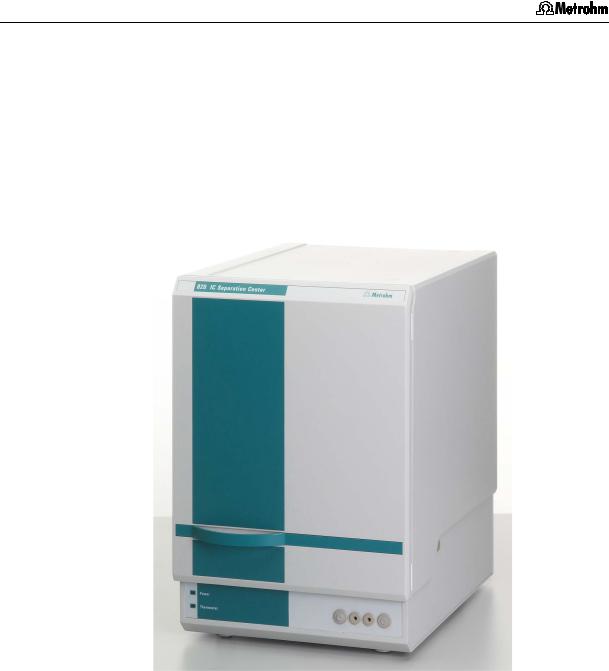
1.1.2820 IC Separation Center
The 820 IC Separation Center is a thermally and electronically insulated wet-chemistry component that accommodates injectors, columns, column heating, detector blocks, suppressor module, pulsation dampeners and various optional sample preparation modules. The 820 IC Separation Center is also remotely controlled via the Metrohm «IC Net» software; it can either be connected to the 819 IC Detector and controlled through it, or connected directly to the 830 IC Interface and controlled directly from «IC Net».
The following versions are available:
• |
2.820.0210 IC Separation Center with 1 injector for a one-channel |
|
system with column heating, metal-free |
• |
2.820.0220 IC Separation Center with 2 injectors for a |
|
two-channel system with column heating, metal-free |
• |
2.820.0230 IC Separation Center with 1 injector and 1 Metrohm |
|
Suppressor Module MSM for a one-channel system |
|
with column heating, metal-free |
• |
2.820.0310 IC Separation Center with 1 injector for a one-channel |
|
system, metal-free |
• |
2.820.0320 IC Separation Center with 2 injectors for a |
|
two-channel system, metal-free |
• |
2.820.0330 IC Separation Center with 1 injector and 1 Metrohm |
|
Suppressor Module MSM for a one-channel system; |
|
metal-free |
2 |
819 IC Detector / 820 IC Separation Center |
1.1 Instrument description
1.1.3Schematic arrangement of the IC systems
The 819 IC Detector and 820 IC Separation Center are the main components of a modular ion chromatography system that can be expanded to meet the wishes of the individual user (see Fig. 1). The minimum configuration of the one-channel system also includes a 818 IC Pump, a separating column, a 830 IC Interface and an PC. The twochannel system requires at least a second 819 IC Detector and a second 818 IC Pump. Both systems can be extended virtually without any limits by further modular Metrohm IC devices such as sample changers for automation, sample preparation devices, components for postcolumn derivation and other detectors. Further, practically all HPLC peripherals and parts available on the market such as precolumns, additional separating columns, additional detectors and other injection systems can be seamlessly integrated in the system.
However, the individual IC units can also be freely combined with common HPLC instruments. This offers the possibility of expanding your system to a stand-alone ion chromatograph.
One-channel system |
Two-channel system |
PR
PC
830
819  819
819
|
|
|
|
|
|
|
|
|
|
|
|
|
|
|
|
|
|
Suppressor |
|
|
|
|
|
Suppressor |
|
W |
|
|
|
D |
|
|
D |
|
|
W |
|
|
|
||||
|
|
|
|
|
|
|
|
|
|
|
|
|
|
|
|||||||
|
|
|
|
|
|
|
|
|
|
|
|
|
|
|
|
|
|
|
|
|
|
|
|
|
|
|
|
|
|
M |
|
|
|
M |
|
|
|
|
Sample |
|
|
||
|
|
Sample |
|
|
|
|
|
|
820 |
|
|
|
|
|
|
|
|
||||
|
|
|
|
|
|
|
C |
C |
|
|
|
|
|
changer |
|
|
|||||
|
|
changer |
|
|
|
|
|
|
|
|
|
|
|
|
|
|
|
|
|
||
|
|
|
|
S |
|
|
|
I |
I |
|
S |
|
|
|
|
|
|||||
|
|
|
|
|
|
|
|
|
Sample |
|
|
||||||||||
|
|
|
|
W |
|
|
|
|
W |
|
|
||||||||||
|
|
|
|
|
|
|
|
|
|
||||||||||||
|
|
Sample |
|
|
|
|
|
|
|
|
|
|
|
|
preparation |
|
|
||||
|
|
preparation |
|
|
|
|
|
|
|
|
|
|
|
|
|
|
|
|
|
|
|
|
|
|
|
|
|
|
|
|
|
|
|
|
|
|
|
|
|
|
|
|
|
|
|
|
|
|
|
|
|
|
|
|
|
|
|
|
|
|
|
|
|
|
|
|
|
|
|
|
|
|
|
|
|
|
|
|
|
|
|
|
|
|
|
|
|
|
|
|
|
|
|
|
|
818 |
|
|
|
|
|
818 |
|
|
|
||||
|
|
|
|
|
|
|
|
|
|
|
|
|
|
|
|
|
|
|
|
|
|
|
|
|
|
|
|
|
|
E |
|
|
|
|
E |
|
|
|
|
|
|||
Fig. 1: |
Block diagram of the ion chromatography systems |
||||||||||||||||||||
C |
Separating Column |
|
M |
Suppressor module |
818 |
IC Pump |
|||||||||||||||
D |
Detector |
|
PC |
PC |
|
|
|
|
|
|
|
|
819 |
IC Detector |
|||||||
E |
Eluent |
|
PR |
Printer |
|
|
|
|
|
820 |
IC Separation Center |
||||||||||
I |
Injector |
|
S |
Probe |
|
|
|
|
|
|
|
||||||||||
IF |
Interface |
|
W |
Waste |
|
|
|
|
|
|
|
||||||||||
819 IC Detector / 820 IC Separation Center |
3 |
1 Introduction
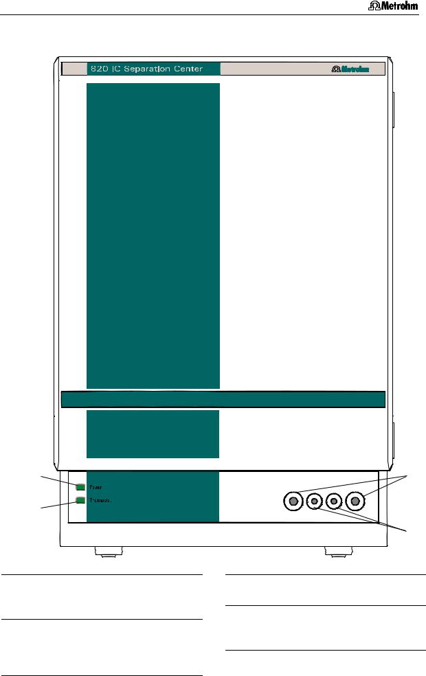
1.2Parts and controls
In this Section you will find the numbers and designations of the parts and controls of the 819 IC Detector and 820 IC Separation Center. The numbering applies throughout the instructions for use, i.e. bold numbers in the text (e.g. 3) refer to the parts and controls illustrated here.
1.2.1819 IC Detector
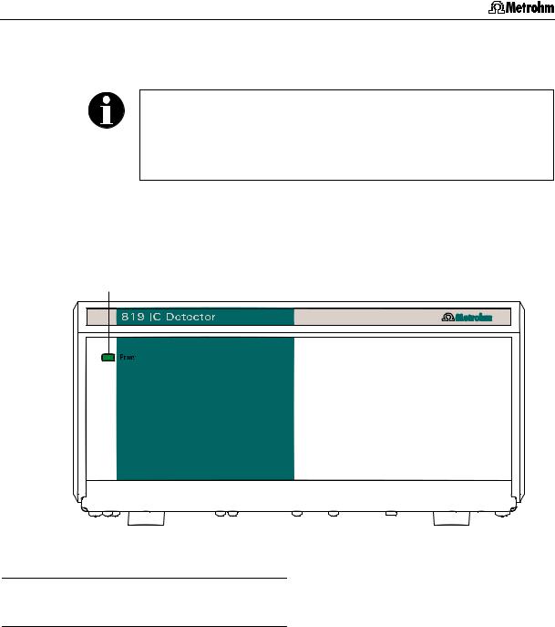
1
Fig. 2: Front of the 819 IC Detector
1Mains pilot lamp
Lights up when instrument is switched on
4 |
819 IC Detector / 820 IC Separation Center |
1.2 Parts and controls
2 |
3 |
4 |
5 |
6 |
7 |
8 |
9 |
10 |
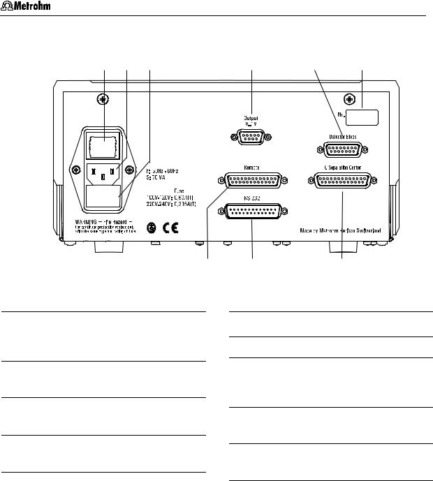
Fig. 3: Rear of the 819 IC Detector
2Mains switch
For switching instrument on/off:
I = ON 0 = OFF
3Mains connection plug
Mains connection see Section 2.4.1
4Fuse holder
Changing the fuses, see Section 2.4.1
5Analog output
0...1 V
6Connection for detector block
7Model plate with serial number
8Remote interface
remote I/O lines for connection of external devices
9RS 232 interface for connection of IC Interface 830 or PC
10Connection for 820 IC Separation Center
819 IC Detector / 820 IC Separation Center |
5 |
1 Introduction
1.2.2820 IC Separation Center
|
1 |
|
|
13 |
|
12 |
|
|
|
|
|
|
|
14 |
|
Fig. 4: |
Front of the 820 IC Separation Center |
||
11 |
Mains pilot lamp |
13 |
Connection for syringe 6.2816.020 |
|
|
Lights up when instrument is switched |
|
|
|
|
on |
|
14 |
Feedthrough |
|
|
|
||
12 |
Thermostat lamp |
|
for sample, eluent, suppressor re- |
|
|
Lights up when column heating is |
|
agent,… |
|
connected, see Section 2.2.2 and Section 2.4.3
6 |
819 IC Detector / 820 IC Separation Center |

1.2 Parts and controls
15 |
16 |
17 18 19 |
20 |
15 |
|
|
|
|
|
21
22 |
23 |
24
15 |
15 |
|
29 |
25 


 30
30
15 |
15 |
26 |
31 |
27 |
|
14 |
14 |
28 |
|
15 |
32 |
18 |
33 |
18 |
34 |
15 |
Fig. 5: Rear of the 820 IC Separation Center
819 IC Detector / 820 IC Separation Center |
7 |

1 Introduction
14Feedthrough
for sample, eluent, suppressor reagent,…
15Knurled screw
for fastening rear panel 21, resp. 28.
16Opening for detector cable B opening for connecting cable: detector block B – 819
17Opening for outlet capillary B discharge of the eluent of column B to waste
18Rear panel opening
(closed with plastic stopper) for additional supply and discharge lines to and from the inner compartment
19Opening for outlet capillary A discharge of the eluent of column A to waste
20Opening for detector cable A and for connecting cable to the column heating
opening for connecting cable: detector block B – 819
column heating – 820 (6.2108.120)
21Detachable rear panel
access to top part of the inner compartment
22RS 232 interface for column heating
to connect to 830 IC Interface or PC with cable 6.2134.040
23Connection for column heating with cable 6.2108.120
24Connection for external power supply of column heating
with power supply unit 6.2152010
25Connection for external power supply of the Separation Center connection of power supply unit 6.2152.000
(5 V, 0.5 A / 24 V, 2 A) in operation without 819 IC Detector
26Terminal block for valve B
Ground, Fill, Inject:
inputs for control of the valve RUN Pos. / COM Fill:
output signal on switching of the valve to position "FILL"
RUN Integr. / COM Start:
output signal on switching of the valve to position "INJECT"
27Connection for 819 IC Detector
28Detachable rear panel
access to bottom part of the inner compartment
29Model plate with serial number
30Connection for 819 IC Detector A
31Terminal block for Valve A
Ground, Fill, Inject:
inputs for control of the valve RUN Pos. / COM Fill:
output signal on switching of the valve to position "FILL"
RUN Integr. / COM Start:
Output signal on switching of the valve to position "INJECT"
32Opening for inlet capillary B supply of the eluent for column B
33Connection for drain tube
for discharge of spilled liquid from the inner compartment
34Opening for inlet capillary A supply of the eluent for column A
8 |
819 IC Detector / 820 IC Separation Center |
1.2 Parts and controls
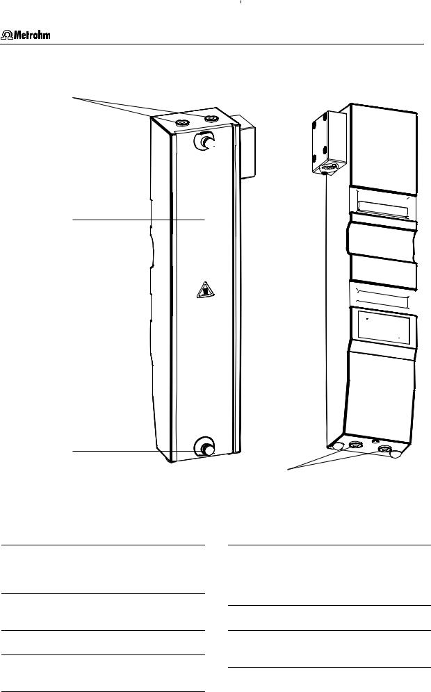
Column heating
35
36 
38 


39 
37
39 
40

|
36 |
|
|
|
|
|
|
|
41 |
|
|
Front |
|
Rear |
|
Fig. 6: |
Column heating closed |
|
|
35 |
Feedthrough |
|
39 |
Magnetic holder |
|
for the capillary from the separating |
|
for fastening the column heater in the |
|
|
column to detector |
|
inner compartment of the Separation |
|
|
|
|
|
Center |
36 |
Knurled screw |
|
|
|
|
for fastening the heater cover 37 |
40 |
Model plate with serial number |
|
37 |
Cover of column heating |
41 |
Feedthrough |
|
|
|
|
|
for column connection capillary 50 |
38Connection for Separation Center with cable 6.2108.120
819 IC Detector / 820 IC Separation Center |
9 |
1 Introduction
1.3Information on the Instructions for Use
Please read through these Instructions for Use carefully before you put the 819 IC Detector and 820 IC Separation Center into operation. The Instructions for Use contain information and warnings which must be heeded the user to assure safe operation of the instruments.
1.3.1Organization
These 8.819.1013 Instructions for Use for the 819 IC Detector and 820 IC Separation Center provide a comprehensive overview of the installation, startup procedure, operation, fault rectification and technical specifications of these instruments. The Instructions for Use are organized as follows:
Section 1 |
Introduction |
|
General description of instruments, parts and controls |
|
and safety notes |
Section 2 |
Installation |
|
Installation of 819 IC Detector / 820 IC Separation |
|
Center, electrical connections, tubing connections, |
|
mains connection |
Section 3 |
Operation |
|
Operation via «IC Net» |
Section 4 Notes - Maintenance - Faults |
|
|
Practical notes, maintenance, fault rectification |
Section 5 |
Interfaces |
|
Description of the interfaces |
Section 6 |
Appendix |
|
Technical data, standard equipment, options, valida- |
|
tion, warranty, declaration of conformity, index |
To find the information you require about the instrument please use either the Table of contents or the Index at the back.
As an addition to the Instructions for Use the Metrohm Monographs listed in Section 6.3.4 can be requested on the Internet under http://www.metrohm.com in the literature section, or free of charge from your local Metrohm agency. Detailed information about separating columns available from Metrohm can be found in the Metrohm IC Column Catalog or on the Internet under http://www.metrohm.com in the ion chromatography range of products. Information about special IC applications is given in the relevant "Application Bulletins" or "Application Notes"; these can be found on the Internet under http://www.metrohm.com in the applications section or can be requested free of charge from your local Metrohm agency.
10 |
819 IC Detector / 820 IC Separation Center |
1.3 Information on the Instructions for Use
1.3.2Notation and pictograms
The following notations and pictograms (symbols) are used in these Instructions for Use:
Range |
Menu item, parameter or entry |
||||
|
|
|
|
|
value |
|
|
|
|
|
in «IC Net» program |
|
|
|
|
|
|
SYSTEM STATE |
Program window |
||||
|
|
|
|
|
in «IC Net» program |
|
|
|
|
|
|
<OK> |
Button |
||||
|
|
|
|
|
in «IC Net» program |
|
|
|
|
|
|
7 |
|
|
Part or control of 819 / 820 |
||
|
|
|
|
|
|
3 |
|
|
Part or control of 818 |
||
|
|
|
|
|
|
21 |
Part or control of 833 |
||||
|
|
|
|
|
|
|
|
|
|
|
Danger/Warning |
|
|
|
|
|
This symbol indicates a possible |
|
|
|
|
|
risk of death or injury to the user |
|
|
|
|
|
and possible damage to the |
|
|
|
|
|
instrument or its components by |
|
|
|
|
|
electricity. |
|
|
|
|
|
|
|
|
|
|
|
Danger/Warning |
|
|
|
|
|
This symbol indicates a possible |
|
|
|
|
|
risk of death or injury to the user |
|
|
|
|
|
and possible damage to the in- |
|
|
|
|
|
strument or its components. |
|
|
|
|
|
|
|
|
|
|
|
Attention |
|
|
|
|
|
This symbol indicates important in- |
|
|
|
|
|
formation that you should read be- |
|
|
|
|
|
fore continuing. |
|
|
|
|
|
|
|
|
|
|
|
Information |
|
|
|
|
|
This symbol indicates additional in- |
|
|
|
|
|
formation and tips which may be of |
|
|
|
|
|
|
|
|
|
|
|
particular use to you. |
|
|
|
|
|
|
819 IC Detector / 820 IC Separation Center |
11 |
1 Introduction
1.4Safety notes
While electrical safety in the handling of the 819 IC Detector and 820 IC Separation Center is assured in the context of the specifications EN/IEC 61010-1 / UL 3101-1 (protection class I), the following points should be noted:
• Mains connection
Setting of the mains voltage, checking the mains fuse and the mains connection must be effected in accordance with the instructions in Section 2.4.
•Opening the 819 IC Detector
Inside the instrument there are no parts which must be set or adjusted by the user.
If the 819 IC Detector is connected to the mains then the instrument must not be opened, nor should any components be removed from it as otherwise you run the risk of coming into contact with currentcarrying components. For this reason you should always separate the instrument from sources of electricity before opening it and also ensure that the mains plug is removed from mains connector 3!
•Opening the 820 IC Separation Center
The instrument contains no components that can be set or adjusted by the user.
Disconnect all connecting cables on the rear of the 820 IC Separation Center before you remove the middle housing panel with connectors.
• Protection against static charges
Electronic components are sensitive to static charging and can be destroyed by discharges. Before you touch any of the components inside the 819 IC Detector or 820 IC Separation Center, you should earth yourself and any tools you are using by touching an earthed object (e.g. housing of the instrument or a radiator) to eliminate any static charges which exist.
1.4.1General precautionary rules
•Handling of solvents
Check all lines of the IC system periodically for possible leaks. Follow the relevant instructions regarding the handling of flammable and/or toxic solvents and their disposal.
12 |
819 IC Detector / 820 IC Separation Center |
2.1 Setting up the instrument
2 Installation
2.1Setting up the instrument
2.1.1Packaging
819 IC Detector and 820 IC Separation Center are supplied together with the separately packed accessories in special packagings containing shock-absorbing foam linings designed to provide excellent protection. The actual instrument is packed in an evacuated polyethylene bag to prevent the ingress of dust. Please store all these special packagings as only they assure transport of the instruments free from damage.
2.1.2Check
After receipt, immediately check whether the shipment is complete and has arrived without damage (compare with delivery note and list of accessories in Section 6.2). In the case of transport damage, see instructions in Section 6.5.1 "Warranty".
2.1.3Location
Position the instrument the laboratory at a location convenient for operation, free from vibrations and protected against a corrosive atmosphere and contamination by chemicals.
To avoid disturbing temperature influences on the insulated column compartment, the pump and eluent reservoir must be protected against direct sunlight.
2.1.4Arrangement of the instruments
Modular IC instruments can be stacked on top of each other in any sequence.
In a modular system any instruments containing liquid-transporting assemblies should always be located as low down in the stack as possible, so that any leaks which may occur in tubing or connections will cause no damage to the other instruments by escaping liquids such as acids.
819 IC Detector / 820 IC Separation Center |
13 |
2 Installation
In one-channel operation, the 818 IC Pump, 820 IC Separation Center and 819 IC Detector are best stacked on top of one another in this order.
In two-channel operation (2.820.0X20 IC Separation Center), the optimum arrangement (1, 2 or 3 towers) depends on the laboratory space available. However, the 818 IC Pumps should be set up at the very bottom and the 819 IC Detectors at the very top.
To ensure that the arrangement of pumps and detectors for the two channels A and B is clearly apparent in two-channel operation, it is advantageous to mark the instruments. The 6.2248.000 Magnetic plate is enclosed with the 819 IC Detector for this purpose. It can be cut to the desired size, labeled (e.g. with "A" or "B") and affixed to the appropriate instrument.
14 |
819 IC Detector / 820 IC Separation Center |
2.2 Installation of accessories
2.2Installation of accessories
2.2.1Insert detector block
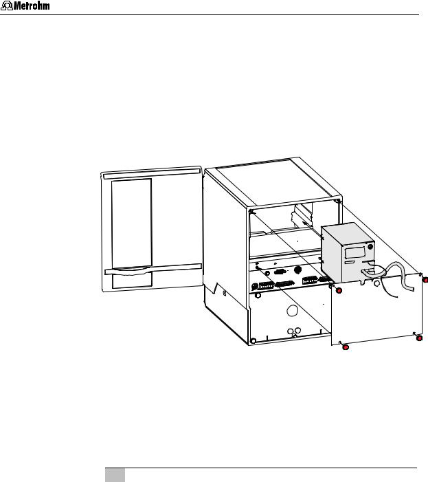
In order to operate an 820 IC Separation Center with an 819 IC Detector the detector block contained in the standard equipment of the detector (1.732.0110 Detector block metal-free or 1.732.0100 Metal) must be inserted in the upper part of the Separation Center.
Fig. 7: Insert detector block in the Separation Center
2.820.0X10/2.820.0X30 IC Separation Center
The instrument versions 2.820.0X10 and 2.820.0X30 of the IC Separation Center are operated with one 819 IC Detector. It is best to proceed as follows when connecting the two instruments and the detector block:
1Install detector block
•Unscrew the four knurled screws 15 from the top rear panel 21 of the 820 IC Separation Center and remove rear panel (see Fig. 5).
•Position detector block from the back in the space provided in the 820 IC Separation Center on the right and push fully to the front (see Fig. 7, resp. Fig. 21 and Fig. 23).
•Insert the cable permanently attached to the detector block in opening 20 and the outlet capillary in opening 19 "Waste A" of the rear panel 21.
•Replace rear panel 21 and screw to the 820 IC Separation Center using the four knurled screws 15.
819 IC Detector / 820 IC Separation Center |
15 |
2 Installation
819
Cable from detector block
820
Fig. 8: Connection Detector 819 – 2.820.0X10/2.820.0X30
2Connect detector block
•Plug the gray connecting cable permanently attached to the detector block into connection 6 „Detector Block“ of the 819 IC Detector and fasten to the instrument by tightening the screws in the cable connector (see Fig. 8).
3Connect waste container
•Lead the outlet capillary of the detector block to a sufficiently large waste container and fix in place.
2.820.0X20 IC Separation Center
The two-channel versions 2.820.0X20 of the IC Separation Center can be operated with two 819 IC Detectors. It is best to proceed as follows when connecting the instruments and the two detector blocks:
1Install detector blocks
•Unscrew the four knurled screws 15 from the top rear panel 21 of the 820 IC Separation Center and remove rear panel (see Fig. 5).
•Position first detector block from the back in the space provided in the 820 IC Separation Center on the right and push fully to the front (see Fig. 7, resp. Fig. 22 and Fig. 25).
•Position second detector block from the back in the space provided in the 820 IC Separation Center on the left and push fully to the front (see Fig. 7, resp. Fig. 22 and Fig. 25).
•Insert the cable permanently attached to the detector block A in opening 20 and the outlet capillary in opening 19 "Waste A" of the rear panel 21.
•Insert the cable permanently attached to the detector block B in opening 16 and the outlet capillary in opening 17 "Waste B" of the rear panel 21.
16 |
819 IC Detector / 820 IC Separation Center |
2.2 Installation of accessories
•Replace rear panel 21 and screw to the 820 IC Separation Center using the four knurled screws 15.
2Connect detector blocks
•Plug the gray connecting cable permanently attached to the detector block A into connection 6 „Detector Block“ of the first 819 IC Detector and fasten to the instrument by tightening the screws in the cable connector (see Fig. 9).
•Plug the gray connecting cable permanently attached to the detector block B into connection 6 „Detector Block“ of the second 819 IC Detector and fasten to the instrument by tightening the screws in the cable connector (see Fig. 9).
3Connect waste container
•Lead the outlet capillary of both detector blocks to a sufficiently large waste container and fix in place.
|
819 |
|
|
|
|
|
|
|
|
819 |
|
Cable from |
|
Cable from |
detector block B |
|
detector block A |
820
Fig. 9: Connection 2 x 819 Detector – 2.820.0X20
819 IC Detector / 820 IC Separation Center |
17 |

2 Installation
2.2.2Connection of column heating
The instrument versions 2.820.02X0 of the IC Separation Center contain a column heating for thermostatting the separating column as an option. If you wish to use this column heating then it should be installed as follows:
Fig. 10: Install column heating in Separation Center
1Laying the connection cable
•Screw off the 4 knurled screws 15 from upper rear panel 21 of the 820 IC Separation Center and remove the rear panel (see Fig. 5).
•Lead 6.2108.120 Cable through opening 20.
•Replace rear panel 21 and screw it onto 820 IC Separation Center using the 4 knurled screws 15.
2Insert column heating
•Carefully place the column heating inside the Separation Center. If the column has already been inserted in the heating then be careful with the capillaries at feedthroughs 35 and 41
(see Section 2.9.2).
•Use magnetic holder 39 and the corresponding counterpieces to attach the column heating to the left-hand inside wall of the Separation Center.
3Connect column heating
•Insert 6.2108.120 Cable at connection 38 of the column heating (see Fig. 6) and at connection 23 on the rear panel of the Separation Center (see Fig. 5).
18 |
819 IC Detector / 820 IC Separation Center |
2.2 Installation of accessories
820
6.2108.120
Fig. 11: Connection 820 – column heating
2.2.3Connection of syringe and aspirating tubing
For manual filling of the sample loops mounted on the injection valves, the 6.2816.020 Syringe and the PTFE aspirating tubing already screwed to the valve are needed. These accessories are mounted or adjusted as follows:
1Connect syringe
•Push 6.2816.020 Syringe (without needle) as far as it will go into connection socket 13 (left for valve A, right for valve B) (see Fig. 4).
2Lead aspirating tubing to the outside
•Lead the PTFE aspirating tubing 63 (see Fig. 21, Fig. 22 resp. Fig. 23) through one of the feedthroughs 14 at the front or side of the separation center (see Fig. 4 and Fig. 5) to the outside.
2.2.4Connection of the drain tube
The 820 IC Separation Center has a connection at the rear to which a drain tube for discharged liquids can be attached. Proceed as follows:
1Connect drain tube
•Mount 6.1816.00 Silicone tubing on connection nipple 33 (see Fig. 5).
2Lead drain tube to collecting vessel
•Lead the other end of the drain tube to a suitable collecting vessel and fix in place.
2.2.5Connection of the 6.5324.000 Bottle rack (option)
The optional available 6.5324.000 Bottle rack for supply vessels can be placed on top of the IC system tower. The accessories include the supply vessels for eluent (2 L), regeneration solution (1 L) and rinsing solution (1 L). For the connection of the supply capillaries leading to the 818 IC Pump and the suppressor module, see the instructions given on the enclosed leaflet.
819 IC Detector / 820 IC Separation Center |
19 |
2 Installation
2.3Electrical connection
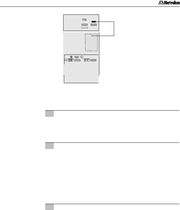
2.3.1Connection to 830 IC Interface
The instruments are controlled via the Metrohm «IC Net» software. They are normally connected to a PC via an 830 IC Interface.
The 820 IC Separation Center can be operated in two different ways. It can operated via the 819 IC Detector, or included as an independent instrument in the «IC Net» via the 830 IC Interface. Both the cable connections and the installation under «IC Net» depend on the type of control.
Control of the Separation Center via 819
Normally the Separation Center is controlled with «IC Net» via the time program of the detector. When a system is being set up either 820.02X0 to IC Detector or 820.03X0 to IC Detector must be selected for the Separation Center in «IC Net».
In a 2-channel system each channel of the Separation Center is controlled via the time program of the assigned detector.
|
|
|
|
|
|
|
|
|
|
|
|
|
|
PC |
|||
|
|
|
|
|
|
|
|
|
|
|
|
6.2134.100 |
|||||
|
|
|
|
|
|
|
|
|
6.2115.070 |
|
6.2134.130 |
||||||
|
|
|
|
|
|
|
|
|
|
|
|
||||||
|
|
|
|
|
PC |
|
|
|
|
|
|
|
|
|
|||
|
|
|
6.2134.100 |
6.2134.130 |
830 |
|
|
|
|
|
|
6.2115.070 |
|||||
|
|
|
|
|
|
|
|
|
|
||||||||
|
|
|
|
|
|
|
|
|
|
|
|
|
|
|
|
||
6.2115.070 |
|
|
|
|
|
|
|
|
|
|
|
|
|
|
|
|
6.2134.090 |
|
|
|
|
|
|
|
|
|
|
|
|
|
|
|
|
||
|
|
|
|
|
|
|
|
|
|
|
|
|
|
|
|
|
|
|
|
|
|
|
|
|
|
|
|
|
|
|
|
|
|
|
|
6.2134.130 |
830 |
|
|
|
|
|
|
|
|
819 B |
|
|
|
|
|
6.2125.090 |
|
|
|
|
|
|
|
|
|
|
|
|
|
|
|||||
|
|
|
|
|
|
|
|
|
|
|
|
|
|
|
|
|
|
|
|
|
|
|
|
|
|
|
|
|
|
|
|
|
|
|
|
|
|
|
|
|
|
|
|
|
|
|
|
|
|
|
|
|
|
|
819 |
|
|
|
|
|
|
|
|
819 A |
|
|
|
|
|
|
|
|
|
|
|
|
|
|
|
|
6.2125.090 |
|
|
|
|
|
|
|
6.2125.090 |
6.2134.090 |
|
|
|
|
|
|
|
|
6.2134.090 |
|
|
|
|
|
|
|
|
820 |
|
|
|
|
|
|
|
820 |
|
|
|
|
|
|
|
||
|
|
|
6.2134.040 |
|
|
|
|
|
6.2134.040 |
|
|
||||||
|
|
|
|
|
|
|
|
|
|
|
|
|
|
|
|
|
|
|
|
|
|
|
|
|
|
|
|
|
|
|
|
|
|
|
|
One-channel system |
Two-channel system |
Fig. 12: Connection of 820 via 819 to 830
20 |
819 IC Detector / 820 IC Separation Center |
2.3 Electrical connection
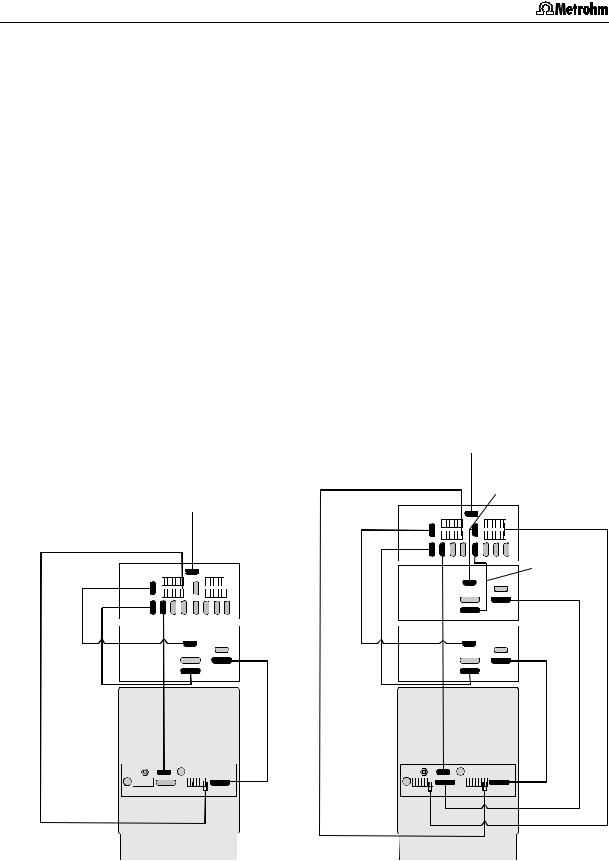
1Connect 819 to 820
•Use 6.2125.090 Cable to connect Connection 10 “IC Separation Center” of the 819 IC Detector to Connection 30 “IC Detector” of the 820 IC Separation Center (see Fig. 12).
For the 2-channel versions 820.0X20 additionally:
•Use a further 6.2125.090 Cable to connect Connection 10 “IC Separation Center” of the second 819 IC Detector to Connection 27 “IC Detector” of the 820 IC Separation Center (see Fig. 12).
2Connect 819 to 830
•Use 6.2134.090 Cable (830 accessory) to connect Connection 9 “RS 232” of the 819 IC Detector to a free RS 232 interface of System 1 of the 830 IC Interface (see Fig. 12).
•Use 6.2134.130 Cable to connect Connection 5 “Output” of the 819 IC Detector to analog connection “Channels 1/2” of
System 1 of the 830 IC Interface (see Fig. 12).
For 2-channel versions 820.0X20 additionally:
•Use a further 6.2134.090 Cable (830 accessory) to connect Connection 9 “RS 232” of the second 819 IC Detector to a free RS 232 interface of System 2 of the 830 IC Interface (see Fig. 12).
•Use 6.2134.130 Cable to connect Connection 5 “Output” of the 819 IC Detector to analog connection “Channels 3/4” of
System 2 of the 830 IC Interface (see Fig. 12).
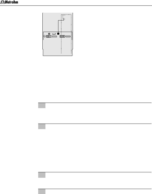
3Connect 820 to 830
This cable connection starts data recording (chromatogram window turns blue) when the valve in the 820 is switched to INJECT via a program command; not necessary if valve is operated manually:
•Use 6.2115.070 Cable to connect the positions Integr. and
Start of terminal block 31 of the 820 IC Separation Center to the event line Start of System 1 of the 830 IC Interface
(see Fig. 12).
For 2-channel versions 820.0X20 additionally:
•Use a further 6.2115.070 cable to connect the positions Integr. and Start of terminal block 26 of the 820 IC Separation Centers to the event line Start of System 2 of the 830 IC Interface (see Fig. 12).
Take care that each of the RUN connections at 830 and 820 and the COM connections at 830 and 820 are connected to each other.
4Connect column heating to 830
For 820.02X0 only:
•Use 6.2134.040 Cable to connect RS 232 interface 22 of the 820 IC Separation Center to a free RS 232 interface of the
830 IC Interface (see Fig. 12).
819 IC Detector / 820 IC Separation Center |
21 |
2 Installation
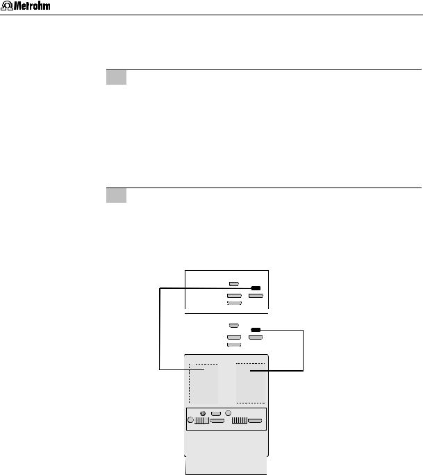
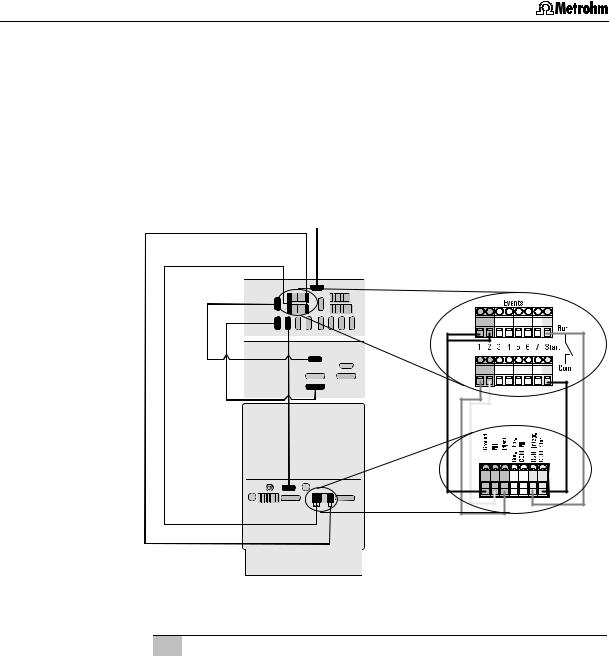
Separate control of the Separation Center
Alternatively you have the possibility of controlling the Separation Center with its own time program from «IC Net». This requires you to select the appropriate 820.0210 to Interface, 820.0220 to Interface, 820.0230 to In-
terface, 820.0310 to Interface, 820.0320 to Interface or 820.0330 to Interface for the Separation Center when setting up the systems in «IC Net».
6.2115.070
PC
6.2134.100
6.2128.100
6.2134.130 830
819
6.2134.090 820
6.2134.040
Fig. 13: Connection of 819 and 820 to 830
1Connect 819 to 830
•Use 6.2134.090 Cable (830 accessory) to connect Connection 9 “RS 232” of the 819 IC Detector to a free RS 232 interface of System 1 of the 830 IC Interface (see Fig. 13).
•Use 6.2134.130 Cable to connect Connection 5 “Output” of the 819 IC Detector to the analog connection “Channels 1/2” of System 1 of the 830 IC Interface (see Fig. 13).
22 |
819 IC Detector / 820 IC Separation Center |
Loading...